Poor print quality with RRF3 - especially 3.2.2.
-
@deckingman sure, sorry, just trying to cover all the bases...
Ian
-
I recently had a part cooling problem that looked very much like the pictures of the poor quality print.
Is it possible there is a intermittent connection to the part cooling fan(s)?
That might explain the unpredictable nature of the print quality.
Frederick
-
@fcwilt said in Poor print quality with RRF3 - especially 3.2.2.:
........................ Is it possible there is a intermittent connection to the part cooling fan(s)?
None that I can see or detect.
-
@deckingman said in Poor print quality with RRF3 - especially 3.2.2.:
Hi Ian,
In my opinion the logical first test is your choice #2"I can map UV to XY such that the two gantries are combined and the firmware doesn't have to synchronise UV moves to XY moves where those UV moves are shorter than the XY moves, Although then I'd have re-enable the AB gantry."
Seems like it would take some work load off the system. I'm sure it can handle it but this would be a good way to confirm it.
And then work from there.
Personally I have withheld making the jump to 3 just from the complexity of it all. I feel it will be a great product after some time and I love the direction Duet is going with CANbus.
I need to build an extra printer so I can devote time to the upgrade. I just can't afford to have any printers down right now with debugging.
Cheers,
Tim -
Cooling fans and reaction times on a big mixing head are slow. Looking closely at the problem pictures the built quality on the larger surfaces looks spot on.
Ian, with your current settings what sort of distance does the machine travel while accelerating? Still running without pressure advance? Any idea how much distance would be added if you include the area that is effected by PA?
Does it appear to go bad before, after, or symetric around the trouble corners?
-
@deckingman said in Poor print quality with RRF3 - especially 3.2.2.:
I can dissable the AB load balancing gantry and remove all references to AB from the config files, macros, and the post processing script. Now that the 6 heavy extruders no longer replicate the hot XY hot end moves, the machine no longer rocks around with high speed moves, so it isn't necessary. But it's a lot of work to change all those files and scripts.
IMHO having that as "optional" would be great, moving all that to a separate file that can be load or not might be a good idea in the long run so why not go with it sooner than later, not that you can print anything

Testing without these 2 axes will show if those 2 additional axes are making a problem. Not many ppl use a lot of axes with duet3d (looking at multi axis CNC machines I still don't see many of them use duet3d hw) so it is maybe not something that's properly tested. I doubt this will be a solution but as you might do it anyhow..
I can map UV to XY such that the two gantries are combined and the firmware doesn't have to synchronise UV moves to XY moves where those UV moves are shorter than the XY moves, Although then I'd have re-enable the AB gantry.
If I remember your writing, you stated that while AB gantry did eliminate the machine shaking it did not affect print quality so I assume you can map UV to XY and not reenable AB gantry. The machine will shake and dance a bit but it will not affect print quality. I believe for the test that is acceptable. This will remove 2 more axes from the story, with [1] that's 4 axes less... Again I doubt it will solve the problem but at this point who knows.
I can look at whatever other sensible suggestion arise from this post.
If firmware creator want to spend some time on this I'll bet they will need a bunch of tests with "exactly the same" everything except for a single simple change + logs for you to find a 2 test scenarios that produce good and bad piece and where theer's only one or two changes between them... It is hard to debug and require both you and firmware creator to spend a lot of time debugging and is going to be frustrating at first I'm sure.
I can try 3.3. beta firmware if there is any likelihood that it will improve anything.
From what I understand 3.3b has a lot more logging and for that alone I believe testing 3.3 is worth it.
I can tear out the gen 3 hardware and revert back to gen 2.
I can say that on a "regular" printer (dual extruder, cartesian, nothing special) on duet2 firmware is only getting better, I have seen no issues so far, def. no worse quality, but I doubt that's comparable to what you are doing.
I can give up completely.
please don't.
few questions
- is this water cooling setup or air cooling setup
- is this your design single input extruder or something commercial?
-
@DocTrucker said in Poor print quality with RRF3 - especially 3.2.2.:
Cooling fans and reaction times on a big mixing head are slow.
As per my previous posts, this is with small, single input hot end - not a large mixing hot end.
Looking closely at the problem pictures the built quality on the larger surfaces looks spot on.
That's true for the second print but not for the first print.
Ian, with your current settings what sort of distance does the machine travel while accelerating?
Well actually, the machine doesn't travel at all - it just sits in the same spot inside a booth in my garage.

On a slightly more serious note, if my maths serves me correctly, then with the acceleration set as it is to a modest 1000 mm/sec^2, it will take 0.08 seconds to accelerate from a starting velocity of zero to the print speed of 80mm/sec for inner perimeters and the distance travelled during that acceleration phase would be around 3.2mm. On the other hand, if jerk is applied than the initial velocity would be 15mm/sec (900mm/min) so the corresponding change in velocity would take 0.065 seconds and the distance would be 2.11 mm. But for the outer perimeters, the speed is 50% of the "normal" print speed so only 40mm/sec. In which case, the times and distances are reduced to 0.04 sec and 0.8mm without jerk and 0.025 sec and 0.3125 mm with jerk applied.
So in summary, the distance that the carriage moves during the acceleration phase of print moves is between 3.2 and 0.03 mm depending on whether it's an inner perimeter and infill, or if it's an outer perimeter and/or if it's the first move of a layer change or if "jerk" is applied.
Not sure how any of that is relevant.........
Still running without pressure advance? Any idea how much distance would be added if you include the area that is effected by PA?
Again, as per me previous post, pressure advance seems to be broken (or at least it was on an earlier print) so these two prints were done without.
Does it appear to go bad before, after, or symetric around the trouble corners?
Seems pretty symmetrical on the first print - corners look good on the second print. But as per previous post, 3 of the 4 corners are bad, the 4th corner is fair. Also, yet again can I refer you back to my earlier post stating that for the first and last n mm of Z travel the corners are fair to reasonable.
-
@arhi said in Poor print quality with RRF3 - especially 3.2.2.:
From what I understand 3.3b has a lot more logging and for that alone I believe testing 3.3 is worth it.
Yes, if the issues are anything to do with CAN messages being delayed or lost then 3.3beta will reveal it in the M122 logs.
-
For info, the hot end for these latest tests is an unmodified, "off the shelf" liquid cooled offering, fitted with a E3D 0.5mm standard brass nozzle, and E3D standard thermistor cartridge. The heater is either 30 or 40 watt - can't remember which off hand. The only concession is that I've made my own aluminium liquid cooling adaptors which have a 3mm ID bore, rather than using standard PTFE Bowden tubing with a 2mm bore. This greatly improves the coolant flow (3mm bore tubes have more than double the cross sectional area of 2mm bore). It's this one
I've printed temperature towers and retraction test parts to determine the best settings to use with this hot end. I've also tuned the PID parameters using the latest algorithm, with and without the part cooling fans.
In a nutshell, I've done all the basic stuff and if there was a problem with this hot end I would expect those problems to be consistent and not variable form one day to the next.
-
Could I also respectfully ask those trying to help, to read the previous posts. Repeatedly answering the same questions is more than a little tiresome.
-
what is the size difference between the 2 parts printed ? i can estimate the size of the chuck holder but have no reference for the second "bad" print .
you mention using post processing script to generate uv moves , can this script alter xy moves somehow (is that a secret script) ?
did you try printing without post processing ?do you use anything variable in the slicer (layer height , extrusion , infill etc) ?
if it was a print without any post process / pressure advance /variable slicing i would say that you have extrusion problem at particular feed rates . your "bad" print has some good corners .
-
Update.
I've printed the exact same part as before, with the exact same settings and with the exact same firmware (3.2.2.).
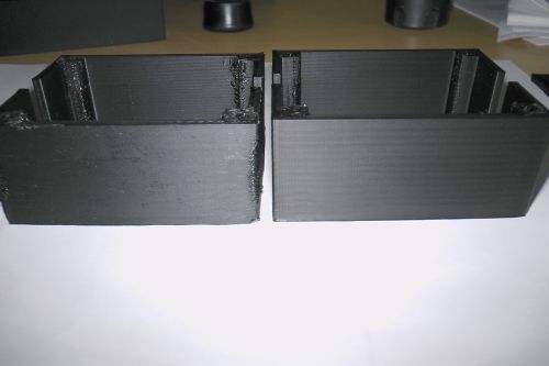
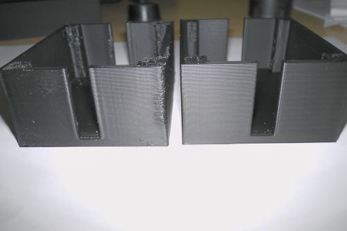
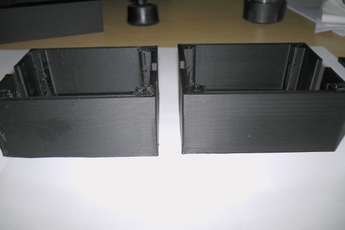
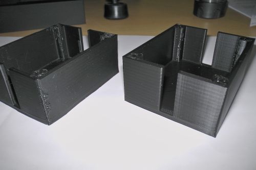
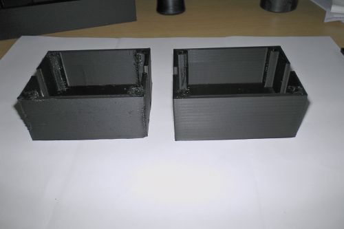
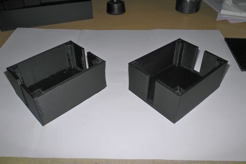
Here are some pics of both parts........
OK, the one on the rights isn't perfect but it's "acceptable". I'd say it needs a tad more retraction but that's entirely consistent with my having disabled pressure advance.
The only difference between these two prints is that the first was printed yesterday and the second was printed today. Go figure..........
I can only assume that firmware is a fan of The Boomtown Rats and doesn't like Mondays.
-
The chuck holder is about 143mm (x) x 60mm (y) by about 50mm (z). The case is is about 72m (x) x 58mm(y) x 31mm (z).
-
@deckingman the pictures are quite small, is that forum software doing somethis or you are putting small pictures?
Once I had a part cooling fan cable that was getting loose during some moves as luck would have it and my problem seemed similar to yours (already mentioned in the thread). This was difficult to figure without sitting down and watching the print as it goes and notice intermittent fan speed changes. However looking closer (as much as possible with small pictures) I don't think that cooling is the issue here because my parts would be more smooth in deformation in the middle, so printing lines were definitely not visible in the middle of shrink area (although this was ABS maybe PLA is different?). Its an easy check so maybe check few wires.
As a data point moving from RRFv2 to RRFv3 was weird with various glitches but I've always attributed random stuff to the fact that I once reverse wired the board (while solving jumpy voltage readings in my board). But I don't want to complain much since I don't contribute any code to RRF and dc should take some vacations.
-
@deckingman said in Poor print quality with RRF3 - especially 3.2.2.:
The only difference between these two prints is that the first was printed yesterday and the second was printed today. Go figure..........
I can only assume that firmware is a fan of The Boomtown Rats and doesn't like Mondays.Thanks for repeating that print.
I think the print on the left shows signs of high or fluctuating temperature, or usual temperature but insufficient cooling. The only ways that I think firmware could cause that are:
- Assuming that the print cooling fan is connected to one of the expansion boards, then I guess it's possible that the fan failed to turn on at the end of the first layer, if that is where you turn it on. If the slicer never changes the fan speed again, that would leave it with the fan off for the whole print.
- If the firmware used the wrong thermistor parameters then the temperature could be too high
- If the firmware somehow set the wrong temperature then it could be too high
Of these, I think the first one is just about plausible, but the other two are extremely improbable.
As others have suggested, it's also possible that a loose wire or stuck fan caused the print cooling fan not to be running through that print. Do you run the print cooling fan at less than full power? If so, do you have a suitable full-power blip configured to ensure that it starts reliably? If your printer is in the garage and it was especially cold when you started the first print, then it's possible that a longer full-speed blip might have been needed to start it.
In theory a poor thermistor connection could also cause the temperature to read lower than it actually is. However, poor thermistor connections usually cause obvious fast temperature reading fluctuations, and often heater faults; so I think we can discount that.
BTW today I have been working with another user with 6HC and 3HC boards, and identified and fixed a CAN communication issue that was occurring with a sample print he provided. I don't think the main print quality issues visible on your first print are caused by the same issue, however it's possible that this issue could be affecting the fine detail of your print. That thread is at https://forum.duet3d.com/topic/21710/3-3b1can-timeout-resets-itself/14. If you try printing using 3.3beta1 then the M122 diagnostics will show whether that issue affects your prints.
-
Just as an FYI, I have had multiple occasions where fan speed changed because of friction on the bearing due to poor quality / cheap fan/ age. You can't see those changes but sometimes you can hear them.
I am not saying that this has anything to do with what you are experiencing, just saying that if cooling can cause these issues then it might be worthwhile changing the fan to see if the inconsistent behaviour changes.In my experience the RPM of the fan can stay the same for long periods and then suddenly drop substantially before resuming normal speed. Sometimes speed goes all over the place.
-
@deckingman said in Poor print quality with RRF3 - especially 3.2.2.:
t
For What its worth - I've experienced similar things related to pressure advance. Similarily, stuff didn't overlap when i was very used to it working. Spooky.
I too have also had the same issues with step pulses, missing steps, etc using expansion boards, etc. I totally believe that you're experienced and have troubleshot stuff (and know what you're doing). Prints are iffy for weird reasons. Settings that work sometimes don't work. Weirdest thing i struggled with was constant jamming. 3.3beta fixed that. no other changes.
That being said - I spent an entire weekend diagnosing an intermittent issue with a CAN toolboard (not RRF, was actually for klipper) that involved trying several expensive new can adapters, network settings, re-crimping connectors, everything but the root cause - the wire had fatigue failed and was occasionally connecting long enough to start a print until eventually losing connection. Sometimes it may be the simple things.
Real suggestion: Are you using an SBC? If so - try going standalone. Spooky things happen with SBCs.
-
I'll repeat that print again today and stand and watch it the whole time. I didn't notice anything unusual on the temperature graph - it was a nice straight line without any temperature excursions.
I'm not convinced that it's part cooling fan related. I often print parts without any cooling at all and I've never seen that sort of behaviour on corners. But there are two 30mm blower fans, one either side and they are audible, so it'll be easy enough to tell if they misbehave.
I've noticed something else strange too, but I'll start a new thread about that. -
@akstrfn The pictures have been resized to 500 pixels wide from their original 4000 odd. That's just because there is a forum limit on the file size which can be directly uploaded. I can upload the originals to my Google drive and provide a link if necessary. But the comparison between good and bad prints is like night and day, even at 500 pixels wide.
-
@deckingman its not about two obvious differences which are almost useless for any conclusion because one is a disaster and the other one is not. I've uploaded much bigger picture to this forum before so no need to make them so small (besides pixels there is also compression).
When debugging multithreading problems, which can be classified as random by the outside observer, you need to heavily focus on the bad case if you can catch it and you did catch it. So the reason why I commented the close ups is because printing lines would be more visible which could help us understand if duet gives wrong commands or you have a possible cooling problem. I wrote an explanation about it in my post but you are quite upset and skipped it apparently.
Next considering that on straight lines you seems to have good results you can eliminate whole host of issues e.g. mechanical ones but it can also point out that duet has issue with multiple small movements. If I'd have to debug this problem in RRF I'd start with sync between extruder and the other motors when cornering. What you can do without coding is to make an object with a lot of corners, few round areas and maybe throw in few long walls in it. Another thing that you can do when debugging wires that act weirdly it to print objects all around the build plate e.g. 9 objects or 12 equally spaced with max distances between them so that you cover all possible wire movements.
But I will mention again that from your pictures (small and compressed ones) it does not seem like cooling simply because your corner areas look like you have uneven layer lines on the corners i.e. one layer looks like its over another layer and also it seems that the problem hits at different heights at random. But I will mention again that this might be just my lack of experience with PLA which maybe degenerates just like whats on your pictures. ABS and PETG 99% does not look like that when overheated (it can actually look very nice).
I can understand the frustration when people tell you that there is no problem "because it works on my machine" which is very common for forums, but most people here are not saying so and believe that there is a real problem with RRF so please relax a bit.
