IDEX CoreXY, With Only 2 Motors.
-
I think its a good thought, but I'm not sure I understand the purpose of locking the carriages to save a stepper. You would just be adding more moving weight, as the second motor on a dual markforged is parked on the frame.
You are welcome to check out my project, it might give you some ideas at the very least. https://github.com/3dprintingworld/MULDEX
I think the purpose of this would mostly be an effective way to add independent dual extrusion to an existing CoreXY printer, without the need to redesign a lot of key components.
Nice work on Muldex btw, it was the only DIY build IDEX printer I could find, and I do like it, but I thought it would be interesting to see what other options could potentially be possible.
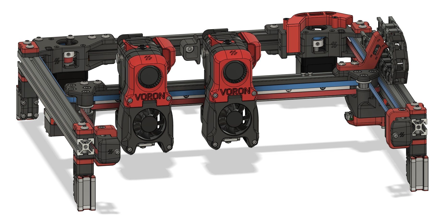
Quite partial to the fixed bed, gantry z movement, and well designed form factor with no wasted space of the Voron, When I started looking over the design, I noticed there was no easy method to add additional belts and motors, not without redesigning all of the major components. That’s when I had the idea for a servo lock. It’s not flash, it’s relatively simple, but I think the concept of having only two motors responsible for the xy movement of two separate carriages, and how the firmware must interact to make it so is very intriguing, and perhaps this will spark other ideas.
Still unsure how racking would show? Lost steps and screeching carriers?
I think racking will boil down to how tightly build a gantry design is. Its hard to say without testing, and I dont know how racking would present itself in a print, possibly out of square corners, or misaligned layers. I think the best gauge would just be to see if you can feel for any play when trying to rock the gantry.
-
@RichardDuke Got it, I love the thought. I would love to see what you come up with.
BTW... Have you thought about swamping carriages, maybe it would fit your application better? You park a carriage at each end of X axis gantry. Then your tool can pick up either carriage. This might be easier to incorporate into an existing corexy design.
-
It has crossed my mind, but it would require a coupler that was fairly acurate. I think I would probably end up with a result much like the toolchanger and park the tools off the carriage instead.
It just seemed so easy to throw on another carriage without much modification!

Richard
-
@RichardDuke Seems simple enough, I guess you never know for sure unless you try!
-
@RichardDuke
In case of the Voron it seems, you'd fit the whole extruder with only two screws to the carrier? You would loose the screws, that otherwise hold the belt-clamp.
Is there a way to use countersunk screws, like I did?I'm trying to find a way to switch the locks without servos.
Just by moving against the far end of the printer, both carriers would simultanously push a springloaded switch, that toggles their lock/unlock hooks. Not sure yet, how to do this but it's there -
@o_lampe I have redesigned it so there are two cap screws and 2 c/sunk screws. The c/sunk ones are just hiding behind the belts. There is also an additional linear rail on the underside of the 2020 extrusion so in total, 8 bolts per carriage, a bit extreme. Edited* the belt clamps are secured with seperate bolts that run parallel to the gantry. They are not shown in the image, but it all still fits.
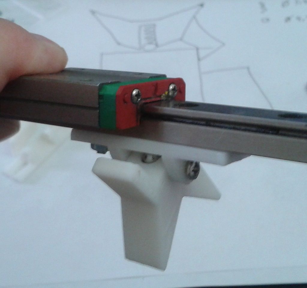
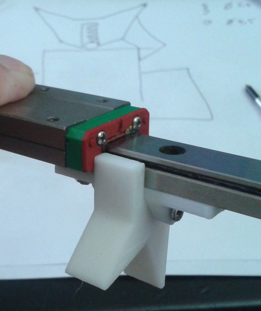
I too have been thinking about alternative locking mechanisms. I think the most ideal solution will be some kind of bushing in the carriage, that a machined shaft is inserted into to pin it in place. Its going to be crucial that the parked carriage has no movement otherwise this will translate into the print quality.
I have been scouring AliExpress for various bits of hardware that could be potential candidates but struggling to find something suitable. I did come across some small form 12v door latch solenoids that I liked the idea of, but I would be positive the solenoid pin will have some amount of play.
I figure if you can have 2 servos, latch/unlatch the carriages, you should be able to rig both latches to a single central servo with some actuator rods ect. But your idea of a full mechanical solution is a neat idea, I will have to give it some more thought, I’m not sure if it’s possible though as there will likely be a moment where both carriages must simultaneously move together which would likely loose the Y position, although this could be rectified with a home between tool change.
-
@o_lampe said in IDEX CoreXY, With Only 2 Motors.:
I'm trying to find a way to switch the locks without servos.
Just by moving against the far end of the printer, both carriers would simultanously push a springloaded switch, that toggles their lock/unlock hooks. Not sure yet, how to do this but it's thereYou know what, I have done some finger paintings on my phone in bed, which I am not quite prepared to publish haha, but I think this may actually be possible. I will sketch something better in the morning
-
@RichardDuke said in IDEX CoreXY, With Only 2 Motors.:
@o_lampe said in IDEX CoreXY, With Only 2 Motors.:
I'm trying to find a way to switch the locks without servos.
Just by moving against the far end of the printer, both carriers would simultanously push a springloaded switch, that toggles their lock/unlock hooks. Not sure yet, how to do this but it's thereYou know what, I have done some finger paintings on my phone in bed, which I am not quite prepared to publish haha, but I think this may actually be possible. I will sketch something better in the morning
Keep your hands over the blanket they say
")
Here's a first design to play with. Needs some beefing up, but the springloaded steelball snaps the switch nicely from one side to the other. And the springload is not important for the lock, just to make sure it stays in place.
I agree with the need for absolute locking. My idea is to add another (strong) spring that pushes the carrier against the hook. I already found the place for the spring in my design, but have no spring that fits.
The parking procedure is:- move the carrier against the limit and a bit beyond
- move the whole beam towards the far end of the printer
- toggle the lock(s) by pushing the switch into the toggler (not designed yet)
- change the kinematics and continue printing
-
@3DPrintingWorld said in IDEX CoreXY, With Only 2 Motors.:
I'm not sure I understand the purpose of locking the carriages to save a stepper.
I believe most Duets sold are Duet_2 with 5 steppers. Only with this solution we have the chance to add a second independent extruder. (I'm sick of trying to get my dual nozzle chimera running)
And it's not a crippled IDEX; their usual usecase is: one extruder parked, the other working. (not that you said, it's crippled)Copy-mode with two extruder running has the same issues as a dual nozzle extruder: one nozzle is scraping off the print, because the mesh bed leveling works for one nozzle only.
@RichardDuke Just for the record: with both carriers held in a fixed distance and the kinematics set as CoreXY, we could do the copy-mode too. (with the same issues as above)
-
@o_lampe I agree, saving a driver would be a advantage on a single board if the servo's can also fit on that board and you only have one Z motor.
Copy mode works amazing on my printer, I ran copy mode 24/7 from Thanskgiving to Christmas to keep up with orders. I would suggest you look at the Copperhead if building a IDEX. The heat sink clamps on the heat break opposed to set screws, so its very easy to set.
-
@o_lampe said in IDEX CoreXY, With Only 2 Motors.:
I believe most Duets sold are Duet_2 with 5 steppers. Only with this solution we have the chance to add a second independent extruder.
You could use an external stepper driver connected to the Duet 2 expansion port.
For simple and small these work well:
Frederick
-
@fcwilt I know, there are other options. That's why I wrote only in Italic. I like the pragmatic approach and work with "what I have". And the challenge of the switching lock may help me with my toolchanger idea as well.
-
@o_lampe said in IDEX CoreXY, With Only 2 Motors.:
That's why I wrote only in Italic...
That was too subtle for me.
I like the pragmatic approach...
I prefer the simple approach.
Good luck.
Frederick
-
check how "proper printing" did it , pretty amazing .
https://www.youtube.com/watch?v=OBB5WuhNhWk -
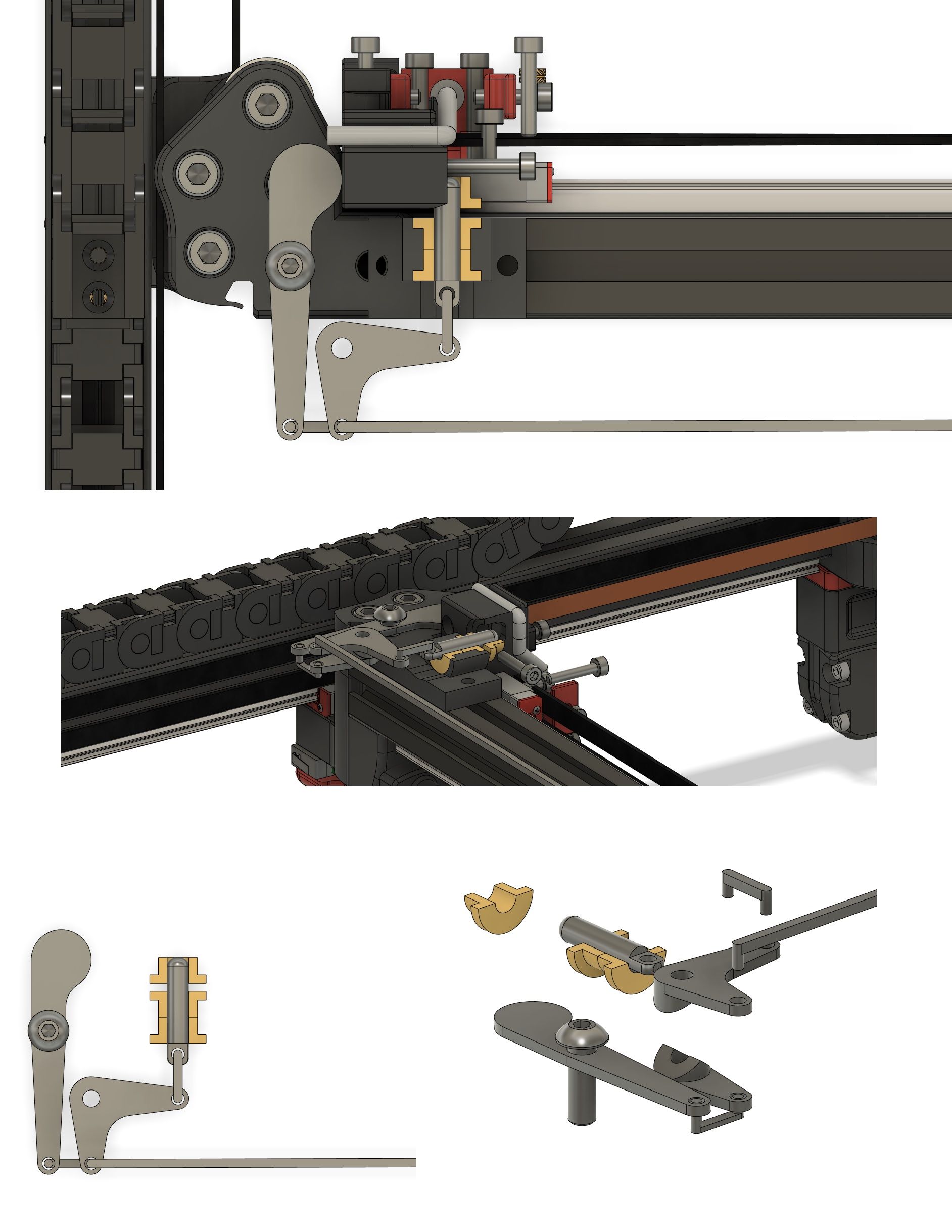
Alrighty, been a busy day, haven’t had much chance to ponder things, but here is my rough idea. It needs a lot more refinement and maybe it can be simplified further but hopefully this is good enough to portray the idea.
There is a brass bush in the carriage where a piece of linear rod can be inserted into to lock it in place.
The far left arm is actuated by the carriage moving to the park position. The secondary idler arm is similar to a servo saver, two seperate arms cut with a v groove allowing the lower arm that’s connected to the carriage actuator to rotate, while the upper arm connected to the locking pin stays in place until the lock pin meets the carriage hole, and snaps into place. A long connecting rod is attached to a mirrored assembly at the other end. Once the lock pin snaps into the parked carriage, it is released simultaneously at the other end.

-
@RichardDuke
If that would work, it had a great advantage over my idea. The beam wouldn't have to travel to the far end, but switch carriers where it is.
But there is one thing, I have doubts. A Servo Saver would store a certain amount of energy, before it can move the pin in the brass bush.
The energy would release, the very moment when the pin fits in the bushing. But at the same time, it tries to pull out the other pin from the bushing. This is only possible by twisting the other Servo Saver because the other side is still locked.
Assuming both Servo Savers have the same spring tension applied, where does the extra energy come from? In my mind, both Servo Savers would stop in the middle, where the forces are equal.
Another point is the push action of the long connecting rod. That's never a good idea, but can be modified to a pull action with a different arm-setup.I hope, I'm wrong. Let's find out by building a Proof_of_Concept thing.
Is there a way to avoid printing the Servo Saver V-grooves? -
@o_lampe ahh yes your right about the energy thing at both ends, it will be equal so it will probably bind up and freeze. But I think it can be altered to accomodate. It is a little bit of a complex system though, electric servos are sounding pretty good at the moment haha
Richard
-
Nice graphics!
Do you do that sort of work professionally?
Frederick
Printers: a E3D MS/TC setup and a RatRig Hybrid. Using Duet 3 hardware running 3.4.6
-
looks like solidworks to me
-
@RichardDuke said in IDEX CoreXY, With Only 2 Motors.:
@o_lampe ahh yes your right about the energy thing at both ends, it will be equal so it will probably bind up and freeze. But I think it can be altered to accomodate. It is a little bit of a complex system though, electric servos are sounding pretty good at the moment haha
My design also failed. Because it has to be symetric in both directions, it doesn't push the switch over the hump.
I watched some videos (for kids) Subject: How a ballpen works. Ran them in slowmotion to see every bit of it. There is a trick how to overcome our dilemma. But I don't see the light yet. Some kind of rotating excenter...a triangle if you will. Let me sleep over it, I have best ideas when I wake up.BTW: Did you know it took 66 engineers to invent the ballpen 1965?