PA: Prusament PETG and Prusa Bear bondtech extruder
-
Greetings,
I am trying to dial in Prusament PETG with pressure advance and I am getting very weird values and indecisive results..
Here is my configuration:
; Configuration file for Duet WiFi (firmware version 3)
; executed by the firmware on start-up
;
; generated by RepRapFirmware Configuration Tool v3.2.3 on Thu Mar 11 2021 17:12:54 GMT+0200 (Eastern European Standard Time)

; General preferences
G90                                                     ; send absolute coordinates...
M83                                                     ; ...but relative extruder moves
M550 P"Prusa Bear MK2.5"                                ; set printer name

; Network
M552 S1                                                 ; enable network
M586 P0 S1                                              ; enable HTTP
M586 P1 S0                                              ; disable FTP
M586 P2 S0                                              ; disable Telnet

; Drives
M569 P0 S1                                              ; physical drive 0 goes forwards
M569 P1 S1                                              ; physical drive 1 goes forwards
M569 P2 S1                                              ; physical drive 2 goes forwards
M569 P3 S1                                              ; physical drive 3 goes forwards
M569 P4 S1                                              ; physical drive 4 goes forwards
M584 X0 Y1 Z2:4 E3                                      ; set drive mapping
M671 X-36.0:290.0 Y110:110 S1                           ; Set the Z motor relative locations correction 1mm
M350 X16 Y16 Z16 E16 I1                                 ; configure microstepping with interpolation
M92 X200.00 Y200.00 Z400.00 E280.00                     ; set steps per mm
M566 X800.00 Y800.00 Z60.00 E3000.00 P1                 ; set maximum instantaneous speed changes (mm/min)
M203 X12000.00 Y12000.00 Z900.00 E6000.00               ; set maximum speeds (mm/min)
M201 X6000.00 Y6000.00 Z200.00 E5000.00                 ; set accelerations (mm/s^2)
M204 P600 T3000						; Set accelerations (mm/s^2) for print and travel moves
M906 X1200 Y1200 Z600 E1200 I30                         ; set motor currents (mA) and motor idle factor in per cent
M84 S30                                                 ; Set idle timeout

; Axis Limits
M208 X0 Y-4 Z0 S1                                       ; set axis minima
M208 X250 Y210 Z210 S0                                  ; set axis maxima

; Endstops
M574 X1 S1 P"xstop"                                     ; configure active-high endstop for low end on X via pin xstop
M574 Y1 S1 P"ystop"                                     ; configure active-high endstop for low end on Y via pin ystop
M574 Z1 S2                                              ; configure Z-probe endstop for low end on Z

; Z-Probe
M558 P1 C"zprobe.in" H0.85 F600 T12000 A3 S0.03         ; set Z probe type to unmodulated and the dive height + speeds
G31 P500 X23 Y5 Z0.975                                  ; set Z probe trigger value, offset and trigger height
M557 X24:228 Y6:210 S50                                 ; define mesh grid

; Heaters
; prusa mk2.5 bed
M308 S0 P"bedtemp" Y"thermistor" T100000 B4092 C0       ; configure sensor 0 as thermistor on pin bedtemp
M950 H0 C"bedheat" T0                                   ; create bed heater output on bedheat and map it to sensor 0
M307 H0 B0 S1.00                                        ; disable bang-bang mode for the bed heater and set PWM limit
M140 H0                                                 ; map heated bed to heater 0
M143 H0 S120                                            ; set temperature limit for heater 0 to 120C
M307 H0 R0.321 C270.9 D10.56 S1.00 V12.7                ; set PID for bed
; e3d hotend
M308 S1 P"e0temp" Y"thermistor" T100000 B4725 C7.06e-8  ; configure sensor 1 as thermistor on pin e0temp
M950 H1 C"e0heat" T1                                    ; create nozzle heater output on e0heat and map it to sensor 1
M307 H1 B0 S1.00                                        ; disable bang-bang mode for heater  and set PWM limit
M143 H1 S300                                            ; set temperature limit for heater 1 to 280C
M307 H1 R2.637 C231.0 D7.78 S1.00 V12.7                 ; set PID for the hotend

; Fans
M950 F0 C"fan0" Q500                                    ; create fan 0 on pin fan0 and set its frequency
M106 P0 S0 H-1                                          ; set fan 0 value. Thermostatic control is turned off
M950 F1 C"fan1" Q500                                    ; create fan 1 on pin fan1 and set its frequency
M106 P1 S1 H1 T45                                       ; set fan 1 value. Thermostatic control is turned on

; Tools
M563 P0 D0 H1 F0                                        ; define tool 0
G10 P0 X0 Y0 Z0                                         ; set tool 0 axis offsets
G10 P0 R0 S0                                            ; set initial tool 0 active and standby temperatures to 0C

; Custom settings are not defined
The printer is a converted Prusa to full Bear including X axis and extruder.
During the python script and slicer PA calibration tests I tried many values but they give me nothing compared to the official guide.
In the guide, direct extruders go for "0.025 and up".
Here is the first test 0.0-0.5:

Another test of 0.1-0.3:

Another test of 0.1-0.2:

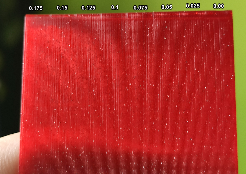
Another test of 0.125-0.175:

Anybody suspects what could be wrong? These values appear way too large for a direct drive extruder. Maybe it's the specifics of PETG? Maybe some of my extruder settings are wrong?
-
IMO the correct PA value is where YOU get the best results.
I'm having the same extruder on a Hypercube Evolution and the best PA value is exactly 0.1 for 'Spectrum PETG'.
I used the same method you did to get the PA-Value.
-
@Murloc992 Try below 0.1, like 0.05 to 0.125. I don't think you're going quite low enough.
Ian
-
I have tried below 0.1 (0.05-0.1) including the PA test prints and regular cube prints.
 Right now I have narrowed it down to 0.13-0.135, going to print some cubes and see what I get.
 -
@Murloc992 Like all these things, there are a lot of variables. PA is there to compensate for pressure (or lack of) inside the hot end. So at the start of a print move, the carriage accelerates, as does the extruder motor. But a rapid change in extruder motor speed, doesn't necessarily translate to rapid change in extruded filament at the nozzle tip, because it takes time to melt the filament and because the filament is a viscous fluid, it takes time before an increase in pressure results in an increase in flow. The net result of all that, is that there is a lag between carriage acceleration and the corresponding acceleration to volume flow leading to under extrusion at the start of a print move. Conversely, during a move, pressure can build up inside the hot end so at the end of a move, the carriage decelerates as does the extruder motor. But the pressure that has built up inside the hot end, continues to force the molten filament out of the nozzle, even though the extruder has started to slow down. So the net result is over extrusion at the end of a move. PA attempts to compensate by increasing the extrusion at the start of a move and decreasing it by the same amount at the end of a move.
So the amount of PA will depend on pressure which in turn depends on the characteristics of the hot end (size of the melt chamber etc, ), the diameter of the nozzle (smaller nozzles will cause higher pressure than larger ones), the viscosity of the filament (which can vary with print temperature), the layer height (lower layer heights use lower flow rates than taller layer heights), the print speed (and more importantly the acceleration), and probably about a dozen other variables if I thought about for longer.
So forget about suggested values because there are too many variables - find and use what works best for you. You'll likely need to use different values for different filaments. -
Thanks for indepth explanation @deckingman
 I suspected as much that I will need to fine tune it a lot and especially for different filaments. Maybe I just grew up spoiled by Linear Advance.
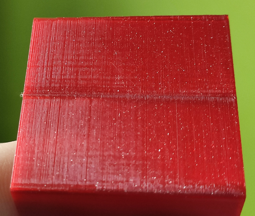
I did another test from another thread, a 2 perimeter 40x40 cube using prusaslicer:


Somehow I feel like something around 0.1 is what I need.

-
@Murloc992 Well AFAIK, Linear Advance (Marlin) and Pressure Advance (RRF) do essentialy the same thing. I have no experience of using linear advance so cannot comment but others have said that the RRF version of pressure advance is harder to tune and get right.
Personally, I tune it by printing the biggest cuboid that I can and as fast as the melt rate of the hot end will allow and with 100% infill. On the basis that the longer the move and the faster the speed, then the more pressure will build. So by simply observing the extrusion at the start and end of each move, one can assess the effect of PA (which you can change "on the fly"). I find that a finger tip is more sensitive than the MK1 eyeball and when PA is right, one can neither see nor feel any difference between the start, mid point, and end of the infill lines. You need to lay down a couple or more layers first to ensure that you have good baseline (literally). That works for me anyway............
-
Toying around I found a easier way to notice what I need to look for.
I just printed 20x20x10(cut in half) 15% grid infilled cubes with no top and seam aligned in the rear, fast prints really.
This allowed me to see how the seam and corners react.
Using MK1 fingers (
 @deckingman ) not MK1 eyeballs I was able to feel the difference and found my perfect value which is 0.11. So if anybody stumbles here with similar setup, feel free to use this as a baseline.
Marking this as solved. What an adventure!
-
@Murloc992 Often the best method is simply the one that works for you. Glad you found the "MK1 finger tip vs MK1 eyeball" tip useful. It gets more useful with age

-
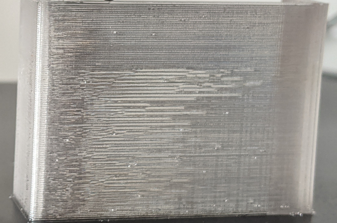
I accidentally found an interesting way to support MK1 eyeball in seeing PA effects -- printing transparent CPE.

This is with a 400mm-ish Bowden setup so PA is a bit higher than with direct extrusion setups.
The print starts with PA 0.1, then goes to PA0, then to 0.2, 0.25, 0.3, 0.33. It's really easy to see even for my tired eyes where PA is better and where it is worse. Results aren't completely conclusive (0.25 looks the best defined, and 0.33 looks a tad shorter but not perfect yet).
You can see both the werd horizontal artifact, and the corner bulge increasing and receeding in line with the PA changes ...
(Yes, I am aware that the actual PA value may change with particular filament's behavior).
-
I have finally dialed in the value. Apparently 0.11 is too much.
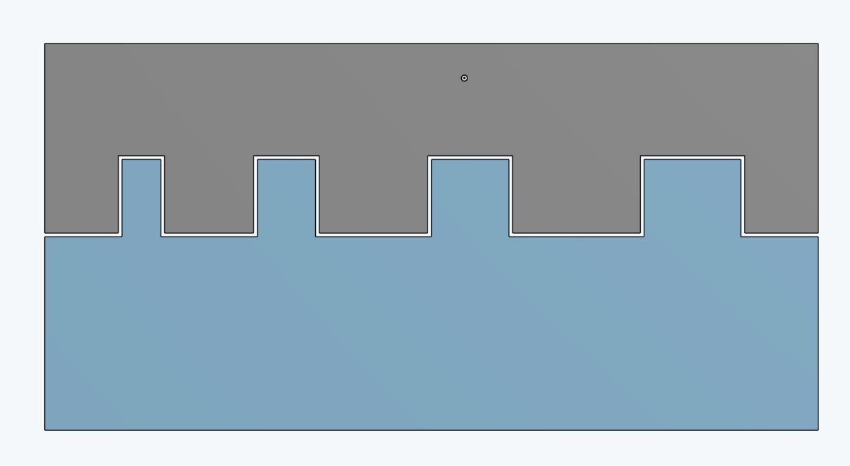
I printed the "toleromancer" a 0.1mm offset test print with 1mm, 1.5mm, 2mm, 2.5mm interlocking features:

This allowed me to fine tune the values with "real world" application: fitment.
0.000 didn't fit, as expected.
0.100 fit but snugly, so not optimal
0.110 fit, but with snugness on the smallest 1mm part, kind of counterintuitive0.105 fit perfectly with 0.1mm tolerance throughout including the 1mm part.
Hereby I present you the Toleromancer: