Closed Loop Motor Setup
-
I wonder what this means from the manual;
13 Pulse command filtering time
Unit: 50us
Range: 0~600
Default: 60

The larger the value, the smoother the motor runs and the noise,
but the position tracking lag time also increases.
50 microseconds times 60 is 3 milliseconds which is a LONG time.
The mention of "the position tracking lag time also increases" makes me think this thing might be accumulating a bunch of input pulses before starting to move the motor depending on whatever it's gains are set to.
But that would make these motors completely unsuitable for CNC or 3D printer applications, so I just don't know.
-
Yes, They all Report Back. I Had to Down Grade Firmware too 3.3Beta1 Because Using 3.3Beta2 Was Causing the Temperature of my Thermocouples to not read anymore.
Good Catch, If these Motors end up being Unusable. Would you or anyone else have a Suitable Option for Replacement? I Thought the Default 60 Meant 60us, Not 50us x 60.
-
How about trying some square motion starting very slowly and getting faster and faster and make sure only one axis moves at a time?
I don't know the size of your machine or where the origin is, but something like this: (Made-up GCODE, you'll need to make real code)
G0 X0 Y0 Z10 G1 X300 F50 G1 Y300 G1 X0 G1 Y0 G1 X300 F100 G1 Y300 G1 X0 G1 Y0 G1 X300 F150 G1 Y300 G1 X0 G1 Y0 G1 X300 F200 G1 Y300 G1 X0 G1 Y0 G1 X300 F250 G1 Y300 G1 X0 G1 Y0 -
Ill give it a shot. Im also Checking into a way of Modifying that setting from 60 to somthing Much Lower. Should that be Lowered to 1? to = 50us
I don't see that as an option. A 3d Printer that can only Print square Objects! lol
-
I'm interested in seeing if when you move very slowly that only one axis moves at time and (maybe) when yo move faster, it's not waiting for the move to complete and starting the next move due to "the position tracking lag..." mentioned above.
That would indicate it's more likely the drives and not a Duet firmware thing.
-
@alankilian Thanks for your help, I really appreciate it!
Alright, Heres what happened.
I Had to change the Speed because the original was moving at 0.5mm Per second. I did Pick Ridiculous Speed Numbers To see what would happen, and the Speed Remained CONSTANT the entire time suggesting the Speed is Controlled by the External Driver?G90 G0 X0 Y0 Z10 G1 X300 F3000 G1 Y300 G1 X0 G1 Y0 G1 X300 F5000 G1 Y300 G1 X0 G1 Y0 G1 X300 F10000 <- Here is where it said the Print was Finished. G1 Y300 G1 X0 G1 Y0 G1 X300 F15000 G1 Y300 G1 X0 G1 Y0 G1 X300 F20000 G1 Y300 G1 X0 G1 Y0Edit: The External Driver Doesn't Fully Control the Speed, But Perhaps the Maximum Speed? When Requesting a Low Speed Like 50, it Moved at 0.5mm Per second. But at 3000, It was moving more like 50mm Per Second.
-
This post is deleted! -
I Just Got the Software to Modify the Settings Built in to the Closed Loop Stepper.
Will change the Motors back and Get back Tomorrow with the Findings
My First Attempt will change the Timing:
13 Pulse command filtering time Unit: 50us Range: 0~600 Default: 60 <- Will Change to 1 = 50us The larger the value, the smoother the motor runs and the noise, but the position tracking lag time also increases. -
Alright Here's what I Found. I was able to use the Software to Communicate with the Drives. Changed the Setting to be MUCH Lower. Also Tried Changing these to act like Regular Stepper Motors. But Nothing I Changed Would Work.
Here's My Options:
1 - I need to Find a way to make EVERY Move Wait for An End Stop to be activated before moving to the next (Seems Slow and Unreasonable) So Im Ditching These Motors Unfortunately.
2 - Find another Nema 23 Closed Loop Motor that WILL Work with Duet 3 1XD.
3 - Continue to Rip Hair out until Bald.
Would Prefer #2 at this Point. Cost is not Much Of an issue. Any Suggestions would be awesome!
-
Well, we don't really know what the problem is with these motor-drivers yet, so I'm reluctant to try any other suggestion.
As an experiment (if you're still willing to experiment) set the drivers for open-loop mode and see how they perform.
- Do they finish the moves as expected?
Can you try slow movements and see if they complete the move at the same time?
What is your microstepping value on the drives?
Do you have steps-per-mm set right?- If you move 20mm, does the axis actually move 20mm?
Laqst one: WHY do you need closed-loop control?
- What are you trying to get out of a closed-loop system that you don't get from an open-loop system?
-
@alankilian Great Questions,
Currently Only the X+Y are using these Motors. I Think this Might work if I also Had All 3 Z Motors using the same Motor as well. (Maybe add the same Delay to all Motors Canceling out any issues?)
With the Software, I Changed the Parameters, Saved them and Read them again to make sure it was saved. After changing the Parameters. It doesn't seam like anything actually changed.
I changed them to Open-Loop Mode and it did not change its behavior at all. Slow Movements Repeated the same Issue.
Micro stepping was turned off. Full Steps Only. The Steps Per mm was also Set correctly, 20mm Was Moved 20mm.
Last, Closed Loop was More of a "Want" Then a "Necessity". I Changed these Motors Out just now for Nema 23 Steppers. I Purchased 2 Duet 3 1XD Boards for Closed Loop, and I was Hoping to Utilize them.
Didn't Think I would have a hard time getting them setup
-
These motors are US$100 for me, so I don't really want to invest US$200 to see if I can figure out what's going on.
Where are you located?
If you are interested, would you send me these motors/drivers and I'll hook them to a logic analyzer and see if I can make them work for you and then send them back?
If you're too far away i understand.
-
Sure I don't mind. They will be sitting around Collecting Dust Otherwise. Do you want me to Send 1 Or Both?
The Software they Gave to Change the Parameters:
ESS ProtunerIm Located in Baltimore, Maryland.
Let me know if you need anything else with them, PM me with the details.
-
OK, moving to PM.
-
@Toastinator I have one drive up and running.
I can read and write the internal motor-controller parameters and (sometimes) they survive a power-cycle.
I am driving the motor from an Arduino so I can precisely control the step pulse count and timing.
I'm capturing data using a Saleae Logic 16 probe so I can see the step pulses and the encoder output as a measure of motor angle.
I'm using a 2000 Count-per-revolution encoder and looking at one phase so I get 500 pulses-per-revolution captured.
I'm seeing things that looks pretty good, but it might be good to get some feedback on what others think.
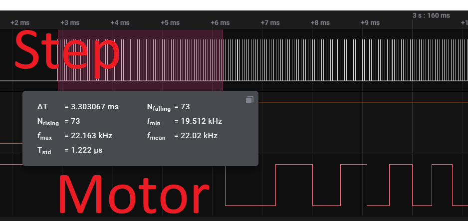
- I'm seeing about 70 step pulses at the beginning of a move before the motor shaft moves. (That's 2.x step at 0.9 degrees-per-step) It seems like this is acceptable for 3D printing.
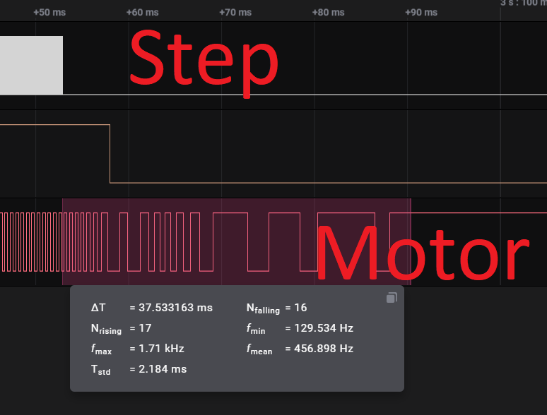
- I see in the neighborhood of 16 encoder pulses at the end of a move after the step signals complete before the motor stops. This is about 12 degrees (13 steps) which seems like a LOT and I would think would cause printing problems.
I'll update so I can capture both encoder signals to see if the motor is oscillating around at the end of a move or if it's actually decelerating and continuing to move in the same direction.
As it stands, I'm not sure these will work for printer drivers (yet)
Setup:

Beginning of move:
End of move:
-
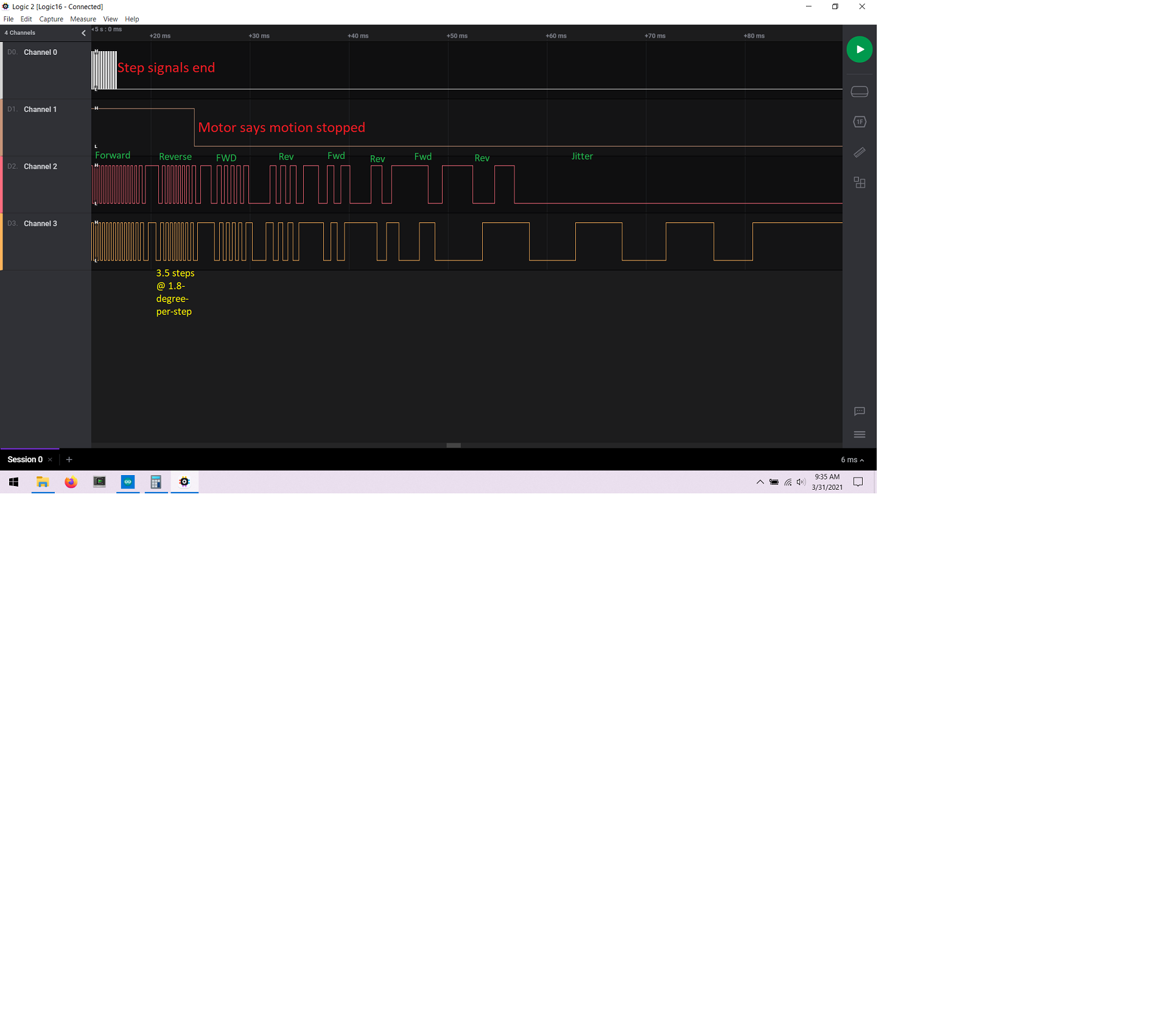
@Toastinator I built a better motor-to-encoder mount and have takes some more data and I'd like some expert thinking about this.
I see when the motor comes to a stop that it takes tens of milliseconds after the step signals end before the motor actually stops moving.
And the motor does a bit of a "Boing" oscillating back-and-forth a few times as it comes to a stop.
I think all these are from the closed-loop control part of the system, not from the stepper motor itself because the magnitude of the "Boing" is greater than 1 step.
Anyway, I'm thinking that this amount of movement and delay-after-stepping-stops won't be visible in a print, but I'm not sure.
ALSO, this is a raw motor connected to an encoder so there's no real mechanical load on the motor at all and it will behave very differently in a real machine.
Will it boing more or less in a real machine? That's impossible to know.
My next step is to connect it to the Duet2/Ethernet and see what it does when asked to move based on Gcode and all the motion-control stuff in RRF.

-
@alankilian
thumbs up for your setup!
But I still don't dig your encoder-coupler. Sure the encoder has almost zero friction/stiction but to me it seems the cosed loop circuit has a PID algorhythm and the flexing? shrinktube introduces the 'boing'.
I'd put a load to the motor, the PID (if there is any) will be less jumpy then. -
@o_lampe That blue encoder is not involved in the closed-loop control.
It's just for monitoring the motor shaft angle.
All the closed-loopidness is done inside the motor itself.I could stick something into the gap and press on the motor shaft a little to add damping and see if it changes the situation.
Of course, a REAL mechanical system will COMPLETELY change the dynamics because there will be actual friction/damping and inertial loads.
What I'm interested in now is will it make any visible defects if:
- It takes 25 milliseconds after the last STEP before motion stops
- If the stop position oscillates like +/- 4 degrees of motor shaft at the target setpoint.
I've got a Delta, so I don't know what a "normal" pully-degrees-per-effector-mm ratio is for a printer.
-
@alankilian said in Closed Loop Motor Setup:
That blue encoder is not involved in the closed-loop control.
The encoder has a rotormass, so there is inertia and the shrinktube 'stores' energy, too. That was what I meant.
-
@alankilian Really Great Job, Hope someone Can Shed some light on what's going on here
Happy Easter Everyone!