New heated enclosure printer
-
Hello all,
I'm about to start on a 3D printer project to print prototype motorcycle bodywork in ABS or ASA maybe with HIPS supports. I have a highly modified replicator2 (if any original parts are left!) that works decently well so am not a complete novice in this undertaking.
I have an unused environmental test chamber that goes -40C to 200C to use as a donor for the chassis/enclosure/heating system.
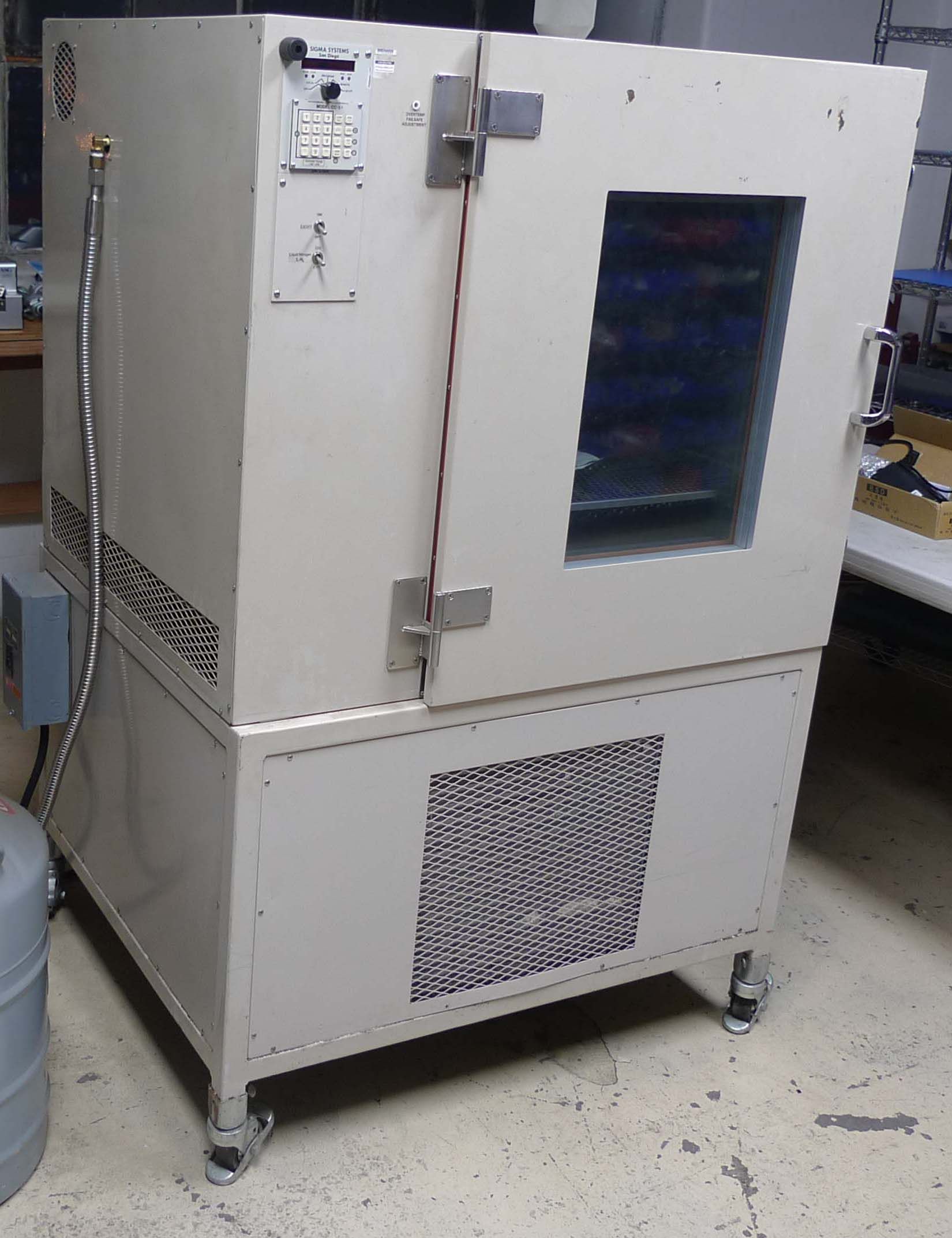
It is thoroughly insulated and has 3200W of heater/fan units that can be reused and I'll gut the refrigeration part. I'm a working mechanical engineer with a full CNC machine shop and have the mechanical design and fabrication needs pretty well covered, but have questions on selecting and integrating all the electronics needed and getting it actually running.
The overall specs are:
-650x650x1000mm print volume
-dual IDEX extruders
-linear rails on all the axes
-ballscrew on the Z
-XY Motors are Teknic ClearPath SDSK servo stepper replacements
-1.75mm E3D Aqua and 24V Super Volcano extruders with a 1mm nozzle and hot end
-filament sensors
-BL Touch sensor with some heat shielding
-130C or so heated bedI wanted to go with a CoreXYU(V?) setup for independent X and slaved Y operation of the second printhead. Looking around, the nomenclature of double printhead CoreXY systems seems a little vague. I intend (I think!) for a 4 motor system, essentially 2 CoreXY on top of each other with a common Y carriage and linked in software.
The chamber heating would reuse the existing units (4 individual 800W 220VAC heater/fan combo units) and control them with relays (SSD?) controlled by a couple of chamber temp sensors. The multi element bed heater (actual parts TBD) also needs to be controlled. My shop is wired for 220VAC power and I have a large 1200W 220VAC-75VDC power supply that can be used for the ClearPath motor power and stepped down to 24V for the hot end heaters and whatever else is needed, and down to 12V or 5V if that is needed anywhere.
The insulated chamber is about the build volume size, so I will have to cut a big hole in the top and the entire mechanical motion assembly will be a subassembly that bolts to the top with Z dropping down into the chamber. I'll use a couple of custom machine way bellows on the X and Y carriages that closely surround the large dual Supervolcano hot ends to contain the chamber hot air and isolate the carriage as much as possible. They will add some drag to the XY motion, but I plan on using overkill-level XY motors so it should not affect operation. The Z rails and leadscrew will be isolated from the build chamber and the table supports will protrude through two slots in the wall. The Z carriage, table supports and table base will be from high temp carbon fiber plate to minimize thermal growth. The actual heated table will be a ground aluminum plate with a semi-floating design to allow thermal movement. Maybe a PEI or PET sheet, or just an ABS slurry.
I'd like to use Duet hardware as it seems to be the most complete system out there, both on the software and hardware level. Can this be done only with a Duet 3 Main Board 6HC? The ClearPath motors take step and direction input, with an external power supply. I'd need an interface screen. Either wired or wireless ethernet. Anything else I am forgetting? I'm not pinching pennies too hard on this project, as it has to work well, and would like the best solution but don't want to waste money for needless complexity.
If anyone is curious, this is all in the service of building a custom race motorcycle and then who knows what. It is a single cylinder roadrace machine with a completely custom frame and suspension and a mostly custom engine. You can see some information on the bike build progress on instagram under @coseng433 or #hypermono or at www.cosentinoengineering.com/blog.
Before I actually start to order parts I'm open for any suggestions or feedback.
Thanks,
Chris
-
@coseng, that sounds like a very interesting project and I will be following anything you post. The BLTouch conks out at about 50C and I am not sure it would appreciate being in a hot chamber even when not in use. I would try and make it removable so that you can run a hot bed but cold chamber when mapping the bed but have it removed when you running your actual prints in the heated environment. Heat shielding will not help you for longer heated chamber runs with the BLTouch installed but maybe a water cooled enclosure for the sensor might (not sure about the sense pin though).
-
@jens55 Thanks! I hope it will be a quickie. I didn't know 50C was the practical knockout temp for a BLTouch. A water cooled holder tapped from the extruder is an option, as is moving it a lot higher with a thin CF rod epoxied to the tip with a guide down at the printhead area to prevent wandering. I emailed them asking what the solenoid could lift and am waiting to hear back. A 1mm CF rod would weight under 0.5g. The extruder and BLTouch would be above the bellows and shielded somewhat from the chamber temp so hopefully it would be enough. With a 50-70C temp rise from ambient, who knows what the table will look like so I'd rather probe with everything at full temp and soaked.
-
@jens55 Seems like I may have jumped the gun assuming the board has step and direction outputs for the xyuv motors. Do you know if that is possible? Or with an expansion board?
-
@coseng, unfortunately I can't help you with that question. Maybe somebody else will chime in.
-
@jens55 OK, thanks. Also received a reply from the BLTouch people:
BLTouch can misunderstand the servo signal when the chamber temperature is over 65C. And an extension to the BLTouch push-pin is a good idea, but because it is not tested I can't surely tell you it might be okay. It might be better that you find a proper weight for your BLTouch by trial and error.
That sounds promising, a tiny CF rod should do it.
Chris
-
@coseng the bellows to insulate the top of high temp printers is sewn from silicone/fiberglass fabric. There may be other manufacturers but Centryco makes them for Stratasys
-
@3dpmicro Thanks for the source. They are not far from a friend of mine so maybe I'll stop by next time I am in the area.
-
@coseng said in New heated enclosure printer:
@jens55 Seems like I may have jumped the gun assuming the board has step and direction outputs for the xyuv motors. Do you know if that is possible? Or with an expansion board?
The 6HC does not provide step and direction outputs for external drivers. The EXP1XD does.
-
@coseng We are using the BLTouch in actively heated chambers above 65c without much issue. Below is from our config. Note A20. It is set that high to combat bad readings, but I don't believe we've ever seen it need to probe more than 5-6 times before an accurate reading is captured.
M558 K0 P9 C"20.io0.in" H3.5 F90 T12000 A20 R0.1 S0.01 -
@oozebot Thanks for the settings. I will try to keep it a bit away from the printhead with a remote sense rod and see how the solenoid reacts to the additional mass.
-
@dc42 >>The 6HC does not provide step and direction outputs for external drivers. The EXP1XD does.
Do you think 4 of them daisy chained would have the bandwidth for the xyuv motors? Is there an upper limit on step rate as you plug in more of them? Not that I want to hack this stuff much but is it not possible to pull the step/dir signals directly from the 6HC board?
-
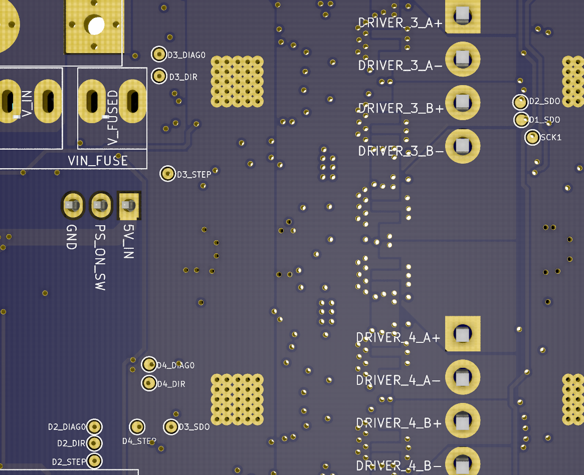
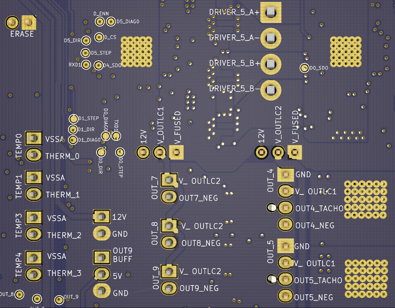
@coseng it's possible to connect to the step and direction signals of the internal drivers, but it's a hack and somewhat tricky. Those signals are available as small circular test pads on the underside of the board. You would need to use fine wires to connect to them. The signal levels are 3.3V at low current, so for most external drivers you would need to use a buffer to shift them to 5V at higher current. Possibilities for this include a Duet 2 Expansion Breakout Board, or a 7406 or 74LS06 chip.
We are working on a Duet 3 main board supporting external drivers, but it isn't ready yet.
There should be enough CAN bandwidth to drive four EXP1XD boards from a MB6HC.
-
@dc42 >>Possibilities for this include a Duet 2 Expansion Breakout Board
That seems like a nice clean solution for the XYUV motors. Doing a motor count, there are 7 total: 2 extruders, 1 Z axis, and XYUV. I saw in one of your other posts that Y and V are slaved together so can I use one of the breakout board's outputs for both the Y and V controller inputs? That would end up with X, Y(V), and U being output as step/dir pulses through the breakout board and Z and the two extruder steppers being driven directly from the 6HC.
-
Just got a bunch of linear rails in from ebay that will take care of all the motion axes.

Once I figure out the motor drive configuration I'll start on the CAD model. It will be as basic as possible to let me get fabricating parts ASAP. -
@dc42 I am comfortable with doing a solder modification to the 6HC to access the step/dir outputs and routing it to a Duet 2 EBB, though the 1XP approach seems neater but has more communications and setup overhead. Which solution do you think would give the best results?
-
@dc42 I hate to bug you, but could you let me know the pads to solder to for the expansion board hack? That is my preferred method for using ecternal drivers if there are no drawbacks besides needing to solder carefully. I want to get all the parts ordered but want to be sure they are the right ones.
-
Note that you will get warnings about issues with the onboard drivers. Also soldering onto the test pads will void your warranty.
-
@t3p3tony Thanks! I understand about voiding the warranty. Are the driver warnings anything to be concerned with in terms of damage to the board or printing issues? I don't want to open a can of worms but being a little old school and given an equal choice, prefer a hardware solution to a software one.
-
@coseng The warnings will be the stepper drivers complaining the is an open circuit between the motor connector pins. This should not cause any damage but be aware those pins will be "live" when the stepper driver is enabled so shorts across them will probably damage the board.
I need to check with @dc42 if M569 R-1 can be used to disable the internal driver without disabling the step and direction signals.
