VFD control options
-
I find with my PWM to analogue converter I get a variation in RPM of around 5-600 RPM.
I currently use heater outputs to control when the spindle is on or off.
Feedback of the speed will allow a lot more control, such as waiting for the spindle to reach speed etc without having to put a delay in the gcode -
It is a shame 0-10V is so widely used in the smaller cheaper drives as it is such a horrible analog signal to use. 4-20mA is becoming much more widely used (and has been for quite some time) as it will fault on cable break and does not worry (Until a certain point) about extra resistance causing voltage drop and therefore incorrect inputs into the VSD.
As I think I mentioned above, I would almost think that an expansion board for VSD control is a good idea with extra inputs and outputs to cover off Start and Stop, Direction, Reference Speed, Digital Input for Current Limit (Mostly for reference as often the VSD is hidden) and current feedback, which can subsequently be used with some form of loop to scale the feed rate down to ensure you do not overload the motor.
Sam
-
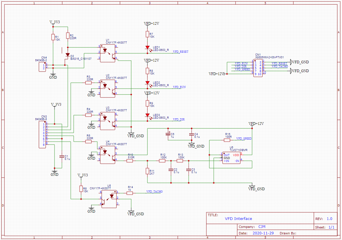
@t3p3tony To answer your question about what "everything" is, the circuit below is an example of a very simple opto-isolated interface that delivers all the key output signals needed to control pretty much any low cost VFD (as far as I can see):
VFD Speed
VFD Run/Stop
VFD Direction
VFD ResetIt is powered on the VFD side by the +12V supply commonly available from such VFD and on the Duet side by the +3.3V supply.
The circuit also provides an opto-isolated input so the Duet can read the tacho pulse from the VFD Frequency connection.
As identified by several people across the Duet3D CNC forum, this would allow:
a) display of the actual spindle RPM on the Duet Web Interface;
b) M3, M4 and M5 commands to wait for the spindle to get to speed before moving to the next G-code command; and
c) adding a feedback loop to be implemented around the VFD to improve spindle RPM stability and control during machining.The current limit and current feedback connections that Sam mentions certainly sound useful, but I haven't come across them in the low cost VFD I've investigated or worked with, so I'm afraid I can't comment on how they could be implemented.
Schematic_VFD Interface_2020-11-19.pdf
I developed this for my own personal use and if it's helpful, anyone may use/develop it as they wish - but no warranties are offered or implied!
-
@cjm said in VFD control options:
The circuit also provides an opto-isolated input so the Duet can read the tacho pulse from the VFD Frequency connection.
In another thread I asked, how fast the external triggers could be read (10kHz?), but @dc42 said, they are not that fast, since they don't run in the main loop.
Do you have different experience? On which pins? -
-
@o_lampe The normal approach to measure the frequency of a repetitive pulse like the VFD tacho with a micro-processor would be to connect it as the clock input to a counter/timer configured to count pulses within a given time window (e.g. 0.1 second). At the end of each time window the timer generates an interrupt and the micro reads the count which is directly proportional to the tacho pulse frequency. In this way, the processor only needs to read the timer count infrequently, without being limited by the micro's code execution.
@T3P3Tony This link describes how to attach a fan with tacho pulse output to either a Duet 2 or 3 so, as you mention, there appears to be hardware provision to read a tacho signal and RPM already:
https://duet3d.dozuki.com/Wiki/Connecting_and_configuring_fans
I wonder if the fan RPM is accessible through the Duet Object Model? If so, then for CNC use, it should be relatively straightforward to repurpose the fan RPM value for spindle speed display on the CNC version of Duet Web Control.
-
@cjm fans.N.rpm is the object model key you are looking for.
-
@t3p3tony Thanks! Hopefully I can try this over the weekend.
-
The above drive manual shows it has a voltage output for frequency feedback. Surely that is a more simple way of getting feedback for rpm.
Sam
-
@samlogan87 The motivations for using a tacho pulse rather than voltage were:
a) it is easier to opto-isolate;
b) if the tacho pulse is derived from the VFD motor drive signal then in principle, the tacho frequency should be precisely related to spindle speed; and
c) it's what I had understood was being output by my VFD's frequency output terminal.However, a little bank holiday tinkering has shown that what my low cost VFD actually provides on its frequency output is not a tacho pulse but a voltage (kudos to Sam!).
It's not a very clean voltage:
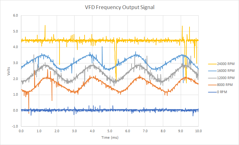
Nonetheless, the DC level appears to be proportional to the displayed spindle RPM:
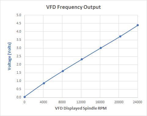
A simple linear fit indicates that the RPM could be calculated from the voltage with an error of roughly +/-300 rpm:
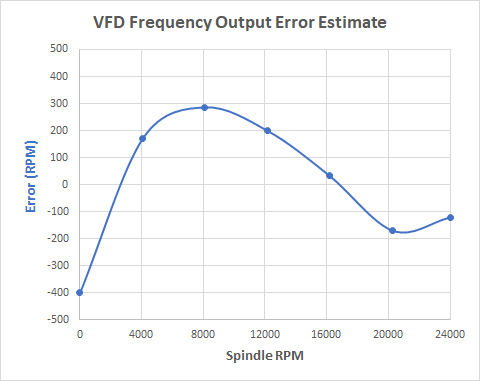
A second order fit roughly halves the error, reducing it to +/-0.6% of full speed:
So, it looks as though this analogue VFD frequency output could give a useful indication of actual spindle RPM.
This leaves the question for "me and my CNC" of how to get this voltage into the Duet, preferably via an opto-isolated interface...
voltage to frequency converter (e.g. LM331) -> opto-isolator -> Duet exp.b6?
Σ-Δ modulator ADC -> isolator -> Duet exp.b6 -> digital filter?
ADC -> isolated spi/i2c? -> Duet spi/i2c?
?
? -
@cjm opto isolation isn’t new with analog signals. We use them a fair bit to protect against burning up plc inputs or vsd inputs and they are generally cheap so shouldn’t be hard to implement. However I have absolutely no experience with designing and build pcb’s so shouldn’t be commenting
Sam
-
@samlogan87 @T3P3Tony
I used an old Arduino to convert my VFD's "frequency output" (0-5.0V) voltage signal into a square wave whose frequency is proportional to the spindle RPM i.e.
VFD 24000 rpm -> 5.0V -> 400Hz square wave.
This square wave drives the Duet's ext.b6 pin via an opto-isolator.The fans[0].rpm object model key gives the following results compared to the demanded M3 rpm and the RPM displayed on the VFD:
M3 S VFD Fans[0].rpm 24000 24000 12000 20000 20154 10150 16000 16169 8123 12000 12118 6103 8000 8154 4117 4000 4083 2090 0 0 0 The fans[0].rpm result look to be half the expected result, presumably due to fans normally having 2 pulses per revolution?
Allowing for this factor of 2, fans[0].rpm tracks the VFD/spindle frequency quite well (~0.3% error).
Ideally one would like to use config.g to define a pin as the spindle tacho source (and an associated scale factor) so that the "Current RPM" could be properly displayed. Might this make be added to a future Duet firmware update?