Duet3D Logo Duet3D
    • Tags
    • Documentation
    • Order
    • Register
    • Login

    How do I set the optical end stop switch?

    Scheduled Pinned Locked Moved
    Duet Hardware and wiring
    7
    18
    2.1k
    Loading More Posts
    • Oldest to Newest
    • Newest to Oldest
    • Most Votes
    Reply
    • Reply as topic
    Log in to reply
    This topic has been deleted. Only users with topic management privileges can see it.
    • kotuoundefined
      kotuo @alankilian
      last edited by

      @alankilian Thank you for your reply.
      The optical end-stop switch that I have now was not purchased.
      Therefore I am unable to post a link to it.

      Originally, this optical end-stop switch was integrated into a Commercially available 3D printer called CZ-300.

      alankilianundefined 1 Reply Last reply Reply Quote 0
      • alankilianundefined
        alankilian @kotuo
        last edited by

        @kotuo Are there any other markings on the switch that could help us tell which side is the LED and which side is the detector?

        SeemeCNC Rostock Max V3 converted to V3.2 with a Duet2 Ethernet Firmware 3.2 and SE300

        kotuoundefined 1 Reply Last reply Reply Quote 0
        • Stephen6309undefined
          Stephen6309 @kotuo
          last edited by

          @kotuo Make sure you're using something that is not transparent to IR.

          kotuoundefined 1 Reply Last reply Reply Quote 0
          • kotuoundefined
            kotuo @alankilian
            last edited by

            @alankilian Thank you for your reply
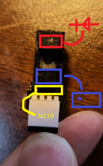
            This picture shows the information that can be found on the surface of an optical end-stop switch.
            From the top.png

            alankilianundefined 1 Reply Last reply Reply Quote 0
            • kotuoundefined
              kotuo @Stephen6309
              last edited by kotuo

              @stephen6309 Thanks for your reply.
              I checked the optical end-stop switch with a black opaque object I had lying around the room.

              1 Reply Last reply Reply Quote 0
              • alankilianundefined
                alankilian @kotuo
                last edited by

                @kotuo OK, connect:
                A to 3.3 Volts
                G to Ground
                C to Zstop-in

                Then see if the LED on the Duet changes state when you put something in the sensor.

                SeemeCNC Rostock Max V3 converted to V3.2 with a Duet2 Ethernet Firmware 3.2 and SE300

                kotuoundefined 1 Reply Last reply Reply Quote 0
                • kotuoundefined
                  kotuo @alankilian
                  last edited by

                  @alankilian Thanks for your reply.
                  We rearranged the cables as shown in the picture.
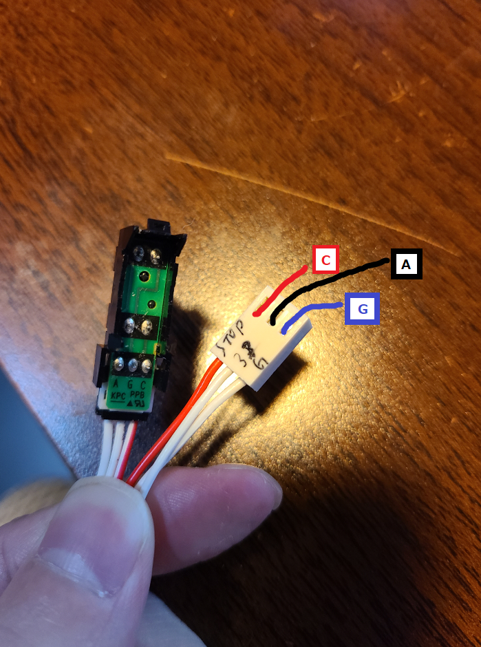
                  Insertion  removal.png
                  The result
                  The end stop switch LED of Duet2 is not shining.

                  alankilianundefined 1 Reply Last reply Reply Quote 0
                  • alankilianundefined
                    alankilian @kotuo
                    last edited by

                    @kotuo If you jumper from G to C with a piece of wire, does the Duet2 LED light up?

                    If so, I'm out of ideas. It can sometimes be easy and sometimes difficult to get an undocumented bit of hardware working.

                    SeemeCNC Rostock Max V3 converted to V3.2 with a Duet2 Ethernet Firmware 3.2 and SE300

                    kotuoundefined 1 Reply Last reply Reply Quote 0
                    • mrehorstdmdundefined
                      mrehorstdmd
                      last edited by

                      @kotuo
                      I recently found that when direct sunlight was hitting my printer one of the optical endstops started misbehaving. A couple small pieces of duct tape on the back sides of the opto interruptor fixed the problem. Apparently sunlight hitting the photodiode from outside the slot can be sufficient to trigger the stop. Maybe that's what's going on with the part you're trying to use. I've been using the optical endstops for a couple years and never had a problem before I moved the printer to a new, sunnier location.

                      Either way, without any data on your part it might not be worth bothering to troubleshoot it when new parts with proper hookup data are readily available and dirt cheap. I use these in my printer- about $3 each, and they have LEDs that indicate when they are activated and maybe more importantly, they have comparators that ensure a "clean" transition from one state to the other. They work fine with the voltage provided by the Duet 2 controller.

                      https://drmrehorst.blogspot.com/

                      kotuoundefined 1 Reply Last reply Reply Quote 2
                      • kotuoundefined
                        kotuo @alankilian
                        last edited by

                        @alankilian Thanks for your reply.
                        From G to C, the Duet2LED lights up when the jumper is finished.
                        I had just borrowed a multimeter from a friend first thing in the morning.
                        Is there any way I can use this to find out what it can tell me?

                        SupraGuyundefined 1 Reply Last reply Reply Quote 0
                        • kotuoundefined
                          kotuo @mrehorstdmd
                          last edited by kotuo

                          @mrehorstdmd Thank you for your reply.
                          It comes with an attachment to avoid direct sunlight, which I will use when I install it.

                          dc42undefined 1 Reply Last reply Reply Quote 0
                          • SupraGuyundefined
                            SupraGuy @kotuo
                            last edited by

                            @kotuo I'd want to check those endstops.

                            I would take the 3V3 and ground, and connect them, then attach a voltage meter between the signal pin and ground.

                            The signal pin should swing between ground and 3V3 when the optical stop is triggered and opened. If it does not, then the endstop is faulty, or you've misidentified the wiring. The optical stops that I have are fitted with an LED which makes diagnosis easier.

                            The labels A G and C are a little ambiguous without documentation. Most RAMPS style boards put the ground in the center, and the signal pin opposite the +VCC. The Duet puts +VCC in the middle. I just swapped the +VCC and Ground pins in the connectors that came with mine, and tested them. The mechanical switches that I had were the same, as they were obviously intended to plug into a RAMPS style board. Could you have A and C mixed up, ie: you're putting current into the signal pin and trying to read the +VCC pin?

                            Lead screw driven printer, powered by Duet 2 Wifi
                            MPCNC powered by Duet 2 Wifi
                            CoreXY printer driven by Duet 3 6HC
                            LowRider CNC powered by Duet 2 Wifi

                            1 Reply Last reply Reply Quote 0
                            • dc42undefined
                              dc42 administrators @kotuo
                              last edited by

                              @kotuo does the optical endstop have a built-in series resistor for the integral IR LED? It would be unusual not to; but can't see one in those photos.

                              Duet WiFi hardware designer and firmware engineer
                              Please do not ask me for Duet support via PM or email, use the forum
                              http://www.escher3d.com, https://miscsolutions.wordpress.com

                              1 Reply Last reply Reply Quote 0
                              • kotuoundefined
                                kotuo
                                last edited by

                                Sorry for the delay!
                                I contacted the manufacturer of my old 3D printer and they told me that the optical end stop switch I have is designed for that purpose only and cannot be used for Duet.
                                I would like to express my sincere thanks to all of you for your co-operation.
                                I think I have not enough experience and knowledge to use this optical end stop switch for Duet, so I would like to use a normally open microswitch which I have prepared as a spare.
                                We'll meet again somewhere else.

                                1 Reply Last reply Reply Quote 0
                                • First post
                                  Last post
                                Unless otherwise noted, all forum content is licensed under CC-BY-SA