How do I set the optical end stop switch?
-
Hello, I am a beginner in electronics using Duet2.
I've been trying to change from a normally open microswitch to an optical end-stop switch, and I've been reading about end-stop switches, but I haven't been able to get it to work.
URL of the reference site
https://duet3d.dozuki.com/Wiki/Connecting_endstop_switches#Section_3_3V_compatible_Hall_sensorHere is the config.g file after changing to the optical end stop switch.
; Configuration file for Duet WiFi (firmware version 3)
; executed by the firmware on start-up
;
; generated by RepRapFirmware Configuration Tool v3.2.3 on Fri May 07 2021 21:10:56 GMT+0900 (日本標準時)

; General preferences
G90                                            ; send absolute coordinates...
M83                                            ; ...but relative extruder moves
M550 P"My Printer"                             ; set printer name

; Network
M552 P0.0.0.0 S1                               ; enable network and acquire dynamic address via DHCP
M586 P0 S1                                     ; enable HTTP
M586 P1 S1                                     ; enable FTP
M586 P2 S1                                     ; enable Telnet

; Drives
M569 P0 S1                                     ; physical drive 0 goes forwards
M569 P1 S0                                     ; physical drive 1 goes backwards
M569 P2 S0                                     ; physical drive 2 goes backwards
M569 P3 S1                                     ; physical drive 3 goes forwards
M584 X0 Y1 Z2 E3                               ; set drive mapping
M350 X16 Y16 Z16 E16 I1                        ; configure microstepping with interpolation
M92 X80.00 Y4000.00 Z80.00 E212.00             ; set steps per mm
M566 X900.00 Y900.00 Z60.00 E300.00            ; set maximum instantaneous speed changes (mm/min)
M203 X2400.00 Y2400.00 Z2400.00 E6000.00       ; set maximum speeds (mm/min)
M201 X500.00 Y500.00 Z20.00 E5000.00           ; set accelerations (mm/s^2)
M906 X800 Y800 Z800 E900 I30                   ; set motor currents (mA) and motor idle factor in per cent
M84 S30                                        ; Set idle timeout

; Axis Limits
M208 X0 Y0 Z0 S1                               ; set axis minima
M208 X300 Y300 Z300 S0                         ; set axis maxima

; Endstops
M574 X2 S1 P"xstop"                            ; configure active-high endstop for high end on X via pin xstop
M574 Y2 S1 P"ystop"                            ; configure active-high endstop for high end on Y via pin ystop
M574 Z2 S1 P"zstop"                            ; configure active-high endstop for high end on Z via pin zstop

; Z-Probe
M558 P0 H5 F120 T6000                          ; disable Z probe but set dive height, probe speed and travel speed
M557 X10:220 Y10:220 S20                       ; define mesh grid

; Heaters
M308 S0 P"bedtemp" Y"thermistor" T100000 B4138 ; configure sensor 0 as thermistor on pin bedtemp
M950 H0 C"bedheat" T0                          ; create bed heater output on bedheat and map it to sensor 0
M307 H0 B1 S1.00                               ; enable bang-bang mode for the bed heater and set PWM limit
M140 H0                                        ; map heated bed to heater 0
M143 H0 S120                                   ; set temperature limit for heater 0 to 120C
M308 S1 P"e0temp" Y"thermistor" T100000 B4138  ; configure sensor 1 as thermistor on pin e0temp
M950 H1 C"e0heat" T1                           ; create nozzle heater output on e0heat and map it to sensor 1
M307 H1 B0 S1.00                               ; disable bang-bang mode for heater  and set PWM limit
M143 H1 S260                                   ; set temperature limit for heater 1 to 260C

; Fans
M950 F0 C"fan0" Q500                           ; create fan 0 on pin fan0 and set its frequency
M106 P0 S0.8 H-1                               ; set fan 0 value. Thermostatic control is turned off
M950 F1 C"fan1" Q500                           ; create fan 1 on pin fan1 and set its frequency
M106 P1 S1 H1 T45                              ; set fan 1 value. Thermostatic control is turned on

; Tools
M563 P0 S"PLA" D0 H1 F0                        ; define tool 0
G10 P0 X0 Y0 Z0                                ; set tool 0 axis offsets
G10 P0 R0 S0                                   ; set initial tool 0 active and standby temperatures to 0C

; Custom settings are not defined

; Miscellaneous
M501                                           ; load saved parameters from non-volatile memory
T0                                             ; select first tool
Optical end stop switches to be used

Reverse side

Please tell me how to solve this problem.
Please let us know if there is any information we are missing. -
What about it doesn't work?
Which wire is connected to which pin on the Duet?
What status does the endstop show when sending M119?
Does breaking the beam change that status?
Does the endstop have an LED on it? Is it lit?
What firmware version are you using? -
@phaedrux Thank you for your reply.
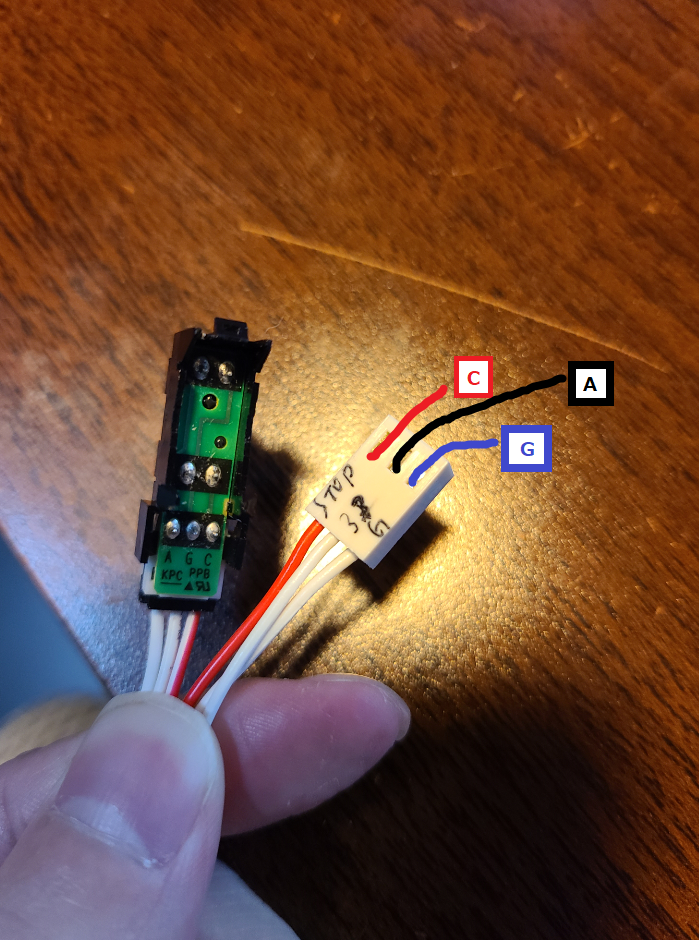
I've connected it to Duet2 as shown in the picture
Here is the firmware version
M115
FIRMWARE_NAME: RepRapFirmware for Duet 2 WiFi/Ethernet FIRMWARE_VERSION: 3.0 ELECTRONICS: Duet Ethernet 1.02 or later FIRMWARE_DATE: 2020-01-03b3
The optical end stop switch itself is not equipped with an LED
The end stop switch LED on Duet2 is not lit.Transmission result of M119
M119
Endstops - X: at max stop, Y: at max stop, Z: at max stop, Z probe: at min stop
Same results after beam failure
-
@kotuo Can you post a link to the optical interrupter you have?
Looking at the circuit board, I suspect it has an LED and a darlington photo transistor in it.
Since it's not working, and I don't know which is which on your PCB, I'm going to guess you need to swap the "A" and "C" connections and probably turn on a pullup in your config.c
But I'm guessing based on a photo and experience, so I could be completely wrong.
-
@alankilian Thank you for your reply.
The optical end-stop switch that I have now was not purchased.
Therefore I am unable to post a link to it.Originally, this optical end-stop switch was integrated into a Commercially available 3D printer called CZ-300.
-
@kotuo Are there any other markings on the switch that could help us tell which side is the LED and which side is the detector?
SeemeCNC Rostock Max V3 converted to V3.2 with a Duet2 Ethernet Firmware 3.2 and SE300
-
@kotuo Make sure you're using something that is not transparent to IR.
-
@alankilian Thank you for your reply
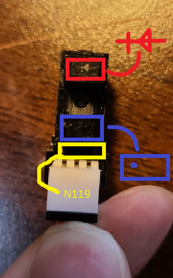
This picture shows the information that can be found on the surface of an optical end-stop switch.
-
@stephen6309 Thanks for your reply.
I checked the optical end-stop switch with a black opaque object I had lying around the room. -
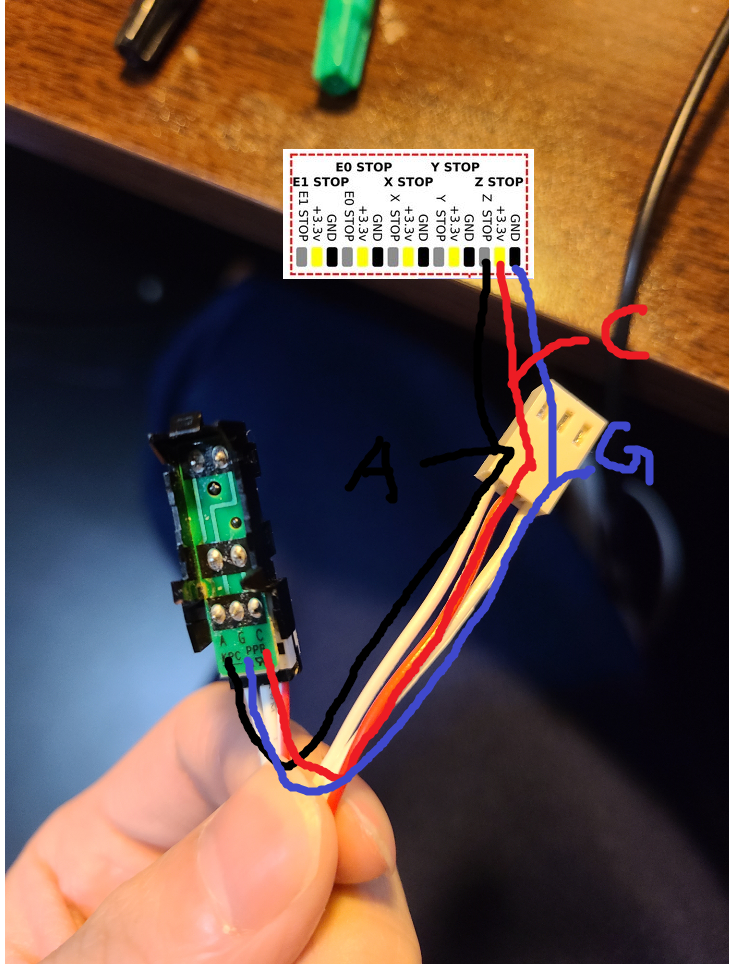
@kotuo OK, connect:
A to 3.3 Volts
G to Ground
C to Zstop-inThen see if the LED on the Duet changes state when you put something in the sensor.
-
@alankilian Thanks for your reply.
We rearranged the cables as shown in the picture.
The result
The end stop switch LED of Duet2 is not shining. -
@kotuo If you jumper from G to C with a piece of wire, does the Duet2 LED light up?
If so, I'm out of ideas. It can sometimes be easy and sometimes difficult to get an undocumented bit of hardware working.
SeemeCNC Rostock Max V3 converted to V3.2 with a Duet2 Ethernet Firmware 3.2 and SE300
-
@kotuo
I recently found that when direct sunlight was hitting my printer one of the optical endstops started misbehaving. A couple small pieces of duct tape on the back sides of the opto interruptor fixed the problem. Apparently sunlight hitting the photodiode from outside the slot can be sufficient to trigger the stop. Maybe that's what's going on with the part you're trying to use. I've been using the optical endstops for a couple years and never had a problem before I moved the printer to a new, sunnier location.Either way, without any data on your part it might not be worth bothering to troubleshoot it when new parts with proper hookup data are readily available and dirt cheap. I use these in my printer- about $3 each, and they have LEDs that indicate when they are activated and maybe more importantly, they have comparators that ensure a "clean" transition from one state to the other. They work fine with the voltage provided by the Duet 2 controller.
-
@alankilian Thanks for your reply.
From G to C, the Duet2LED lights up when the jumper is finished.
I had just borrowed a multimeter from a friend first thing in the morning.
Is there any way I can use this to find out what it can tell me? -
@mrehorstdmd Thank you for your reply.
It comes with an attachment to avoid direct sunlight, which I will use when I install it. -
@kotuo I'd want to check those endstops.
I would take the 3V3 and ground, and connect them, then attach a voltage meter between the signal pin and ground.
The signal pin should swing between ground and 3V3 when the optical stop is triggered and opened. If it does not, then the endstop is faulty, or you've misidentified the wiring. The optical stops that I have are fitted with an LED which makes diagnosis easier.
The labels A G and C are a little ambiguous without documentation. Most RAMPS style boards put the ground in the center, and the signal pin opposite the +VCC. The Duet puts +VCC in the middle. I just swapped the +VCC and Ground pins in the connectors that came with mine, and tested them. The mechanical switches that I had were the same, as they were obviously intended to plug into a RAMPS style board. Could you have A and C mixed up, ie: you're putting current into the signal pin and trying to read the +VCC pin?
-
@kotuo does the optical endstop have a built-in series resistor for the integral IR LED? It would be unusual not to; but can't see one in those photos.
-
Sorry for the delay!
I contacted the manufacturer of my old 3D printer and they told me that the optical end stop switch I have is designed for that purpose only and cannot be used for Duet.
I would like to express my sincere thanks to all of you for your co-operation.
I think I have not enough experience and knowledge to use this optical end stop switch for Duet, so I would like to use a normally open microswitch which I have prepared as a spare.
We'll meet again somewhere else.