Five bar Parallel SCARA print area problem
-
To explain the work modes: every proximal arm has two possible solutions. The workmode tells which one to take. Example:
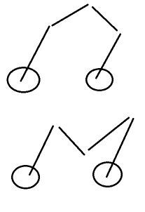
The firmware cannot decide which one to use from the actuator information and arm length information alone. Workmode 1 says to use the first one always.Your last image shows something similar to workmode 3: proximal arms are direction down. Distal arms are looking up. This mode is not supported yet. I wanted to avoid workmodes, but as explained there must be decided somehow which of the two possibilities is the correct one.
-
By singularities and avoid too big actuator distances I mean:
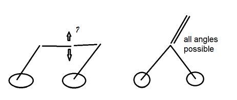
The first one is when the distal arms are horizontally. Then actuator rotation forces the arms to go up or down, which is very bad if you want only workmode 1, distal arms being upward. Another disadvantage if you're near this situation is that the actuators need more force than normal to rotate and the resulting position is less accurate.
The second case is if the proximal arms are rotated so they result in one destination point. Then the distal arms' angle is totally unspecified.
-
@dc42 said in Five bar Parallel SCARA print area problem:
@rutku it looks to mew that X0 Y0 is not reachable on your machine because of its geometry. Does it work if you command it to reachable coordinates?
Yes, it makes limited movements. X 200 -> 185~ Y 29 -> 78
@JoergS5 Thanks, you explained very well like a teacher :).

I did what you said. I still get the same error. My idea is that enstopes should be used and removed once. Because the arms want to move behind. I ordered an optical sensor. I will try it. Because arms want to be free.
config.g
M669 K9 L1 X-95:95 Y0:0 P130:130 D186:186:0:0 B30:30 A15:165:0:360:0:360 C30:270:30:270

; Endstops
M574 X1 S1 P"xstop"   ; X min active high endstop switch
M574 Y1 S1 P"ystop"   ; Y min active high endstop switch
error code:
M120 G91 G1 X10 F6000 G90 M121 Error: G0/G1: target position not reachable from current position -
@rutku G1 X10 means you want to go to a position a bit right (right in the sense of X-Axis direction) of the homing position. This would mean you have to rotate the actuators to an angle smaller 30 degree. This is not allowed (C parameter 30 limit, and your current endstop type).
After homing, please try G1 X-10 first several times to get away from the homing position. Maybe you have to move Y a bit at the same time at the beginning, like G1 X-10 Y10
...limited movements. X 200 -> 185~ Y 29 -> 78
makes sense: the print area is in the diminishing X, and bigger actuator angles mean the hotend moves to a higher Y.Depending on your hardware,
M350 X128 Y128 I1
may be a too high microstepping value. You can check whether you get lost steps by making some movements, then calling M122 and look at the hiccups value. A high number would mean you loose steps. Often 16 microsteps are used, M350 X16 Y16 I1 -
@joergs5 Hi, I did what you said. However, I'm getting the same mistake again. In the output of debug ThetaL: 249.5 ThetaR: 69.45.
config.g
M350 X16 Y16 I1 ;S3 ; Configure microstepping with interpolation
M669 K9 L1 X-95:95 Y0:0 P130:130 D186:186:0:0 B30:30 A15:165:0:360:0:360 C-90:270:-90:270
M92 X115.555556 Y115.555556 ; Set steps per mm
Debug Output
getInverse not cantilevered proximalL:130.00 distalL:186.00 xOrigL:-95.00 yOrigL:0.00 x_0:0.00 y_0:0.00 getTheta getIntersec firstRadius: 130.00 secondRadius: 186.00 firstX: -95.00 firstY: 0.00 secondX: 0.00 secondY: 0.00 getTheta use: 2 x2: -140.64 y2: -121.73 thetaB: 249.45 x1: -140.64 y1: 121.73 thetaA: 110.55 getInverse not cantilevered proximalR:130.00 distalR:186.00 xOrigR:95.00 yOrigR:0.00 x_0:0.00 y_0:0.00 getTheta getIntersec firstRadius: 130.00 secondRadius: 186.00 firstX: 95.00 firstY: 0.00 secondX: 0.00 secondY: 0.00 getTheta use: 2 x2: 140.64 y2: 121.73 thetaB: 69.45 x1: 140.64 y1: -121.73 thetaA: 290.55 getInverse cachedInvalid 0 => cachedX0:0.00 cachedY0:0.00 cachedX1:0.00 cachedY1:0.00 cachedXL:-140.64 cachedYL:-121.73 cachedXR:140.64 cachedYR:121.73 cachedThetaR:69.45 cachedXR:140.64 cachedYR:121.73 cachedThetaL:249.45 cachedXL:-140.64 cachedYL:-121.73 getInverse => cachedInvalid:0 x_0:0.00 y_0:0.00 xL:-140.64 yL:-121.73 thetaL:249.45 xR:140.64 yR:121.73 thetaR:69.45 x1:0.00 y1:0.00 constraintsOK->cachedInvalid:0 actuatorAngleLMin:-90.00<0 && thetaL:249.45>actuatorAngleLMax:270.00 constraintsOK->cachedInvalid:0 thetaL:249.45 < actuatorAngleLMin:-90.00 || thetaL:249.45 > actuatorAngleLMax:270.00 return false constraintsOK->cachedInvalid:0 actuatorAngleRMin:-90.00<0 && thetaR:69.45>actuatorAngleRMax:270.00 constraintsOK->cachedInvalid:0 thetaR:69.45 < actuatorAngleRMin:-90.00 || thetaR:69.45 > actuatorAngleRMax:270.00 return false constraintsOK->cachedInvalid:0 headAngle:180.00 < headAngleMin:15.00 || headAngle:180.00 > headAngleMax:165.00 isnan(headAngle):0 return false -
@rutku said in Five bar Parallel SCARA print area problem:
=> Please comment out the G0 Y0 Y0 line at the end of the homing file, so the values when the endstops are triggered can be controlled.
Then start Duet, and run the homing file. Both endstops must be triggered. Please report M114.
ThetaL and ThetaR should be 30 each at the homing position.
I suspect that the G0 X0 Y0, which is at the end of the homing file, is not reachable. My documentation in https://duet3d.dozuki.com/Guide/Five+Bar+Parallel+SCARA/24#s92 is only a draft of the printable area.
ThetaL: 249.5 (= 180 + 69.5) ThetaR: 69.45.
mean the both arms are nearly in opposite positions, and singularity example 1 of my explanation above is met: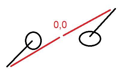
-
@joergs5 How could it be? I have printed almost all values in the FiveBarScaraKinematics.cpp file. I am adding all my settings and outputs again. I am adding the video of the process steps.
config.g
; General preferences
G90 ; Send absolute coordinates...
M83 ; ...but relative extruder moves
M552 S1 ; Turn network on

M586 P0 S1 ; Enable HTTP
M586 P1 S0 ; Enable FTP
M586 P2 S0 ; Enable Telnet

; Drives
M569 P0 S1 ; Drive 0 (X) goes forwards
M569 P1 S1 ; Drive 1 (Y) goes forwards
;M569 P2 S1 ; Drive 2 (Z) goes forwards
;M569 P3 S1 ; Drive 3 (E0) goes forwards
M584 X0 Y1 ; set drive mapping

M350 X16 Y16 I1 ;S3 ; Configure microstepping with interpolation
M669 K9 L1 X-95:95 Y0:0 P130:130 D210:210:0:0 B30:30 A15:165:0:360:0:360 C-90:270:-90:270
M92 X115.555556 Y115.555556 ; Set steps per mm

M203 X10000 Y10000 ; maximum speeds mm/minute

M566 X15 Y15 ; Set maximum instantaneous speed changes (mm/min)
M201 X40 Y40 ; Set accelerations (mm/s^2)
M906 X1200 Y1200 ; Set motor currents (mA) and motor idle factor in per cent

M84 S0 ; Set idle timeout

; Axis Limits
 M208 X-1000:1000 Y-1000:1000 ; set axis minima and maxima

; Endstops
M574 X1 S1 P"xstop"   ; X min active high endstop switch
M574 Y1 S1 P"ystop"   ; Y min active high endstop switch
;M574 Z0 S1 P"zstop"   ; Z min active high endstop switch
home5barscara.g
G91              ; relative positioning

G1 H1 X100 Y300  F900 ; move quickly to endstop and stop there (first pass)
G1 H1 X300 F900
G1 H1 Y300 F900
G1 H2 X-2 Y-2 F900      ; go back a few degrees
G1 H1 X100 F90  ; move slowly to endstop once more (second pass)
G1 H1 Y100 F90  ; move slowly to endstop once more (second pass)
G1 H2 X-5 Y-5 F900      ; go back a few degrees

G92 Z0
G90              ; absolute positioning
G0 X0 Y0 ; move to a reasonable position
outputs:
m115
FIRMWARE_NAME: RepRapFirmware for STM32F4 based Boards FIRMWARE_VERSION: 3.2.2_2 ELECTRONICS: STM32F4 FIRMWARE_DATE: 2021-05-02
ok
WiFi module is connected to access point Utku, IP address 192.168.1.3

MotorStepsToCartesian => thetaL:224.27=MotorPosX:25916.00/StepsPermmX:115.56
MotorStepsToCartesian => thetaR:224.27=MotorPosY:3467.00/StepsPermmY:115.56
getForwad->getIntersec(distalL:210.00,distalR:210.00,xL:-188.08,yL:-90.75,xR:207.58,yR:65.01)
getIntersec firstRadius: 210.00 secondRadius: 210.00 firstX: -188.08 firstY: -90.75 secondX: 207.58 secondY: 65.01
MotorStepsToCartesian => MachinePosX:nan MachinePosY:nan XYZ_AXES:3 numVisibleAxes:3
MotorStepsToCartesian => thetaL:30.00=MotorPosX:3467.00/StepsPermmX:115.56
MotorStepsToCartesian => thetaR:30.00=MotorPosY:3467.00/StepsPermmY:115.56
getForwad->getIntersec(distalL:210.00,distalR:210.00,xL:17.58,yL:65.01,xR:207.58,yR:65.01)
getIntersec firstRadius: 210.00 secondRadius: 210.00 firstX: 17.58 firstY: 65.01 secondX: 207.58 secondY: 65.01
MotorStepsToCartesian => MachinePosX:112.58 MachinePosY:252.29 XYZ_AXES:3 numVisibleAxes:3
MotorStepsToCartesian => thetaL:28.00=MotorPosX:3236.00/StepsPermmX:115.56
MotorStepsToCartesian => thetaR:28.00=MotorPosY:3236.00/StepsPermmY:115.56
getForwad->getIntersec(distalL:210.00,distalR:210.00,xL:19.78,yL:61.04,xR:209.78,yR:61.04)
getIntersec firstRadius: 210.00 secondRadius: 210.00 firstX: 19.78 firstY: 61.04 secondX: 209.78 secondY: 61.04
MotorStepsToCartesian => MachinePosX:114.78 MachinePosY:248.32 XYZ_AXES:3 numVisibleAxes:3
MotorStepsToCartesian => thetaL:30.00=MotorPosX:3467.00/StepsPermmX:115.56
MotorStepsToCartesian => thetaR:30.00=MotorPosY:3236.00/StepsPermmY:115.56
getForwad->getIntersec(distalL:210.00,distalR:210.00,xL:17.58,yL:65.01,xR:209.78,yR:61.04)
getIntersec firstRadius: 210.00 secondRadius: 210.00 firstX: 17.58 firstY: 65.01 secondX: 209.78 secondY: 61.04
MotorStepsToCartesian => MachinePosX:117.53 MachinePosY:249.69 XYZ_AXES:3 numVisibleAxes:3
MotorStepsToCartesian => thetaL:30.00=MotorPosX:3467.00/StepsPermmX:115.56
MotorStepsToCartesian => thetaR:30.00=MotorPosY:3467.00/StepsPermmY:115.56
getForwad->getIntersec(distalL:210.00,distalR:210.00,xL:17.58,yL:65.01,xR:207.58,yR:65.01)
getIntersec firstRadius: 210.00 secondRadius: 210.00 firstX: 17.58 firstY: 65.01 secondX: 207.58 secondY: 65.01
MotorStepsToCartesian => MachinePosX:112.58 MachinePosY:252.29 XYZ_AXES:3 numVisibleAxes:3
MotorStepsToCartesian => thetaL:25.00=MotorPosX:2889.00/StepsPermmX:115.56
MotorStepsToCartesian => thetaR:25.00=MotorPosY:2889.00/StepsPermmY:115.56
getForwad->getIntersec(distalL:210.00,distalR:210.00,xL:22.82,yL:54.94,xR:212.82,yR:54.94)
getIntersec firstRadius: 210.00 secondRadius: 210.00 firstX: 22.82 firstY: 54.94 secondX: 212.82 secondY: 54.94
MotorStepsToCartesian => MachinePosX:117.82 MachinePosY:242.23 XYZ_AXES:3 numVisibleAxes:3
constraintsOK->cachedInvalid:0 cachedX0:0.00 cachedY0:0.00
getInverse not cantilevered proximalL:130.00 distalL:210.00 xOrigL:-95.00 yOrigL:0.00 x_0:117.82 y_0:242.23
getTheta
getIntersec firstRadius: 130.00 secondRadius: 210.00 firstX: -95.00 firstY: 0.00 secondX: 117.82 secondY: 242.23
getTheta use: 2 x2: 22.82 y2: 54.94 thetaB: 25.00 x1: -55.68 y1: 123.91 thetaA: 72.39
getInverse not cantilevered proximalR:130.00 distalR:210.00 xOrigR:95.00 yOrigR:0.00 x_0:117.82 y_0:242.23
getTheta
getIntersec firstRadius: 130.00 secondRadius: 210.00 firstX: 95.00 firstY: 0.00 secondX: 117.82 secondY: 242.23
getTheta use: 2 x2: 212.82 y2: 54.94 thetaB: 25.00 x1: -10.49 y1: 75.98 thetaA: 144.24
getInverse cachedInvalid 0 => cachedX0:117.82 cachedY0:242.23 cachedX1:117.82 cachedY1:242.23
cachedXL:22.82 cachedYL:54.94 cachedXR:212.82 cachedYR:54.94 cachedThetaR:25.00 cachedXR:212.82
cachedYR:54.94 cachedThetaL:25.00 cachedXL:22.82 cachedYL:54.94
getInverse => cachedInvalid:0 x_0:117.82 y_0:242.23 xL:22.82 yL:54.94 thetaL:25.00 xR:212.82 yR:54.94 thetaR:25.00 x1:117.82 y1:242.23
constraintsOK->cachedInvalid:0 actuatorAngleLMin:-90.00<0 && thetaL:25.00>actuatorAngleLMax:270.00
constraintsOK->cachedInvalid:0 thetaL:25.00 < actuatorAngleLMin:-90.00 || thetaL:25.00 > actuatorAngleLMax:270.00 return false
constraintsOK->cachedInvalid:0 actuatorAngleRMin:-90.00<0 && thetaR:25.00>actuatorAngleRMax:270.00
constraintsOK->cachedInvalid:0 thetaR:25.00 < actuatorAngleRMin:-90.00 || thetaR:25.00 > actuatorAngleRMax:270.00 return false
constraintsOK->cachedInvalid:0 headAngle:53.79 < headAngleMin:15.00 || headAngle:53.79 > headAngleMax:165.00 isnan(headAngle):0 return false
constraintsOK->cachedInvalid:0 angleProxDistL:218.10 < proxDistLAngleMin:0.00 || angleProxDistL:218.10 > proxDistLAngleMax:360.00 isnan(angleProxDistL):0 return false
constraintsOK->cachedInvalid:0 angleProxDistR:271.90 < proxDistRAngleMin:0.00 || angleProxDistR:271.90 > proxDistRAngleMax:360.00 isnan(angleProxDistR):0 return false
constraintsOK->cachedInvalid:0 cachedX0:117.82 cachedY0:242.23
CartesianToMotorSteps => motorPosX = cachedThetaL:25.00 * stespPermm[X_AXIS]115.56
 motorPosY = cachedThetaR:25.00 * stepsPermm[Y_AXIS]115.56
CartesianToMotorSteps => machinePos[0]:117.82 machinePos[1]:242.23 motorPosX:0.00 motorPosY:115.56
CartesianToMotorSteps => XYZ_AXES:3 numVisibleAxes:3
constraintsOK->cachedInvalid:0 cachedX0:117.82 cachedY0:242.23
getInverse not cantilevered proximalL:130.00 distalL:210.00 xOrigL:-95.00 yOrigL:0.00 x_0:0.00 y_0:0.00
getTheta
getIntersec firstRadius: 130.00 secondRadius: 210.00 firstX: -95.00 firstY: 0.00 secondX: 0.00 secondY: 0.00
getTheta use: 2 x2: -190.66 y2: -88.03 thetaB: 222.62 x1: -190.66 y1: 88.03 thetaA: 137.38
getInverse not cantilevered proximalR:130.00 distalR:210.00 xOrigR:95.00 yOrigR:0.00 x_0:0.00 y_0:0.00
getTheta
getIntersec firstRadius: 130.00 secondRadius: 210.00 firstX: 95.00 firstY: 0.00 secondX: 0.00 secondY: 0.00
getTheta use: 2 x2: 190.66 y2: 88.03 thetaB: 42.62 x1: 190.66 y1: -88.03 thetaA: 317.38
getInverse cachedInvalid 0 => cachedX0:0.00 cachedY0:0.00 cachedX1:0.00 cachedY1:0.00
cachedXL:-190.66 cachedYL:-88.03 cachedXR:190.66 cachedYR:88.03 cachedThetaR:42.62 cachedXR:190.66
cachedYR:88.03 cachedThetaL:222.62 cachedXL:-190.66 cachedYL:-88.03
getInverse => cachedInvalid:0 x_0:0.00 y_0:0.00 xL:-190.66 yL:-88.03 thetaL:222.62 xR:190.66 yR:88.03 thetaR:42.62 x1:0.00 y1:0.00
constraintsOK->cachedInvalid:0 actuatorAngleLMin:-90.00<0 && thetaL:222.62>actuatorAngleLMax:270.00
constraintsOK->cachedInvalid:0 thetaL:222.62 < actuatorAngleLMin:-90.00 || thetaL:222.62 > actuatorAngleLMax:270.00 return false
constraintsOK->cachedInvalid:0 actuatorAngleRMin:-90.00<0 && thetaR:42.62>actuatorAngleRMax:270.00
constraintsOK->cachedInvalid:0 thetaR:42.62 < actuatorAngleRMin:-90.00 || thetaR:42.62 > actuatorAngleRMax:270.00 return false
constraintsOK->cachedInvalid:0 headAngle:180.00 < headAngleMin:15.00 || headAngle:180.00 > headAngleMax:165.00 isnan(headAngle):0 return false
constraintsOK->cachedInvalid:1 cachedX0:0.00 cachedY0:0.00
getInverse not cantilevered proximalL:130.00 distalL:210.00 xOrigL:-95.00 yOrigL:0.00 x_0:0.00 y_0:0.00
getTheta
getIntersec firstRadius: 130.00 secondRadius: 210.00 firstX: -95.00 firstY: 0.00 secondX: 0.00 secondY: 0.00
getTheta use: 2 x2: -190.66 y2: -88.03 thetaB: 222.62 x1: -190.66 y1: 88.03 thetaA: 137.38
getInverse not cantilevered proximalR:130.00 distalR:210.00 xOrigR:95.00 yOrigR:0.00 x_0:0.00 y_0:0.00
getTheta
getIntersec firstRadius: 130.00 secondRadius: 210.00 firstX: 95.00 firstY: 0.00 secondX: 0.00 secondY: 0.00
getTheta use: 2 x2: 190.66 y2: 88.03 thetaB: 42.62 x1: 190.66 y1: -88.03 thetaA: 317.38
getInverse cachedInvalid 0 => cachedX0:0.00 cachedY0:0.00 cachedX1:0.00 cachedY1:0.00
cachedXL:-190.66 cachedYL:-88.03 cachedXR:190.66 cachedYR:88.03 cachedThetaR:42.62 cachedXR:190.66
cachedYR:88.03 cachedThetaL:222.62 cachedXL:-190.66 cachedYL:-88.03
getInverse => cachedInvalid:0 x_0:0.00 y_0:0.00 xL:-190.66 yL:-88.03 thetaL:222.62 xR:190.66 yR:88.03 thetaR:42.62 x1:0.00 y1:0.00
constraintsOK->cachedInvalid:0 actuatorAngleLMin:-90.00<0 && thetaL:222.62>actuatorAngleLMax:270.00
constraintsOK->cachedInvalid:0 thetaL:222.62 < actuatorAngleLMin:-90.00 || thetaL:222.62 > actuatorAngleLMax:270.00 return false
constraintsOK->cachedInvalid:0 actuatorAngleRMin:-90.00<0 && thetaR:42.62>actuatorAngleRMax:270.00
constraintsOK->cachedInvalid:0 thetaR:42.62 < actuatorAngleRMin:-90.00 || thetaR:42.62 > actuatorAngleRMax:270.00 return false
constraintsOK->cachedInvalid:0 headAngle:180.00 < headAngleMin:15.00 || headAngle:180.00 > headAngleMax:165.00 isnan(headAngle):0 return false
M114 outputs:
m114
X:117.819 Y:242.226 Z:0.000 E:0.000 E0:0.0 Count 2889 2889 0 Machine 117.819 242.226 0.000 Bed comp 0.000
ok
-
This post is deleted! -
@rutku the values seem to be all ok for me.
Homing works, debug tells that the actuators move back 5 degree to 25 like planned, then trying to move to X0 Y0 is not possible because of restriction of parameter A maximum value:
From https://duet3d.dozuki.com/Guide/Five+Bar+Parallel+SCARA/24#s90 :
Annn:mmm:ppp:qqq:rrr:sss nnn is the minimum angle between the distal arms (constr in the first image) in degrees, mmm the maximum....Your setting is 165 degree maximum angle of distal arms, and X0 Y0 is only reachable with distal arms nearly straight line.
line 131 confirms this check:
constraintsOK->cachedInvalid:0 headAngle:180.00 < headAngleMin:15.00 || headAngle:180.00 > headAngleMax:165.00 isnan(headAngle):0 return false -
@joergs5 Yes! Worked!
")
Work Mode 1 but the arms worked at different angles. They work in a very limited area. Could it be from the location of the endstops?
config.g
M669 K9 L1 X-95:95 Y0:0 P130:130 D200:200:0:0 B30:30 A0:180:0:360:0:360 C0:270:0:270
-
@rutku your actuators are 190 away (X -95 to X 95), the proximal arms have length 260, distal arms have length 400, so you cannot rotate to the position of horizontal arms 180/0 degree, because the distance of proximal+distance is 190+260 = 450, and your distal arms are not long enough "to close the gap".
Your video starting at 1:16 the angle of the distal arms is again near 180 degree and violates the A max value parameter.(I see you changed A to 180. The limit will be the arm lengths). A "secure" area is when the arms are forward, like 90 degree both.To clarify: you place the endstops at one location and the B parameter must tell the firmware the correct angle for this endstops. Because when you turn on the Duet, he doesn't know at what position the arms and steppers are. Homing has only one task: tell the firmware at which arm/stepper position the endstop is triggered, then set a value. Kinematics like Cartesian/CoreXY set the value of G1 H1 movements to the M208 value, but here it is set to the value of the B parameter.
The procedure I follow when I am not sure where the print area is:
- home with both actuators endstop 30 degree
- move to an area which is "secure" like G1 X-50 Y20 (relative) (or measure where the absolute coordinate is where both proximal arms are 90 degree)
- from there mark where you can move with small G1 in every direction
I assembled a pen as "hotend" and draw on a sheet of paper.
-
@rutku with your position in video at 1:11:
When you try to move X10, this is not possible: you could turn the left arm up (to a lower angle) and right arm to a low one, but this movement crosses the singularity of unprintable area (the 400 too short for the 450). When a G0/G1 move is done, the kinematics checks whether the movement path is reachable the hole path.
BTW: you could reach your destination if you move the hotend to a high Y value first, then approaching the goal. This is a risk later, when printing an object, because reachability depends on where you start. In other words it depends on how the slicer wants to draw the lines. Later for printing it is better to restrict M208 to a safe rectangular print area and print only in this area.
Please see
https://forum.duet3d.com/topic/10409/joergs5-parallel-five-bar-scara/30
for the complex print area, where some areas on the Y0 line or near it is not printable. -
@joergs5 Hello, I did what you said. I set the right arm to 90 degrees and the left arm to 45 degrees. I used optical endstop. It worked great. G0 X0 Y0 position is not wrong?
Is @bondus repository up to date? I tried but there was no change.
config.g
M350 X16 Y16 I1 ;S3 ; Configure microstepping with interpolation
M669 K9 L1 X-95:95 Y0:0 P130:130 D200:200:0:0 B45:45 A0:180:0:360:0:360 C-180:270:-180:270
M92 X115.555556 Y115.555556 ; Set steps per mm
-
@rutku G0 X0 Y0 is probably not reachable.
Do you have a question for the debug_output or video?
-
@joergs5 Hi, working mode 1 is selected but the levers like working mode 2 are moving. I made the angle of Constr "0: 180" degrees "15: 165" degrees. Nothing changed. I wanted to show it with video and output.
I wanted to draw 20x20 squares. But very different shape appeared. What is the reason?


Thank you so much for your patience. You have been very helpful.
-
@rutku there must be something wrong with the setup, because your X0 is close to the first wheel, but should be in the middle between the wheels. This change in coordinates produces the curved lines.
Maybe your homing didn't work like before, please check the angles and position when you finished homing (without the last G0 X0 Y0 line).
After homing please try to go to absolute coordinate
G90 G0 X0 Y50
and verify that the position is in the middle between the two big wheels.If you homing angles are correct, but the X0 Y50 is at the wrong place, you can check
- whether the gear ratio and M92 are correctly calculated
- the arm lengths are correct. The length is always from the middle of a hinge to middle of the other hinge
- whether the endstop positions are 45 degree, like is set in config now
-
I followed this thread with great interest, but it got stuck in the middle...are all problems solved?
What was the solution and final layout?I ask, because I look for an excuse to build a fancy Capstan geared drive, either for a SCARA or robot arm.
I'd use Aramid fishing line instead of steel cable and spur and pinion gear hardware from the orbiter/BMG extruder. -
@o_lampe I didn't hear from rutku, but the firmware is ok so far, bondus has made a working scara here: https://hackaday.com/2020/03/18/a-practical-dual-arm-scara-3d-printer/ And if you find a bug, tell me, I'll fix it.
The Capstan is interesting for robot gear also, but 1:30 is difficult to achieve with one stage, because you need a very big wheel. Therefore I use 2 stage gears 1:3 (or 1:2) and 1:10. Please go ahead!
-
@joergs5 @o_lampe
Hi, I didn't get the calibration. I've been dealing with a week calibration but draws the same shapes. @bondus had not shared a detail about calibration. I didn't mean to bother @JoergS5 on that.I didn't understand the "Step Calibration" portion in the file where the bond is shared.
-
@rutku the step calibration in the link mentioned is to calculate the M92 values.
What is the number of teeth of your small and big pulley, is it a standard 200 step stepper and the microstep settingis 16? The goal is to calculate how many steps are needed to rotate by 1 degree. Please tell the numbers, then I will help calculating.
The google calc provided in the link is readonly, but the formula is:
microsteps / stepperdeg * bigwheelteeth / smallwheelteeth
The result is the M92 value.
Example: 16 microsteps, stepper 1.8 degree for one step (= stepper with 200 steps, 360/200 = 1.8), 200 teeth bigwheel, 20 teethsmallwheel => 16/1.8*200/20 = 88.88888