Five bar Parallel SCARA print area problem
-
@rutku with your position in video at 1:11:
When you try to move X10, this is not possible: you could turn the left arm up (to a lower angle) and right arm to a low one, but this movement crosses the singularity of unprintable area (the 400 too short for the 450). When a G0/G1 move is done, the kinematics checks whether the movement path is reachable the hole path.
BTW: you could reach your destination if you move the hotend to a high Y value first, then approaching the goal. This is a risk later, when printing an object, because reachability depends on where you start. In other words it depends on how the slicer wants to draw the lines. Later for printing it is better to restrict M208 to a safe rectangular print area and print only in this area.
Please see
https://forum.duet3d.com/topic/10409/joergs5-parallel-five-bar-scara/30
for the complex print area, where some areas on the Y0 line or near it is not printable. -
@joergs5 Hello, I did what you said. I set the right arm to 90 degrees and the left arm to 45 degrees. I used optical endstop. It worked great. G0 X0 Y0 position is not wrong?
Is @bondus repository up to date? I tried but there was no change.
config.g
M350 X16 Y16 I1 ;S3 ; Configure microstepping with interpolation
M669 K9 L1 X-95:95 Y0:0 P130:130 D200:200:0:0 B45:45 A0:180:0:360:0:360 C-180:270:-180:270
M92 X115.555556 Y115.555556 ; Set steps per mm
-
@rutku G0 X0 Y0 is probably not reachable.
Do you have a question for the debug_output or video?
-
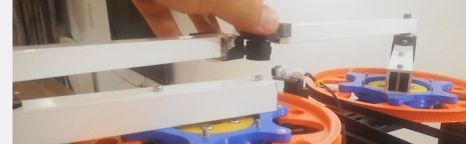
@joergs5 Hi, working mode 1 is selected but the levers like working mode 2 are moving. I made the angle of Constr "0: 180" degrees "15: 165" degrees. Nothing changed. I wanted to show it with video and output.
I wanted to draw 20x20 squares. But very different shape appeared. What is the reason?


Thank you so much for your patience. You have been very helpful.
-
@rutku there must be something wrong with the setup, because your X0 is close to the first wheel, but should be in the middle between the wheels. This change in coordinates produces the curved lines.
Maybe your homing didn't work like before, please check the angles and position when you finished homing (without the last G0 X0 Y0 line).
After homing please try to go to absolute coordinate
G90 G0 X0 Y50
and verify that the position is in the middle between the two big wheels.If you homing angles are correct, but the X0 Y50 is at the wrong place, you can check
- whether the gear ratio and M92 are correctly calculated
- the arm lengths are correct. The length is always from the middle of a hinge to middle of the other hinge
- whether the endstop positions are 45 degree, like is set in config now
-
I followed this thread with great interest, but it got stuck in the middle...are all problems solved?
What was the solution and final layout?I ask, because I look for an excuse to build a fancy Capstan geared drive, either for a SCARA or robot arm.
I'd use Aramid fishing line instead of steel cable and spur and pinion gear hardware from the orbiter/BMG extruder. -
@o_lampe I didn't hear from rutku, but the firmware is ok so far, bondus has made a working scara here: https://hackaday.com/2020/03/18/a-practical-dual-arm-scara-3d-printer/ And if you find a bug, tell me, I'll fix it.
The Capstan is interesting for robot gear also, but 1:30 is difficult to achieve with one stage, because you need a very big wheel. Therefore I use 2 stage gears 1:3 (or 1:2) and 1:10. Please go ahead!
-
@joergs5 @o_lampe
Hi, I didn't get the calibration. I've been dealing with a week calibration but draws the same shapes. @bondus had not shared a detail about calibration. I didn't mean to bother @JoergS5 on that.I didn't understand the "Step Calibration" portion in the file where the bond is shared.
-
@rutku the step calibration in the link mentioned is to calculate the M92 values.
What is the number of teeth of your small and big pulley, is it a standard 200 step stepper and the microstep settingis 16? The goal is to calculate how many steps are needed to rotate by 1 degree. Please tell the numbers, then I will help calculating.
The google calc provided in the link is readonly, but the formula is:
microsteps / stepperdeg * bigwheelteeth / smallwheelteeth
The result is the M92 value.
Example: 16 microsteps, stepper 1.8 degree for one step (= stepper with 200 steps, 360/200 = 1.8), 200 teeth bigwheel, 20 teethsmallwheel => 16/1.8*200/20 = 88.88888 -
microsteps = 128
stepper Degree = 1.8
Teeth bigwheel = 260
Teeth smallwheel = 20M92 = (128/1.8) * (260/20) = 924.444444
square.gcode
G90
G1 X0 Y90
G1 X0 Y140
G1 X50 Y140
G1 X50 Y90
G1 X0 Y90


-
@rutku there are some ideas you can check:
- after your tests, please make M122 and check for hiccups. 128 microsteps could mean you loose steps => correction: I remember you're using hardware which will not report hiccups. You can try to reduce microsteps, but then changing M92 also. You can reduce speed with F parameter (eg G91 G1 H2 X10 F100) also without changing the values and check whether the lines are better then. Reducing speed gives your controller more time to calculate the segments.
- you can verify that your setting are correct by testing:
Home axis 1 to let's say 45 degree (to verify: M669 B first value is 45, arm is at 45 degree position after homing). Make M114 and check the first value of the Count values. This must be M92 value * degree, i.e. 924.4444 * 45 = 41600. Please rotate the axis to example 90 degree (with G91 G1 H2 X90)and make M114 again, the Count value should now be 83200 and the arm should be at 90 degree position.
You can verify additionally the resulting position: verify that the (0,50) position is 5 cm away from your x axis and in the middle of the two wheels. I cannot see it in your image, but the (50,90) and (50,140) must be on the vertical line between the wheels.
Having correct angles is critical for your line precision (straight or curved), so please measure exaclty. I used this idea:
https://forum.duet3d.com/topic/14996/five-bar-parallel-scara-prototypes/10
Another thing to check is whether your arms lengtsh are correct, please verify the lengths:
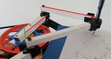
The red lines are the lenghts, from middle of hinge to middle of other hinge. The green line is the starting point of the first line.
-
@joergs5 said in Five bar Parallel SCARA print area problem:
The Capstan is interesting for robot gear also
The good thing about Capstan is, you don't have to print a big wheel with precise teeth. I also had good experience with Aramid line in a non-slipping config. I think it will run really smooth (no tooth-mesh problems)
I should start a new thread about it. -
@joergs5 Hi, I have done the steps you say. But I have received different results.


m122
m122
=== Diagnostics ===
RepRapFirmware for STM32F4 based Boards version 3.2.2_2 running on STM32F4
Used output buffers: 1 of 40 (11 max)
=== RTOS ===
Static ram: 32296
Dynamic ram: 60988 of which 380 recycled
Never used RAM 18200, free system stack 214 words
Tasks: NETWORK(ready,144) HEAT(blocked,369) MAIN(running,572) IDLE(ready,19)
Owned mutexes: WiFi(NETWORK) USB(MAIN)
=== Platform ===
Last reset 00:11:55 ago, cause: [power on/off]
Last software reset at 2021-05-19 00:16, reason: User, GCodes spinning, available RAM 18200, slot 2
Software reset code 0x0003 HFSR 0x00000000 CFSR 0x00000000 ICSR 0x00454000 BFAR 0xe000ed38 SP 0x00000000 Task MAIN Freestk 0 n/a
Error status: 0x00
Aux0 errors 0,134218187,134218187
MCU temperature: min 31.6, current 42.0, max 42.5
Driver 0: position 48996, standstill, SG min/max 0/32, error r/w 0/0, ifcnt 16, cnt r/w 61932/16, timeout 0, failedOp 0xff
Driver 1: position 83200, standstill, SG min/max 0/40, error r/w 0/0, ifcnt 17, cnt r/w 61931/17, timeout 0, failedOp 0xff
Driver 2: position 0, standstill, SG min/max 0/0, error r/w 0/0, ifcnt 9, cnt r/w 61938/9, timeout 0, failedOp 0xff
Driver 3: position 0, standstill, SG min/max 0/0, error r/w 0/0, ifcnt 9, cnt r/w 61938/9, timeout 0, failedOp 0xff
Driver 4: position 0
Driver 5: position 0
Driver 6: position 0
Driver 7: position 0
Driver 8: position 0
Driver 9: position 0
Driver 10: position 0
Date/time: 2021-05-29 13:37:04
Slowest loop: 17.76ms; fastest: 0.07ms
=== Storage ===
Free file entries: 10
SD card 0 detected
SD card longest read time 2.8ms, write time 0.0ms, max retries 0
=== Move ===
DMs created 83, maxWait 328438ms, bed compensation in use: none, comp offset 0.000
=== DDARing ===
Scheduled moves 6, completed moves 6, hiccups 0, stepErrors 0, LaErrors 0, Underruns [0, 0, 0], CDDA state -1
=== Heat ===
Bed heaters = -1, chamberHeaters = -1
=== GCodes ===
Segments left: 0
Movement lock held by null
HTTP is idle in state(s) 0
File is idle in state(s) 0
USB is ready with "m122" in state(s) 0
Aux is idle in state(s) 0
Trigger is idle in state(s) 0
Queue is idle in state(s) 0
LCD is idle in state(s) 0
Daemon is idle in state(s) 0
Autopause is idle in state(s) 0
Code queue is empty.
=== Network ===
Slowest loop: 7.11ms; fastest: 0.00ms
Responder states: HTTP(0) HTTP(0) HTTP(0) HTTP(0)
HTTP sessions: 1 of 8
- WiFi -
Network state is active
WiFi module is connected to access point
Failed messages: pending 0, notready 0, noresp 0
WiFi firmware version 1.25-01S-D
WiFi MAC address 50:78:b3:f3:41:84
WiFi Vcc 3.38, reset reason Turned on by main processor
WiFi flash size 4194304, free heap 36832
WiFi IP address 192.168.1.20
WiFi signal strength -73dBm, mode 802.11n, reconnections 0, sleep mode modem
Clock register 00004002
Socket states: 0 0 0 0 0 0 0 0
ok
config.g
M350 X128 Y128 I1 ;S3 ; Configure microstepping with interpolation
M669 K9 L1 X-95:93 Y0:0 P126:133 D210:213:0:0 B53:90 A15:165:0:360:0:360 C-90:90:-90:90
M92 X924.444444 Y924.444444 ; Set steps per mm
m114
m114
X:-24.654 Y:310.557 Z:0.000 E:0.000 E0:0.0 Count 48996 83200 0 Machine -24.654 310.557 0.000 Bed comp 0.000
ok
924.444444 * 53 = 48.995,55532 OK....!
G91 G1 H2 X90
G91 G1 H2 X90

MotorStepsToCartesian => thetaL:143.00=MotorPosX:132196.00/StepsPermmX:924.44
MotorStepsToCartesian => thetaR:143.00=MotorPosY:83200.00/StepsPermmY:924.44
getForwad => getIntersec(distalL:210.00,distalR:213.00,xL:-195.63,yL:75.83,xR:93.00,yR:133.00)
getIntersec firstRadius: 210.00 secondRadius: 213.00 firstX: -195.63 firstY: 75.83 secondX: 93.00 secondY: 133.00
getTurn => turn:-44706.59 = (x2:-82.95 - x1:-195.63) * (y3:133.00 - y1:75.83) - (y2:253.04 - y1:75.83) * (x3:93.00 - x1:-195.63)
getTurn => turn:44706.59 = (x2:-23.91 - x1:-195.63) * (y3:133.00 - y1:75.83) - (y2:-45.05 - y1:75.83) * (x3:93.00 - x1:-195.63)
getTurn => turn:-26376.60 = (x2:-195.63 - x1:-95.00) * (y3:253.04 - y1:0.00) - (y2:75.83 - y1:0.00) * (x3:-82.95 - x1:-95.00)
getTurn => turn:23401.72 = (x2:93.00 - x1:93.00) * (y3:253.04 - y1:0.00) - (y2:133.00 - y1:0.00) * (x3:-82.95 - x1:93.00)
getForwad => workmode:1 turnLeft:-26376.60 turnRight:23401.72
MotorStepsToCartesian => MachinePosX:nan MachinePosY:nan XYZ_AXES:3 numVisibleAxes:3ok

MotorStepsToCartesian => thetaL:143.00=MotorPosX:132196.00/StepsPermmX:924.44
MotorStepsToCartesian => thetaR:143.00=MotorPosY:83200.00/StepsPermmY:924.44
getForwad => getIntersec(distalL:210.00,distalR:213.00,xL:-195.63,yL:75.83,xR:93.00,yR:133.00)
getIntersec firstRadius: 210.00 secondRadius: 213.00 firstX: -195.63 firstY: 75.83 secondX: 93.00 secondY: 133.00
getTurn => turn:-44706.59 = (x2:-82.95 - x1:-195.63) * (y3:133.00 - y1:75.83) - (y2:253.04 - y1:75.83) * (x3:93.00 - x1:-195.63)
getTurn => turn:44706.59 = (x2:-23.91 - x1:-195.63) * (y3:133.00 - y1:75.83) - (y2:-45.05 - y1:75.83) * (x3:93.00 - x1:-195.63)
getTurn => turn:-26376.60 = (x2:-195.63 - x1:-95.00) * (y3:253.04 - y1:0.00) - (y2:75.83 - y1:0.00) * (x3:-82.95 - x1:-95.00)
getTurn => turn:23401.72 = (x2:93.00 - x1:93.00) * (y3:253.04 - y1:0.00) - (y2:133.00 - y1:0.00) * (x3:-82.95 - x1:93.00)
getForwad => workmode:1 turnLeft:-26376.60 turnRight:23401.72
MotorStepsToCartesian => MachinePosX:nan MachinePosY:nan XYZ_AXES:3 numVisibleAxes:3
m114
m114
X:9999.900 Y:9999.900 Z:0.000 E:0.000 E0:0.0 Count 132196 83200 0 Machine 9999.900 9999.900 0.000 Bed comp 0.000
ok
132196 / 924.44444 = 143,0004814567331 degree .Why?
")

-
@rutku said in Five bar Parallel SCARA print area problem:
G91 G1 H2 X90
ok, first, I made a fault for testing: G91 means relative, but I wanted the arm to rotate to the 90 degree position, so this must be G90 G1 H2 X90.
The relative rotation means 53 degree plus 90, which is your 143 degree (the Count value is about 132T). But the arm seems to rotate into the wrong direction, so 53-90 = -37 degree, which looks correct of the arm position in the image*). Please change the S0 / S1 value for the stepper definition and retry.
If it's
M569 P0 S1 ; Drive 0 (X) goes forwards
then please change to
M569 P0 S0
or other round.*) on the image the arm rotated to position 141, but it should be 143, so you can make the M92 value a bit higher. But I don't know the reason, can be some error in arm length or hinge play.
-
@joergs5 Hi, yes the problem is solved. Completed the movement as you say. But when I want to draw a square, the machine works on the back section.
@joergs5 said in Five bar Parallel SCARA print area problem:
M569 P0 S1 ; Drive 0 (X) goes forwards

sqaure.gcode
G90
G1 X0 Y90
G1 X0 Y140
G1 X50 Y140
G1 X50 Y90
G1 X0 Y90
SQUARE VIDEO
@joergs5 said in Five bar Parallel SCARA print area problem:
on the image the arm rotated to position 141, but it should be 143, so you can make the M92 value a bit higher. But I don't know the reason, can be some error in arm length or hinge play.
There is some curvature in angle gauge. showing two degrees missing.
-
This post is deleted! -
This post is deleted! -
This post is deleted! -
The following tests are to verify that the arms are rotating correctly and an idea about the reason for the curved lines. Arm 1 is the upper arm in the images which is connected to the wheel, arm 2 the lower arm, so only watching the proximal arms. With hotend I mean your pencil position in your case.
You're still using 128 microsteps, so please add F200 to all the following G1 commands, so the processor has more time to calculate values and to generate the steps. Hiccups (= lost steps) will probably not being reported by your hardware.
Step1: (check direction and M92)
- run homing, arm 1 shall be 53 degree, arm 2 90 degree
- run G90 G1 H2 X90 F200 and verify that arm 1 is 90 degree now and rotated counterclockwise
- run G90 G1 H2 Y70 F200 and verify that arm 2 is 70 degree now and rotated clockwise
If one or both arms rotated wrong, change S0 to S1 or S1 to S0 for the corresponding stepper (P0, P1) and redo the test until the arms rotate as expected. If the resulting degree is wrong, search the reason. One possible reason is if the belts have too low tension. Another one is too much play in the hinges. A third possibility is that the arm approaches the endstop too fast, so the angle is not set correctly. Then set the F parameter lower in the line which is commented "approach endstop slowly". The endstops must be approached from the same side always (always from left or always from right), because they trigger at different positions. You may want to change G1 H2 X-2 Y-2 F900 to a higher value (like X-10 Y-10) also, because you may have moved too far before.
Step 2: (check X0 symmetry)
- homing
- run G90 G1 H2 X90 F200 and G90 G1 H2 Y90 F200 and verify that both arms are 90 degree and the hotend is on the X0 line
- run M114 and note X and Y positions. X should be near 0, Y somewhere at 140
- run G91 G1 H2 X20 F200 and G91 G1 H2 Y-20 F200 and verify that arm 1 rotated counterclockwise, arm 2 rotated clockwise and the hotend is still on the X0 line.
- run M114 and note X and Y positions. X should be still near 0, Y somewhere between 50 and 140
- check visually that the hotend is on the X0 line and the reported Y value is correct (mm distance from the X axis)
Step 3 (check for curved line)
- homing
- run G90 G1 H2 X90 F200 and G90 G1 H2 Y90 F200 and verify that both arms are 90 degree and the hotend is on the X0 line
- run G90 G1 X0 Y100 F200 and verify that arm 1 rotated counterclockwise by about 10 degree and arm 2 rotated clockwise by about 10 degree
- run M114 and note X and Y positions. X should be 0, Y at 100. The hotend should be on the X0 line (middle between wheels) and 100 mm away from the x axis in Y direction.
Step 4: (check whether low segmentation is the reason)
- homing
- run G90 G1 H2 X90 F200 and G90 G1 H2 Y90 F200 and verify that both arms are 90 degree and the hotend is on the X0 line
- run G90 G1 X0 Y50 F200 while drawing a line. If it's a curved line, then do this:
- take a new sheet of paper or a pencil with different color and reset position to home and G90 G1 H2 X90 F200 and G90 G1 H2 Y90 F200, then run: G90 G1 X0 Y100 F200, then G90 G1 X0 Y90 F200, then G90 G1 X0 Y80 F200, then G90 G1 X0 Y70 F200, G90 G1 X0 Y60 F200, G90 G1 X0 Y50 F200. In other words, instead of one movement, use mutliple small movements. Compare the lines. Is the line of small movements more straight than the one-movement-line?
Please tell me the results of steps 1 to 4, before we continue.
-
@joergs5 said in Five bar Parallel SCARA print area problem:
You're still using 128 microsteps, so please add F200 to all the following G1 commands, so the processor has more time to calculate values and to generate the steps. Hiccups (= lost steps) will probably not being reported by your hardware.
Step1: (check direction and M92)
- run homing, arm 1 shall be 53 degree, arm 2 90 degree arm 1 = new 51 degree
- run G90 G1 H2 X90 F200 and verify that arm 1 is 90 degree now and rotated counterclockwise ✓
- run G90 G1 H2 Y70 F200 and verify that arm 2 is 70 degree now and rotated clockwise ✓
If one or both arms rotated wrong, change S0 to S1 or S1 to S0 for the corresponding stepper (P0, P1) and redo the test until the arms rotate as expected. If the resulting degree is wrong, search the reason. One possible reason is if the belts have too low tension. Another one is too much play in the hinges.
Step 2: (check X0 symmetry)
- homing ✓
- run G90 G1 H2 X90 F200 and G90 G1 H2 Y90 F200 and verify that both arms are 90 degree and the hotend is on the X0 line ✓
- run M114 and note X and Y positions. X should be near 0, Y somewhere at 140
m114
M114
X:9999.900 Y:9999.900 Z:0.000 E:0.000 E0:0.0 Count 83200 83200 0 Machine 9999.900 9999.900 0.000 Bed comp 0.000
ok
The M114 command does not give X and Y positions for some reason. Your help is thanks.