Bed mesh correction and tool offsets...
-
Hello,
I was thinking about making this topic for a while now and today is the day... Let's talk about mesh compensation.
Ever since I converted my printer to a toolchanger (using the E3D hardware), my mesh compensation was pretty weird.
A few facts upfront:
- My printer has 3 individual Z motors, so in addition to mesh compensation, I also use automatic bed leveling
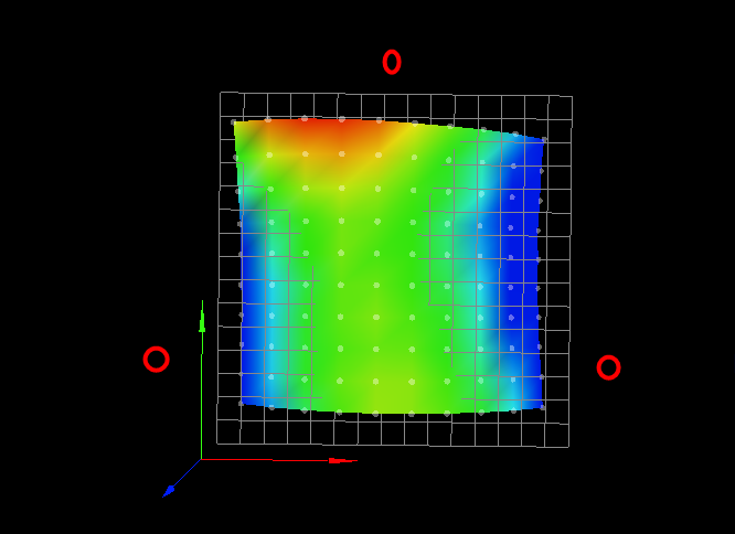
- My print bed absolutely sucks. It's horrible. "Flat" does not belog to its vocabulary. (over 0.5mm error)
- Bed leveling works as expected, consecutive runs minimize the error down to very small numbers and the probed heightmap confirms that it's as level as it's going to be.
- Mesh compensation itself "works" as well, I can see the Z steppers turning while the head moves. They also turn in the technically correct direction.
- My printer produces dimensionally accurate parts with tiny tolerances, so I feel like that area is covered
- I do auto bed leveling and mesh probing before every print as piece of my start gcode
- When microstepping during the first layer, I can technically make sure to have a perfect layer when I manually move the babystepping depending on where the head happens to be (a manual heightmap so to speak). This makes me thing that my Z-axis is capable of producing small enough movements for a good first layer.
Now for the actual issue and what I think could be the culprit:
The compensation does not work well at all, during one print, in some places it overcompensates just a little, in other places it undercompensates. These places are fixed, ie top left would be undercompensating while bottom right (for example) it would overcompensate and squish the filament too much.
Funnily enough, when the nozzle is too far from the bed, it's a pretty constant error, it's not really changing over long runs of perimeter.The frustrating thing is that this worked all super fine (with the very same Z-axis) before I converted it to a toolchanger. I tried all the normal things, re-lubed the axis, made sure nothing was binding, etc etc.
The only thing that stands out to me is that my 0,0 is NOT where my nozzle is. With the E3D toolchanger setup, 0,0 is the Z-Probe and every tool has a non-0 offset in both X and Y.
So this leads me to think that maybe the mesh compensation is using the wrong offset because it looks at relative 0,0 rather the actual nozzle for the heightmap value...Now, this would seem like a fairly obvious issue right? Maybe it's not so obvious if your bed isn't as horrible as mine...
For those interested what I mean when I say the bed is horrible:
100 points probed, min error -0.419, max error 0.273, mean -0.050, deviation 0.161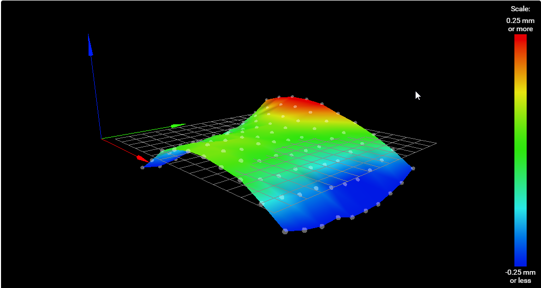
So maybe @dc42 can take a very eagle-eyed look at the code and reassure me that everything is fine there... Because this is driving me nuts.
I already ordered a new build-plate because I couldn't stand this anymore. My printer used to be maintenance free, fire and forget so to speak.
I probe before each print and I literally did not have to care at all, start the job and there was a 100% success rate with perfect first layers... These days the toolchanging is awesome, but the first layer really takes the fun away...The reason I am suspecting this specific behavior is another thread I just made.
DWC's gcode viewer plugin shows (at least seemingly) the exact behavior I am talking about:
https://forum.duet3d.com/topic/23816/g-code-viewer-wrong-cursor-positionIt's displaying the toolnozzle at the wrong place, if the heightmap lookup code does something similar it would create big issues for beds as bad as mine.
Here are some pictures of the effect:


Maybe someone can help me...
-
That saddle shape is more likely to be sag in the X axis rail rather than the bed itself. One way to check for sure would be to rotate your bed surface 90 degree and see if the saddle remains the same.
Is your printer an E3D tool changer, or something else?
What kind of probe? How is it mounted?
Can you please share your full config.g, homeall/homez, bed.g files?
Also the results of M122 and M98 P"config.g"?With that info we might have an idea of things to improve.
-
@phaedrux I wish it was that easy... I placed my new bed on top of the old one (the new is a milled 6mm aluminium tooling plate) and that one is almost perfectly flat.
So yea, the bed really is that bad (It's a known issue with that specific printer, many other users have very similar looking beds that get fixed when upgrading to the new 6mm one)The printer is a custom XY motionsystem with all of the original E3D toolchanging hardware (toolhead, tools) installed. This means the probe and its setup is exactly the same as the E3D one (simple microswitch)
M122
=== Diagnostics ===
RepRapFirmware for Duet 2 WiFi/Ethernet version 3.3 (2021-06-15 21:44:54) running on Duet WiFi 1.02 or later + DueX5
Board ID: 08DGM-917NK-F2MS4-7J9F2-3S86N-TYTWF
Used output buffers: 3 of 24 (24 max)
=== RTOS ===
Static ram: 23876
Dynamic ram: 80972 of which 204 recycled
Never used RAM 6508, free system stack 98 words
Tasks: NETWORK(ready,113.2%,227) ACCEL(notifyWait,0.0%,334) HEAT(delaying,0.5%,330) Move(notifyWait,1.5%,283) DUEX(notifyWait,0.0%,24) MAIN(running,110.5%,420) IDLE(ready,0.1%,29), total 225.8%
Owned mutexes: WiFi(NETWORK)
=== Platform ===
Last reset 08:38:49 ago, cause: software
Last software reset at 2021-06-20 23:42, reason: User, GCodes spinning, available RAM 6524, slot 2
Software reset code 0x0003 HFSR 0x00000000 CFSR 0x00000000 ICSR 0x0041f000 BFAR 0xe000ed38 SP 0x00000000 Task MAIN Freestk 0 n/a
Error status: 0x04
Aux0 errors 0,0,0
Step timer max interval 0
MCU temperature: min 31.8, current 32.3, max 42.2
Supply voltage: min 23.9, current 24.3, max 24.5, under voltage events: 0, over voltage events: 0, power good: yes
Heap OK, handles allocated/used 99/8, heap memory allocated/used/recyclable 2048/1486/1374, gc cycles 0
Driver 0: position 36960, standstill, SG min/max 0/1023
Driver 1: position 13920, standstill, SG min/max 0/1023
Driver 2: position 33880, standstill, SG min/max 0/525
Driver 3: position 24000, standstill, SG min/max 0/1023
Driver 4: position 0, standstill, SG min/max not available
Driver 5: position 0, standstill, SG min/max not available
Driver 6: position 0, standstill, SG min/max not available
Driver 7: position 0, standstill, SG min/max 0/1023
Driver 8: position 0, standstill, SG min/max 0/1023
Driver 9: position 0, standstill, SG min/max 0/1023
Driver 10: position 0
Driver 11: position 0
Date/time: 2021-06-21 08:21:42
Cache data hit count 4294967295
Slowest loop: 96.93ms; fastest: 0.10ms
I2C nak errors 0, send timeouts 0, receive timeouts 0, finishTimeouts 0, resets 0
=== Storage ===
Free file entries: 10
SD card 0 detected, interface speed: 20.0MBytes/sec
SD card longest read time 1.2ms, write time 7.7ms, max retries 0
=== Move ===
DMs created 83, maxWait 203017ms, bed compensation in use: mesh, comp offset 0.000
=== MainDDARing ===
Scheduled moves 107313, completed moves 107313, hiccups 0, stepErrors 0, LaErrors 0, Underruns [1, 0, 0], CDDA state -1
=== AuxDDARing ===
Scheduled moves 0, completed moves 0, hiccups 0, stepErrors 0, LaErrors 0, Underruns [0, 0, 0], CDDA state -1
=== Heat ===
Bed heaters = 0 -1 -1 -1, chamberHeaters = -1 -1 -1 -1
=== GCodes ===
Segments left: 0
Movement lock held by null
HTTP is idle in state(s) 0
Telnet is idle in state(s) 0
File is idle in state(s) 0
USB is idle in state(s) 0
Aux is idle in state(s) 0
Trigger is idle in state(s) 0
Queue is idle in state(s) 0
LCD is idle in state(s) 0
Daemon is idle in state(s) 0
Autopause is idle in state(s) 0
Code queue is empty.
=== DueX ===
Read count 7, 0.01 reads/min
=== Network ===
Slowest loop: 66.31ms; fastest: 0.00ms
Responder states: HTTP(0) HTTP(0) HTTP(0) HTTP(0) FTP(0) Telnet(0), 0 sessions
HTTP sessions: 1 of 8
- WiFi -
Network state is active
WiFi module is connected to access point
Failed messages: pending 0, notready 0, noresp 0
WiFi firmware version 1.26
WiFi MAC address b4:e6:2d:52:f2:a9
WiFi Vcc 3.42, reset reason Power up
WiFi flash size 4194304, free heap 26736
WiFi IP address 192.168.1.31
WiFi signal strength -62dBm, mode 802.11n, reconnections 0, sleep mode modem
Clock register 00002002
Socket states: 0 0 0 0 0 0 0 0
results from config.g
Warning: Heater 0 appears to be over-powered. If left on at full power, its temperature is predicted to reach 345C
Warning: Heater 1 appears to be over-powered. If left on at full power, its temperature is predicted to reach 641C
Warning: Heater 2 appears to be over-powered. If left on at full power, its temperature is predicted to reach 553C
Warning: Heater 3 appears to be over-powered. If left on at full power, its temperature is predicted to reach 577C
Warning: Heater 4 appears to be over-powered. If left on at full power, its temperature is predicted to reach 598C
Accelerometer 0 with orientation 20 samples at 1344Hz with 10-bit resolution
config.g (edit: no idea where the "{1}" in line 44 comes from, this is actually neither in config.g nor in the code pasted here... )
; Configuration file for Duet WiFi (firmware version 3)
; executed by the firmware on start-up
;
; generated by RepRapFirmware Configuration Tool v2.1.8 on Sun May 10 2020 15:03:19 GMT+0200 (Mitteleuropäische Sommerzeit)

; General preferences
;M929 S3                                        ;enable debug logging
M575 P1 S1 B57600                               ;Enable PanelDue Port
G90                                             ; send absolute coordinates...
M83                                             ; ...but relative extruder moves
M550 P"V-Core Pro"                              ; set printer name

M669 K1                                         ; select CoreXY mode

; Network
M552 S1                                         ; enable network

; Drives
M569 P0 S0                                      ; stepper X/Y
M569 P1 S0                                      ; stepper X/Y
M569 P2 S0                                      ; stepper Coupler
M569 P3 S0                                      ; stepper E1
M569 P4 S0                                      ; stepper E2
M569 P5 S0                                      ; stepper E3
M569 P6 S0                                      ; stepper E4
M569 P7 S0                                      ; stepper Z1
M569 P8 S0                                      ; stepper Z2
M569 P9 S0                                      ; stepper Z3

M584 X0 Y1 C2 Z7:8:9                            ; set drive mapping (motion system)
M584 E3:4:5:6                                   ; set drive mapping (extruders)

; Axis Limits
global minY = -149
global maxY = 72
M208 X-146:159 Y{global.minY}:{global.maxY} C0:250 Z0:290     ; set axis minima & maxima
M671 X-161:4:189 Y-118:177:-118 S20             ; set Z leadscrew positions

M92 X160.00 Y160.00 C200.00 Z800.00             ; set steps per mm
M350 X16 Y16 C16 Z16 I1                         ; configure microstepping with interpolation
M566 X500 Y500 C2 Z70                           ; set maximum instantaneous speed changes (mm/min)
M203 X30000 Y30000 C10000 Z2000                 ; set maximum speeds (mm/min)
M201 X2000 Y2000 C500 Z500                      ; set accelerations (mm/s^2)

M906 X1800 Y1800 C500 I30                       ; set motor currents (mA) and motor idle factor in per cent
M906 Z1400 I100                                 ; set motor currents (mA) and motor idle factor in per cent
M906 E600:600:600:600 I100                      ; set motor currents (mA) and motor idle factor in per cent (2x Flex3Drive 2x LGX)
M84 S30                                         ; Set idle timeout
;M204 P1500 T3000
;M593 F40  ; cancel ringing

;=================== Extruder ======================
M92 E408:408:408:408                            ; set steps per mm
M350 E16:16:16:16 I1                            ; configure microstepping
M566 E1200:1200:1200:1200                       ; set maximum instantaneous speed changes (mm/min)
M203 E4000:4000:4000:4000                       ; set maximum speeds (mm/min)
M201 E3000:3000:3000:3000                       ; set accelerations (mm/s^2)
;====================================================

; Endstops
M574 X2 S1 P"xstop"                             ; configure active-high endstop for high end on X via pin xstop
M574 Y1 S1 P"ystop"                             ; configure active-high endstop for high end on Y via pin ystop
M574 Z0                                         ; No Z-Endstop (use as probe instead)
M574 C1 S3                                      ; Stall detect coupler at low end of its range
;Stall Detection
M915 C S6 F0 H200 R0                            ; Coupler

; Z-Probe
M558 P8 C"zstop" H3 F1000 T20000                ; set Z probe type to unfiltered switch and the dive height + speeds
G31 X0 Y0 Z0 P200                               ; set Z probe trigger value, offset and trigger height
global minYMesh = global.minY
global maxYMesh = 115
M557 X-146:150 Y{global.minYMesh}:{global.maxYMesh} P10                     ; define mesh grid
M376 H30                                        ; Set bed correction taper

; Heaters
M308 S0 P"bedtemp" Y"thermistor" T100000 B3950  ; configure sensor 0 as thermistor on pin bedtemp
M950 H0 C"bedheat" T0                           ; create bed heater output on bedheat and map it to sensor 0
M143 H0 S121                                    ; set temperature limit for heater 0 to 121C
M307 H0 R0.712 C450.5 D4.85 S1.00 V24.3         ; Bed PID Tuning
M140 H0                                         ; map heated bed to heater 0

M308 S1 P"e0_temp" Y"thermistor" T100000 B4725 C7.06e-8  ; configure sensor 1 as thermistor on pin e0temp
M950 H1 C"e0heat" T1                            ; create nozzle heater output on e0heat and map it to sensor 1
M143 H1 S301                                    ; set temperature limit for heater 1 to 301C

M308 S2 P"e3_temp" Y"thermistor" T100000 B4725 C7.06e-8  ; configure sensor 2 as thermistor on pin e3temp
M950 H2 C"duex.e3heat" T2                            ; create nozzle heater output on e3heat and map it to sensor 2
M143 H2 S301                                    ; set temperature limit for heater 2 to 301C

M308 S3 P"e2_temp" Y"thermistor" T100000 B4725 C7.06e-8  ; configure sensor 3 as thermistor on pin e2temp
M950 H3 C"duex.e2heat" T3                            ; create nozzle heater output on e2heat and map it to sensor 3
M143 H3 S301                                    ; set temperature limit for heater 3 to 301C

M308 S4 P"e1_temp" Y"thermistor" T100000 B4725 C7.06e-8  ; configure sensor 4 as thermistor on pin e1temp
M950 H4 C"e1heat" T4                            ; create nozzle heater output on e1heat and map it to sensor 4
M143 H4 S301                                    ; set temperature limit for heater 4 to 301C


M302 S190 R190                                  ;Cold extrusion settings

M307 H1 B0 R4.292 C143.6:138.0 D3.25 S1.00 V24.2 ; PID Tuning T0
M307 H2 B0 R3.836 C137.7:128.8 D1.66 S1.00 V24.2 ; PID Tuning T1
M307 H3 B0 R3.967 C139.3:126.4 D1.79 S1.00 V24.2 ; PID Tuning T1
M307 H4 B0 R3.965 C144.7:139.8 D1.96 S1.00 V24.2 ; PID Tuning T1

; Fans
M950 F0 C"duex.fan3"                            ; Hotend Fan Tool 0
M106 P0 S255 L255 H1 T50                        ; Hotend Fan Tool 0
M950 F1 C"duex.fan4" Q50                        ; Layer Fan Tool 0
M106 P1 S0 H-1                                  ; Layer Fan Tool 0

M950 F2 C"fan0"                                 ; Hotend Fan Tool 1
M106 P2 S255 L255 H2 T50                        ; Hotend Fan Tool 1
M950 F3 C"fan2" Q50                             ; Layer Fan Tool 1
M106 P3 S0 H-1                                  ; Layer Fan Tool 1

M950 F4 C"duex.fan7"                            ; Hotend Fan Tool 2
M106 P4 S255 L255 H3 T50                        ; Hotend Fan Tool 2
M950 F5 C"duex.fan8" Q50                        ; Layer Fan Tool 2
M106 P5 S0 H-1                                  ; Layer Fan Tool 2

M950 F6 C"duex.fan5"                            ; Hotend Fan Tool 3
M106 P6 S255 L255 H4 T50                        ; Hotend Fan Tool 3
M950 F7 C"duex.fan6" Q50                        ; Layer Fan Tool 3
M106 P7 S0 H-1                                  ; Layer Fan Tool 3

;Z-Offset: 	If nozzle is too close to bed _reduce_ offset (negative number becomes more negative)
;			If nozzle is too far away, _increase_ offset (negative number becomes less negative)
; Tools
M563 P0 D0 H1 F1                                ; define tool 0
G10 P0 X-9 Y39 Z-4.70                           ; set tool 0 axis offsets
G10 P0 R0 S0                                    ; set initial tool 0 active and standby temperatures to 0C

M563 P1 D3 H2 F3                                ; define tool 1
G10 P1 X-9.40 Y39.05 Z-5.04                      ; set tool 1 axis offsets
G10 P1 R0 S0                                    ; set initial tool 1 active and standby temperatures to 0C

M563 P2 D2 H3 F5                                ; define tool 2
G10 P2 X-9.15 Y39.1 Z-4.91                      ; set tool 2 axis offsets
G10 P2 R0 S0                                    ; set initial tool 2 active and standby temperatures to 0C

M563 P3 D1 H4 F7                                ; define tool 3
G10 P3 X-9.35 Y38.4 Z-5.07                      ; set tool 3 axis offsets
G10 P3 R0 S0                                    ; set initial tool 3 active and standby temperatures to 0C

;Dock present switches
M950 J0 C"duex.e2stop"                          ; Tool 0 Dock switch
M950 J1 C"duex.e5stop"                          ; Tool 1 Dock switch
M950 J2 C"duex.e4stop"                          ; Tool 2 Dock switch
M950 J3 C"duex.e3stop"                          ; Tool 3 Dock switch

M950 S0 C"duex.pwm5"                          ;PebbleWiper Servo
M950 P1 C"duex.pwm4"                          ;Light switch PWM
;M591 D0 P1 C"e0stop" S1                        ;Filament Sensor E0

;Accelerometer
M955 P0 C"spi.cs3+spi.cs4"
;M593 F78
homeall.g
; homeall.g
; called to home all axes

M98 P"homey.g"			; Home Y first, so that a head that is currently in one of the tool docks homes correctly
M98 P"homex.g"			; Home X

;check if any tool is undocked
if sensors.gpIn[0].value = 0 || sensors.gpIn[1].value = 0 || sensors.gpIn[2].value = 0 || sensors.gpIn[3].value = 0
	echo "Not all tools docked, docking tool before homing!"
	M98 P"/macros/Toolchanging/DockUnknownToolEmergency"

M98 P"homec.g"			; Home C (ToolHead)
M98 P"homez.g"			; Home Z
homez.g
; homez.g
; called to home the Z axis
;
; generated by RepRapFirmware Configuration Tool v2 on Thu Dec 13 2018 18:14:06 GMT+0100 (Central European Standard Time)

if sensors.gpIn[0].value = 0 || sensors.gpIn[1].value = 0 || sensors.gpIn[2].value = 0 || sensors.gpIn[3].value = 0
	M291 S1 T5 P"Please return tool to dock before homing Z" R"Can't home Z"
	abort


G90               ; absolute positioning
G1 X0 Y0 F15000 ; go to first probe point
G30               ; home Z by probing the bed
G91               ; relative positioning
G1 Z10 F1000
bed.g
M98 P"/macros/Bed/Level"
M208 Y{global.minY}:{global.maxYMesh} ; extend allowed space for probing near the edge of the bed
G29 S0
G1 X400 Y{global.maxY} F20000		          ; Park
M208 Y{global.minY}:{global.maxY}     ;reset safe moving space to normal
/macros/Bed/Level
M564 S1 M561 ; clear any bed transform if !move.axes[0].homed || !move.axes[1].homed || !move.axes[2].homed G28 T-1 while true G30 P1 X-30 Y-147 Z-99999 ; probe leadscrew 1 G30 P0 X30 Y-147 Z-99999 ; probe leadscrew 2 G30 P2 X0 Y72 Z-99999 S3; probe leadscrew 3 if move.calibration.initial.deviation <= 0.01 echo "Leveling successful. Deviation: " ^ move.calibration.initial.deviation ^ "mm" break if iterations >= 10 break echo "Repeating leveling because deviation is too high (" ^ move.calibration.initial.deviation ^ "mm)" G28 Z -
I have the very same problem! And I also have a toolchanger just like you, custom CoreXY motion system with e3d toolchanger hardware. The thing is my bed is almost flat and it doesn't make my prints fail, but I no longer have the perfect first layers I used to have since I went toolchanging. I even thought that the extra weight of the tool was making my X gantry sag, but the expected sagging doesn't quite match the effect I see when printing.
-
Hi.
In your bed leveling macro your three X positions (-30, 30, 0) are very close to bed center rather then being out near the leadscrews.
Are those value correct?
Thanks.
Frederick
-
@fcwilt Not sure if that specific bed level pattern has any negative effects that I am not aware of, but yes, it's correct as far as I can tell.
It was deliberately chosen that way so that I do the probes in the flat-ish area in the middle of the bed, if I probe near the leadscrews (which I've tried before) the final bed "level" is all weird due to it trying to work its best with that pringle shaped bed. (the whole bed ends up at an angle then)Here is where the leadscrews are (roughly). If I were to probe near the screws, it would take those three points for its plane fitting, two of those are super low and one is super high, leading to an overall tilt of the bed plane.
The bed level process itself works fine to the best of my knowledge, even extreme tilts are corrected properly and within usually 2-4 leveling passes, the reported deviation is below 0.01mm.
-
@diamondback I've got a similar printer shape on my bed which is mostly down to sag and twist in the x gantry (I have a heavy print head with some offset from the rail).
With the toolchanger you probe without a tool mounted, so there's the extra mass to cause sag, and the mass is off to one side which can also twist the rail a bit. Have you tried loading a dummy tool to get the probing weight closer to the printing weight?
This is as much a question than an answer as I'm thinking of converting mine to a toolchanger! -
@engikeneer I was thinking about an effect like that as well, but wouldn't the Z-Offset caused by this be constant? Or at least purely dependant on the X position? (assuming that there is less sag near the min/max extends of X)
And no, don't have any dummy weight. Note though, I have fairly heavy tools (Bondtech LGX on the tool itself), as well as fairly light ones (remote direct extruder) and they don't show any difference in behavior.
-
@Diamondback
I'm no config wizard, so I can only share my impression about the whole Z-probe offset.
I read through all the related wiki pages and got more and more confused about the 'sign' of the offsets (positive or negative?)Your description of the DWC output seems to indicate, you've set them wrong.
That doesn't explain why it worked pre-toolchanger, but maybe back then your nozzle was 0,0 not the probe? -
@o_lampe Pre-Toolchanger it was a normal CoreXY, so Nozzle at 0,0 and probe at some offset.
Any idea what other symptoms a wrong offset sign would cause? Or how to actually check?
As far as I can tell, things work as expected apart from the mesh compensation. -
-
@diamondback said in Bed mesh correction and tool offsets...:
Or how to actually check?
Move to a specific point (center of bed) before a tool is applied. The probe would point to that spot.
Then load a tool and move to that spot again. Does the nozzle point to that spot? -
@diamondback do you have a substantial X offset between the probe and the nozzle? If so, and if the problem is that the X gantry is sagging as @Phaedrux suggests (which seems likely to me) then there are two effects which will cause height errors:
-
The bed compensation algorithm assumes that the printer XY movement occurs in a flat plane but the bed isn't flat. Therefore it adjusts the height according to where the nozzle is, not where the probe is. If the primary cause of height errors is a sagging X gantry then that won't work well, and it would be better to set the probe X offset to zero (and then check that it doesn't cause the machine to try to probe off the edge of the bed).
-
The X offset of the probe will also cause the relative height of the probe and nozzle to vary with X position. This is because the X carriage is tilting one way at one end of the X axis, and the other way at the other end. That will lead to the height map causing the nozzle to be too high at one end of the X axis and too low at the other.
Whatever the cause of that height map, you need to address it. If it's sag in the X gantry, you need a more rigid gantry. Are you using the original gantry with much heavier tools and pickup assembly than your original print head?
Duet WiFi hardware designer and firmware engineer
Please do not ask me for Duet support via PM or email, use the forum
http://www.escher3d.com, https://miscsolutions.wordpress.com -
-
@dc42 The probe/nozzle offsets are the same as regular E3D V6 tools. Weight wise, think roughly Hemera tool.
As noted above, the bed itself is definitely the main source of the funky height map, my new bed is much better (tested by literally placing the new bed plate on top of the existing bed and probing that), but it will be a while until I can actually use that.I'm not sure I understand point 2), why would the X carriage tilt in different directions depending on whether it's at X min or X max?
I recognize that there certainly is some softness in my X gantry ( I can deflect it by hand if I really want to...), but I don't understand how that would create the issues I am seeing.
The way Isee it, a loaded tool would rotate the toolhead around the X-gantry, possibly the most the in the middle and the least at the min/max (depending on where the primary softness comes from, the rail, the mounting to the Y rails, the X extrusion itself, etc)
But this would be a pretty symetrical issue, no?The motionsystem is not from E3D, only the toolchange hardware is, so it's definitely not as stiff as the E3D stuff.
-
@diamondback said in Bed mesh correction and tool offsets...:
@dc42 The probe/nozzle offsets are the same as regular E3D V6 tools. Weight wise, think roughly Hemera tool.
As noted above, the bed itself is definitely the main source of the funky height map, my new bed is much better (tested by literally placing the new bed plate on top of the existing bed and probing that), but it will be a while until I can actually use that.OK, then sorting out the bed should sort out most of the issue.
I'm not sure I understand point 2), why would the X carriage tilt in different directions depending on whether it's at X min or X max?
Think of a sagging X gantry like a chain hanging between two supports. Then a carriage hung fnr the chain by 2 wheels will tilt in one direction when it is near one end of the chain, and in the opposite direction when it is near the other end.
The way Isee it, a loaded tool would rotate the toolhead around the X-gantry, possibly the most the in the middle and the least at the min/max (depending on where the primary softness comes from, the rail, the mounting to the Y rails, the X extrusion itself, etc)
Yes I see a torsional oscillation around the X gantry on my E3D TC with the accelerometer.
Duet WiFi hardware designer and firmware engineer
Please do not ask me for Duet support via PM or email, use the forum
http://www.escher3d.com, https://miscsolutions.wordpress.com -
@dc42 Oh, you were talking about another tilt axis with the chain thing, yea, that makes sense. I will re-probe my new bed (just on top of the old) so you get an idea of how bad the current bed really is.
-
@dc42 Here's the "new" bed, I just slapped it on top of the existing bed, so likely this is not the best it will be eventually. The Z motion system will also be replace to be a kinematic coupling style so the bed can extend properly when heating.
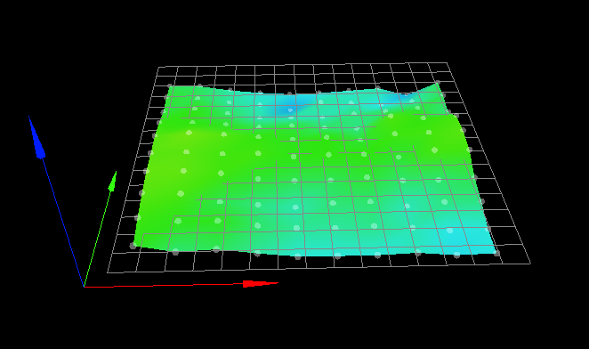
I think it's safe to assume that the saddle shape does not arise from sag in the gantry, but rather from the bed itself.
I would really like to get this fixed though. It will easily take another month or so before I can actually use the new bed (missing hardware, printed parts that need actual printing etc)
-
If the adjustments to the z position with baby stepping are consistent based on XY location as you say, then you could potentially directly edit the heightmap.csv to alter the points to match reality.
-
@phaedrux Yea I guess technically that would be possible, but I have really no idea how one would do that in practice (finding the offset for each recorded csv value during a print).
I guess maybe one would have to print a grid or something very slowly and a turn at each probe point so it applies the new babystepping?Dunno, seems... complicated

-
@diamondback said in Bed mesh correction and tool offsets...:
Dunno, seems... complicated
Because it is.
Perhaps the best meaningful solution is to simply wait until you can replace the current bed with something better.
Frederick