Bed mesh correction and tool offsets...
-
@diamondback I've got a similar printer shape on my bed which is mostly down to sag and twist in the x gantry (I have a heavy print head with some offset from the rail).
With the toolchanger you probe without a tool mounted, so there's the extra mass to cause sag, and the mass is off to one side which can also twist the rail a bit. Have you tried loading a dummy tool to get the probing weight closer to the printing weight?
This is as much a question than an answer as I'm thinking of converting mine to a toolchanger! -
@engikeneer I was thinking about an effect like that as well, but wouldn't the Z-Offset caused by this be constant? Or at least purely dependant on the X position? (assuming that there is less sag near the min/max extends of X)
And no, don't have any dummy weight. Note though, I have fairly heavy tools (Bondtech LGX on the tool itself), as well as fairly light ones (remote direct extruder) and they don't show any difference in behavior.
-
@Diamondback
I'm no config wizard, so I can only share my impression about the whole Z-probe offset.
I read through all the related wiki pages and got more and more confused about the 'sign' of the offsets (positive or negative?)Your description of the DWC output seems to indicate, you've set them wrong.
That doesn't explain why it worked pre-toolchanger, but maybe back then your nozzle was 0,0 not the probe? -
@o_lampe Pre-Toolchanger it was a normal CoreXY, so Nozzle at 0,0 and probe at some offset.
Any idea what other symptoms a wrong offset sign would cause? Or how to actually check?
As far as I can tell, things work as expected apart from the mesh compensation. -
-
@diamondback said in Bed mesh correction and tool offsets...:
Or how to actually check?
Move to a specific point (center of bed) before a tool is applied. The probe would point to that spot.
Then load a tool and move to that spot again. Does the nozzle point to that spot? -
@diamondback do you have a substantial X offset between the probe and the nozzle? If so, and if the problem is that the X gantry is sagging as @Phaedrux suggests (which seems likely to me) then there are two effects which will cause height errors:
-
The bed compensation algorithm assumes that the printer XY movement occurs in a flat plane but the bed isn't flat. Therefore it adjusts the height according to where the nozzle is, not where the probe is. If the primary cause of height errors is a sagging X gantry then that won't work well, and it would be better to set the probe X offset to zero (and then check that it doesn't cause the machine to try to probe off the edge of the bed).
-
The X offset of the probe will also cause the relative height of the probe and nozzle to vary with X position. This is because the X carriage is tilting one way at one end of the X axis, and the other way at the other end. That will lead to the height map causing the nozzle to be too high at one end of the X axis and too low at the other.
Whatever the cause of that height map, you need to address it. If it's sag in the X gantry, you need a more rigid gantry. Are you using the original gantry with much heavier tools and pickup assembly than your original print head?
Duet WiFi hardware designer and firmware engineer
Please do not ask me for Duet support via PM or email, use the forum
http://www.escher3d.com, https://miscsolutions.wordpress.com -
-
@dc42 The probe/nozzle offsets are the same as regular E3D V6 tools. Weight wise, think roughly Hemera tool.
As noted above, the bed itself is definitely the main source of the funky height map, my new bed is much better (tested by literally placing the new bed plate on top of the existing bed and probing that), but it will be a while until I can actually use that.I'm not sure I understand point 2), why would the X carriage tilt in different directions depending on whether it's at X min or X max?
I recognize that there certainly is some softness in my X gantry ( I can deflect it by hand if I really want to...), but I don't understand how that would create the issues I am seeing.
The way Isee it, a loaded tool would rotate the toolhead around the X-gantry, possibly the most the in the middle and the least at the min/max (depending on where the primary softness comes from, the rail, the mounting to the Y rails, the X extrusion itself, etc)
But this would be a pretty symetrical issue, no?The motionsystem is not from E3D, only the toolchange hardware is, so it's definitely not as stiff as the E3D stuff.
-
@diamondback said in Bed mesh correction and tool offsets...:
@dc42 The probe/nozzle offsets are the same as regular E3D V6 tools. Weight wise, think roughly Hemera tool.
As noted above, the bed itself is definitely the main source of the funky height map, my new bed is much better (tested by literally placing the new bed plate on top of the existing bed and probing that), but it will be a while until I can actually use that.OK, then sorting out the bed should sort out most of the issue.
I'm not sure I understand point 2), why would the X carriage tilt in different directions depending on whether it's at X min or X max?
Think of a sagging X gantry like a chain hanging between two supports. Then a carriage hung fnr the chain by 2 wheels will tilt in one direction when it is near one end of the chain, and in the opposite direction when it is near the other end.
The way Isee it, a loaded tool would rotate the toolhead around the X-gantry, possibly the most the in the middle and the least at the min/max (depending on where the primary softness comes from, the rail, the mounting to the Y rails, the X extrusion itself, etc)
Yes I see a torsional oscillation around the X gantry on my E3D TC with the accelerometer.
Duet WiFi hardware designer and firmware engineer
Please do not ask me for Duet support via PM or email, use the forum
http://www.escher3d.com, https://miscsolutions.wordpress.com -
@dc42 Oh, you were talking about another tilt axis with the chain thing, yea, that makes sense. I will re-probe my new bed (just on top of the old) so you get an idea of how bad the current bed really is.
-
@dc42 Here's the "new" bed, I just slapped it on top of the existing bed, so likely this is not the best it will be eventually. The Z motion system will also be replace to be a kinematic coupling style so the bed can extend properly when heating.
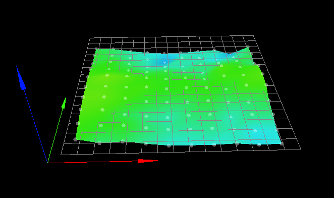
I think it's safe to assume that the saddle shape does not arise from sag in the gantry, but rather from the bed itself.
I would really like to get this fixed though. It will easily take another month or so before I can actually use the new bed (missing hardware, printed parts that need actual printing etc)
-
If the adjustments to the z position with baby stepping are consistent based on XY location as you say, then you could potentially directly edit the heightmap.csv to alter the points to match reality.
-
@phaedrux Yea I guess technically that would be possible, but I have really no idea how one would do that in practice (finding the offset for each recorded csv value during a print).
I guess maybe one would have to print a grid or something very slowly and a turn at each probe point so it applies the new babystepping?Dunno, seems... complicated

-
@diamondback said in Bed mesh correction and tool offsets...:
Dunno, seems... complicated
Because it is.
Perhaps the best meaningful solution is to simply wait until you can replace the current bed with something better.
Frederick
-
@fcwilt Hm... While an option, I don't feel this is the correct option here...
This bed worked fine, so it's not like RRF can't deal with it. I really feel like some place is using the wrong tool offsets... -
@diamondback said in Bed mesh correction and tool offsets...:
M208 X-146:159 Y{global.minY}:{global.maxY} C0:250 Z0:290 ; set axis minima & maxima
Can you check that anywhere you have variables and conditional code that it evaluated correctly?
You can send M208 M577 etc by themselves in the gcode console and it will report what the current value is.
-
@phaedrux Will do, however, these globals are a super recent addition and the issue way predates this specific mesh setup.
-
@diamondback said in Bed mesh correction and tool offsets...:
@fcwilt Hm... While an option, I don't feel this is the correct option here...
This bed worked fine, so it's not like RRF can't deal with it. I really feel like some place is using the wrong tool offsets...Do you really want to print on a Pringle?
")
Frederick
-
So, the saga continues. I managed to upgrade my bed to the new version, adjusted the frame and linear rails a bit and finally ended up with this mesh when probing the raw bed surface (no print surface attached yet)
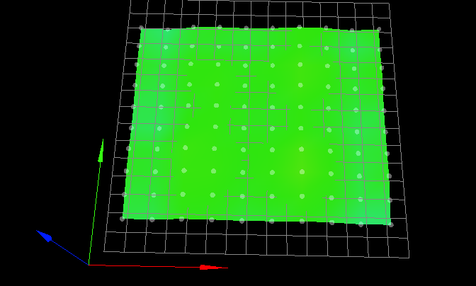
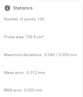
So, as far as I am concerned, this is as flat as it's ever going to be.
After installing the magnetic build surface I ended up with this as my final mesh:
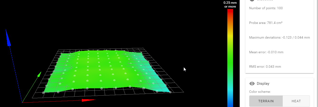
So while a little less perfect, still good enough.
The fun thing now is that the behavior still exists... So it wasn't the bed afterall.
Here you can see a random brim from some print. As you can see the top right corner still has a massively different Z-Offset than the rest...

This was printed right in the center of the bed, so where the mesh is perfectly flat.Any further ideas....?
-
I am in the very same situation. Same kind of machine, but just one Z motor moving two ballscrews.