Verifying mesh levelling
-
@fcwilt said in Verifying mesh levelling:
I don't actually understand what you are asking.
There is an offset between the probe and the nozzle. Assuming our offsets are correct, how can we verify that the mesh compensation take this offset correctly into account when applying the mesh compensation? Basically the probe mesh is offset in two directions to the primary nozzle.
If it takes the offset correctly into account then I would expect the nozzle to follow the mesh contour almost perfectly (given whatever extrapolation method it uses). However if it does not take the offset into account correctly or at all then the applied mesh would be offset from the nozzle and the nozzle would follow an offset contour.
We have a test spiral that covers the bed twice and he pair of lines is 25mm away from the other pair of lines. We see some spots that are nice and some a bit tight and squished, and others that do not adhere and were not proper layer thickness. This leans me to think the whole mesh is offset.
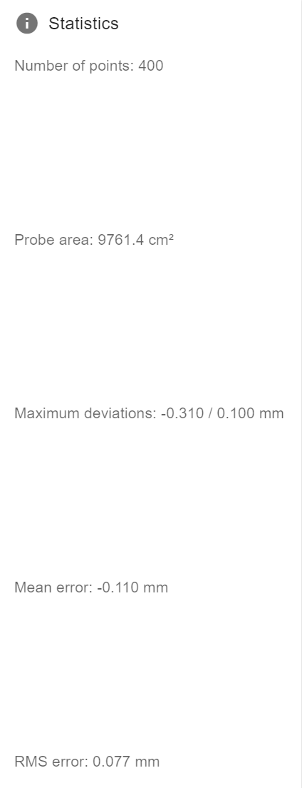
If we compare side by side points (given the large bed that is not easy to level manually) we see between 0.1 and 0.16mm difference in mesh pint heights. If this translates to the nozzle contour that would be great, but It does not. The first pair of points is beside a seam in the plates (three bead plates with 3 separate pieces of PEI. The second pair of points is along one plate.
As I said, I am questioning if the probe to nozzle offsets are correctly applied when the bed mesh is applied and questioning how to check that.
-
I've always assumed they are but it's easy to check.
Here is the text of a height map for testing:
RepRapFirmware height map file v2 generated at 2021-01-01 00:00, min error 0.000, max error 0.00, mean 0.000, deviation 0.000
xmin,xmax,ymin,ymax,radius,xspacing,yspacing,xnum,ynum
0.00,150.00,0.00,150.00,-1.00,15.00,150.00,11,2
0, 1, 2, 3, 4, 5, 6, 7, 8, 9, 10
0, 1, 2, 3, 4, 5, 6, 7, 8, 9, 10It greatly exaggerates Z errors so you can jog along the X axis and verify the Z adjustments.
Adjust these values as needed to match your printer:
xmin, xmax, ymin, ymax, radius, xspacing, yspacing, xnum, ynum
Create a file heightmap.csv in your system folder with the data above adjusted for your printer.
Enable mesh compensation using this file.
Frederick
-
@fcwilt said in Verifying mesh levelling:
That makes sense but I could not find where that is stated.
I think it's just convention, since you can set whatever you want as the origin and offset anything from anywhere if you want. It really depends on the setup what makes the most sense.
@fcwilt said in Verifying mesh levelling:
1X and Y offsets of the Z probe relative to the print head (i.e. the position when the empty tool is selected) can be specified. This allows you to calculate your probe coordinates based on the geometry of the bed, without having to correct them for Z probe X and Y offset.
but I don't know what it is trying to say.I think it might be talking about tool changer situations where you may have a probe attached to the head itself rather than a tool. I think the E3D tool changer is an example of that. There is a switch on the carriage itself that is used to probe. The tools are all offset from that.
-
@bstump said in Verifying mesh levelling:
If it takes the offset correctly into account then I would expect the nozzle to follow the mesh contour almost perfectly
Yes of course it takes the offset into account. It will adjust for your nozzle not the probe itself. That's why you tell it how far your probe is from the nozzle tip in XYZ.
-
@phaedrux said in Verifying mesh levelling:
@bstump said in Verifying mesh levelling:
If it takes the offset correctly into account then I would expect the nozzle to follow the mesh contour almost perfectly
Yes of course it takes the offset into account. It will adjust for your nozzle not the probe itself. That's why you tell it how far your probe is from the nozzle tip in XYZ.
If it does properly take it into account then we have bigger issues. If it does not take it into account then That would tend to look somewhat like the issues we are seeing.
We did find turning off taper did improve the first layer but not as much as hoped.
-
I thought of a way to prove the nozzle to probe offset is being taken into account correctly.
-
For the first point in the bed tilt probing, mark the bed with a sharpie at the expected probe spot +/-5mm. Likely all 4 corners.
-
Run the tilt macro and see if the probe comes down on the marked spots.
-
Now via the console, send the nozzle to those coordinates and also see if they match up.
-
I suppose I could generate a quick code to print a few loops of a circle at each spot. The sharpie dots should be centered on each circle.
If they all match up then we have some other issues, and we need to figure iut what the issue(s) is(are)
If they do not match up then the probe offset is not being compensated for correctly, and we need to figure out why.
This would not prove the mesh compensation compensates correctly for the probe to nozzle offset, but it is a first step in trusting that it does.
-
-
-
We did my little check and found that the probe offset is compensated for. We also did do some test prints where we turned off Taper and adhesion improved notably. So the questions now are
- Why does the taper adjustment degrade adhesion?
- What is happening in the algorithm that does the taper adjustment that it is not applying a consistent first layer thickness?
** Over 10mm taper ajdustment zone, the per layer adjustment should be ~2% of the needed mesh compensation.
** A pretty small number that should not impact bed adhesion.
Could it be at a mesh point ever 50mm is not enough to properly mesh the bed? Should we try a 900 point mesh vs the 400 point mesh we typically do?
-
@bstump the most mesh points you can have are 441
Owns various duet boards and is the main wiki maintainer for the Teamgloomy LPC/STM32 port of RRF. Assume I'm running whatever the latest beta/stable build is
-
@bstump said in Verifying mesh levelling:
Could it be at a mesh point ever 50mm is not enough to properly mesh the bed?
this is why I suggested doing a mesh of a smaller area of your printer where you will print a part and see if there is improvement.
@bstump said in Verifying mesh levelling:
Why does the taper adjustment degrade adhesion?
It's adsjusting the position less each layer than the measured amount over the distance set for the taper. If you use 10mm, at 5mm height it will have 50% less compensation effect such that by 10mm there is no compensation at all. If you set the taper too low, it will be reducing the compensation too much for what you need.
-
this is why I suggested doing a mesh of a smaller area of your printer where you will print a part and see if there is improvement.
We can try this on the worst area of the bed.
It's adjusting the position less each layer than the measured amount over the distance set for the taper. If you use 10mm, at 5mm height it will have 50% less compensation effect such that by 10mm there is no compensation at all. If you set the taper too low, it will be reducing the compensation too much for what you need.
I can understand at height this being the case, but the very first layer is different with the Taper on vs with the Taper off. I would not expect anything noticeable in the way of a difference between Taper on and Off for the first layer. But there is.
-
@jay_s_uk said in Verifying mesh levelling:
@bstump the most mesh points you can have are 441
Where is this documented? But this is reasonable.
-
-
@jay_s_uk Thanks
-
@bstump said in Verifying mesh levelling:
this is why I suggested doing a mesh of a smaller area of your printer where you will print a part and see if there is improvement.
We can try this on the worst area of the bed.
It's adjusting the position less each layer than the measured amount over the distance set for the taper. If you use 10mm, at 5mm height it will have 50% less compensation effect such that by 10mm there is no compensation at all. If you set the taper too low, it will be reducing the compensation too much for what you need.
I can understand at height this being the case, but the very first layer is different with the Taper on vs with the Taper off. I would not expect anything noticeable in the way of a difference between Taper on and Off for the first layer. But there is.
What did you have taper set to? There's only so many layers to apply the taper, the first layer isn't immune. Sounds like you might need a much larger taper height.
-
@phaedrux 10mm or about 2% per layer adjustment. at a 0.2mm layer height nor bed level variation, that ain't much.
-
@bstump said in Verifying mesh levelling:
that ain't much.
But apparently enough to make a difference.
-
@phaedrux said in Verifying mesh levelling:
@bstump said in Verifying mesh levelling:
that ain't much.
But apparently enough to make a difference.
So what taper do you suggest related to the med level deviation?
-
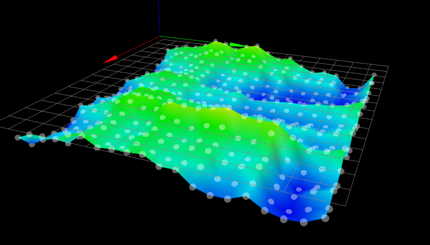
@bstump Post an image of your current heightmap with the values shown.
-
@phaedrux said in Verifying mesh levelling:
@bstump Post an image of your current heightmap with the values shown.