Verifying mesh levelling
-
this is why I suggested doing a mesh of a smaller area of your printer where you will print a part and see if there is improvement.
We can try this on the worst area of the bed.
It's adjusting the position less each layer than the measured amount over the distance set for the taper. If you use 10mm, at 5mm height it will have 50% less compensation effect such that by 10mm there is no compensation at all. If you set the taper too low, it will be reducing the compensation too much for what you need.
I can understand at height this being the case, but the very first layer is different with the Taper on vs with the Taper off. I would not expect anything noticeable in the way of a difference between Taper on and Off for the first layer. But there is.
-
@jay_s_uk said in Verifying mesh levelling:
@bstump the most mesh points you can have are 441
Where is this documented? But this is reasonable.
-
-
@jay_s_uk Thanks
-
@bstump said in Verifying mesh levelling:
this is why I suggested doing a mesh of a smaller area of your printer where you will print a part and see if there is improvement.
We can try this on the worst area of the bed.
It's adjusting the position less each layer than the measured amount over the distance set for the taper. If you use 10mm, at 5mm height it will have 50% less compensation effect such that by 10mm there is no compensation at all. If you set the taper too low, it will be reducing the compensation too much for what you need.
I can understand at height this being the case, but the very first layer is different with the Taper on vs with the Taper off. I would not expect anything noticeable in the way of a difference between Taper on and Off for the first layer. But there is.
What did you have taper set to? There's only so many layers to apply the taper, the first layer isn't immune. Sounds like you might need a much larger taper height.
-
@phaedrux 10mm or about 2% per layer adjustment. at a 0.2mm layer height nor bed level variation, that ain't much.
-
@bstump said in Verifying mesh levelling:
that ain't much.
But apparently enough to make a difference.
-
@phaedrux said in Verifying mesh levelling:
@bstump said in Verifying mesh levelling:
that ain't much.
But apparently enough to make a difference.
So what taper do you suggest related to the med level deviation?
-
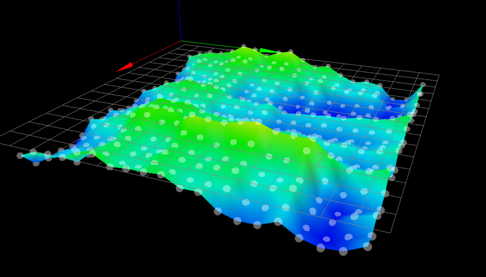
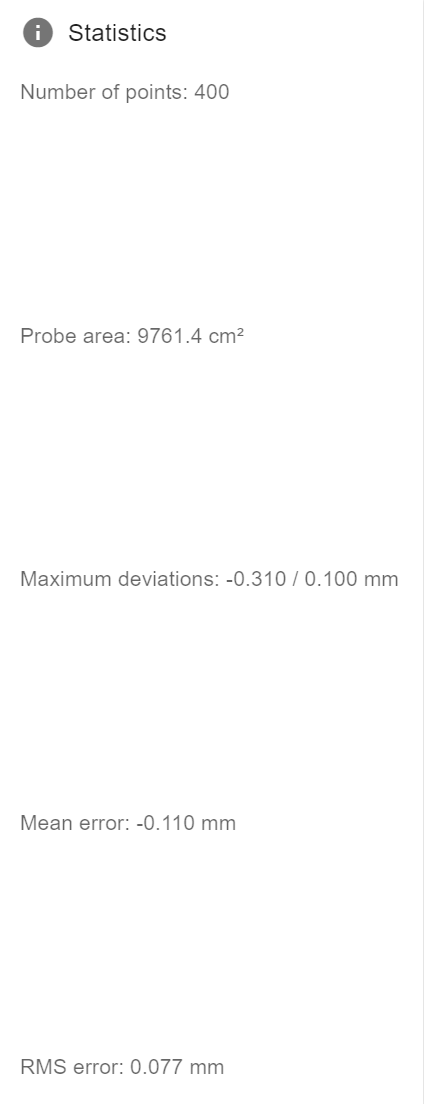
@bstump Post an image of your current heightmap with the values shown.
-
@phaedrux said in Verifying mesh levelling:
@bstump Post an image of your current heightmap with the values shown.
-
That center panel looks low given when this was generated. I am not sure the bed was fully heated or if the ceter was heated sufficiently.
-
With a bed like that I'd probably leave taper off entirely unless you're more concerned about wear and tear on the z axis. Otherwise try 50mm
Take a look at this to see if it might fit into your work flow.
https://forum.duet3d.com/topic/15302/cura-script-to-automatically-probe-only-printed-area
This way you could maximize the 440 points into the exact area you're printing on, with the downside of needing to probe before each print. Though if the area is smaller you could probably get away with fewer than the full 441.
Can you also post your config.g again? I can't seem to find it scrolling up. There are potentially improvements we can make to the probing settings.
-
@phaedrux said in Verifying mesh levelling:
@bstump Post an image of your current heightmap with the values shown.
I am wondering if the taper has some limits built in for how much or how little it can handle. Maybe given the overall bed size the variation is too much to deal with with one are it is apply a 0.00001mm taper adjustment and at another it needs a 0.01 per layer.
-
-
@fcwilt said in Verifying mesh levelling:
I don't use taper at all.
Frederick
We do jigs and fixtures and prototypes with this. Or that is the intention. given the flatness of the best not using taper could be an issue. But so is not adhering.
-
I use cast tool plate for the beds of my printers which from my supplier is spec'd to be flat within 0.4 mm but is usually much better.
I have found that bed adhesion is affected by many factors but these are what work for me:
- use the best cast tool plate you can find
- get the bed level within 0.005mm
- use 400 point mesh compensation
- use a first layer printing speed 10%-20% of the normal print speed
- turn off the part cooling fan for the first layer
Frederick
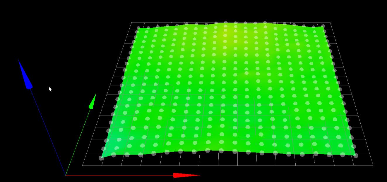
Here is the height map from my modified FT5 printer:
Printers: a E3D MS/TC setup and a RatRig Hybrid. Using Duet 3 hardware running 3.4.6
-
@fcwilt said in Verifying mesh levelling:
use the best cast tool plate you can find
1 square meter of cast tooling plate may be a bit expensive.
-
@phaedrux said in Verifying mesh levelling:
@fcwilt said in Verifying mesh levelling:
use the best cast tool plate you can find
1 square meter of cast tooling plate may be a bit expensive.
Very - but I don't see much point in building such a printer if it cannot be used to print things.
My goto vendor would want appx:
- $260 for 3000mm by 3000mm by 6mm
- $270 for 3000mm by 3000mm by 12mm
- $470 for 3000mm by 3000mm by 24mm
I find it interesting that 12mm is close in price to 6mm.
Frederick
-
@fcwilt said in Verifying mesh levelling:
I use cast tool plate for the beds of my printers which from my supplier is spec'd to be flat within 0.4 mm but is usually much better.
I have found that bed adhesion is affected by many factors but these are what work for me:
- use the best cast tool plate you can find
- get the bed level within 0.005mm
- use 400 point mesh compensation
- use a first layer printing speed 10%-20% of the normal print speed
- turn off the part cooling fan for the first layer
Frederick
Here is the height map from my modified FT5 printer:
Always 400 point mesh.
The first layer speed is typically ~50% of the other layer speed.
We have 0% fans for the first 10 layers to improve bed adhesion and reduce warping.
Our bed is made from three rectangular Aluminum plate. And on that are three PEI sheets. The overall bed if 1010 x 1010, and suffers for bubbles in the attachment of the PEI sheet to the bed.

-
I am very intrigued by this post where several made scripts for Curs, S3D, and Slicr to probe only the area under the actual print. Not being a coder I need to modify moth the Cura and Simplified #d ones to keep the number of probe points under 400 and not probe less than about 10mm spacing.
I think this may solve our issues. Not sure how this would be applied when you have a multi part print where ideally it probes under each individually.
https://forum.duet3d.com/topic/15302/cura-script-to-automatically-probe-only-printed-area