Advanced nozzle design
-
As some of you may remember, I had previously worked on a "square" orifice nozzle for general experimentation. Further information and reading can be found here:
https://forum.duet3d.com/topic/20300/square-nozzle-orifice/8This nozzle has since been sent off for load testing to another forum user. Unfortunately, I did not feel much additional empirical testing was required to confirm that simply adding a square orifice to traditional nozzle geometry wouldn't change much in the way of print quality (though the extrudate was actually square, which was a nice result).
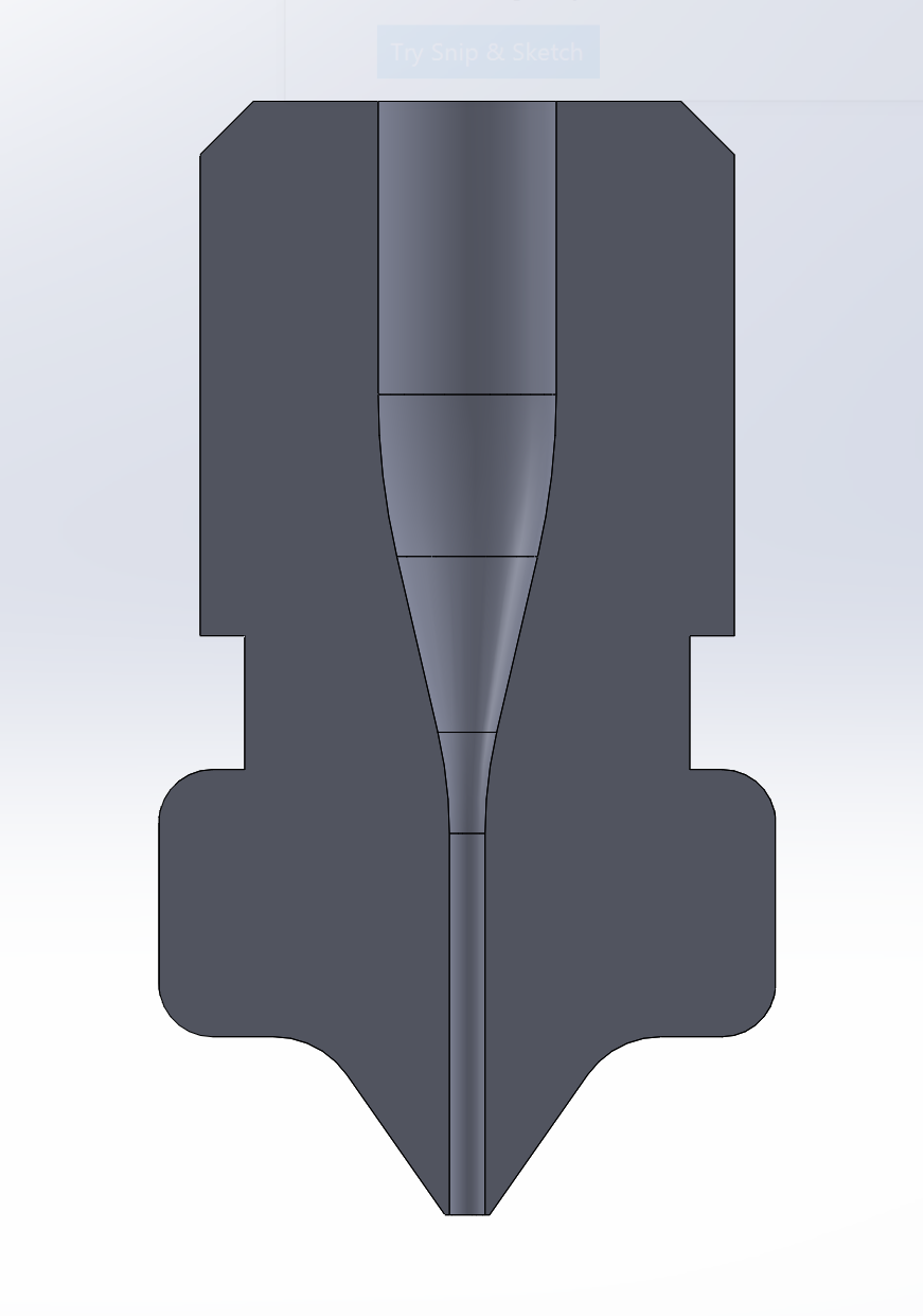
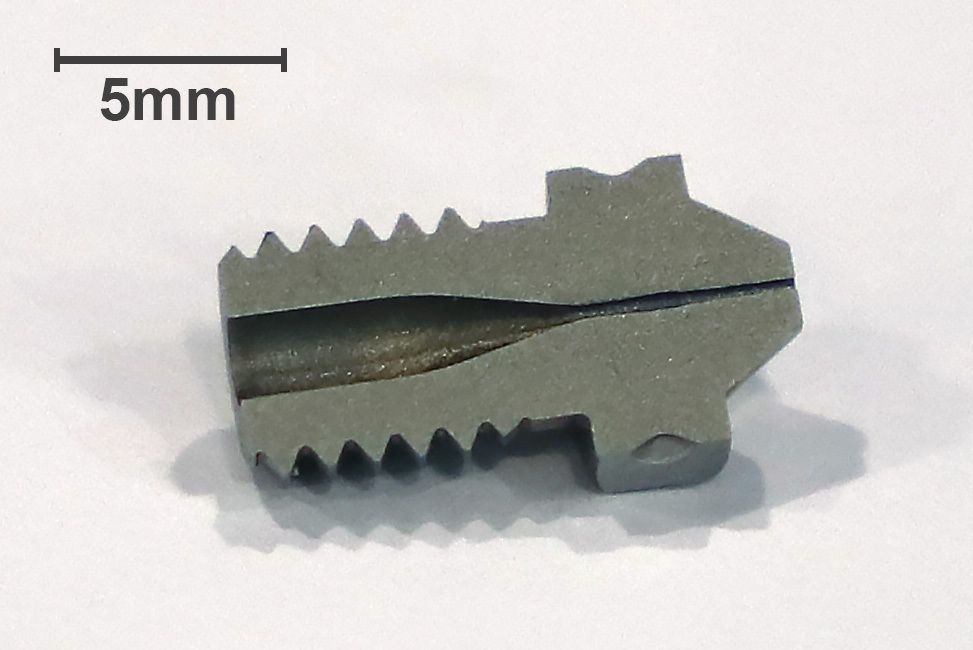
Up next: a nozzle designed with geometry scaled from a traditional extrusion die. The first photo is simply a CAD cross section of the overall design. The next photo is an actual cross section of our first attempt. The manufacturing method is EDM using electrodes cut on a high speed graphite mill. Tolerances are within 0.0005" using these methods. Additionally, surface finish is "perfect", at least perfectly consistent. Machine settings can manipulate how fine or course the finish is, as well as different grades of graphite (we use angstrofine, so most changes here will occur at the machine).
As you can see, right as the major ID begins, the path is a bit wider. This is due to electrode erosion, and the next sample will run additional electrodes to ensure the entire orifice is brought to size. Put simply, the inconsistency is not a manufacturing limitation, but rather having not validated the manufacturing process.
The theory is that this will assist in a) more consistent extrusion width b) less drool, and c) possibly an improved surface finish. Taking things a step further, if there are positive results samples will be vacuum hardened, and ultimately produced from Tungsten Carbide. One of the really great things about EDM, is it does not care about material hardness.
This is in active development, and I will be sure to share updates and progress. I expect the next photos to be actual print comparisons, and the next cross section to be completely straight/uniform. I expect to have to-spec sample by this Friday.
As an aside, the design concept was largely targeted toward pellet extrusion. Initial tests will be done with standard FDM extrusion setups, but high-detail pellet extrusion is the end goal.
I'd love to hear any opinions on this, including other possibilities given the manufacturing methods available.
-
I am a bit puzzled as to what improvements you think you will get from this design. Not criticizing, just really curious ....
Edit: I see that you have outlined your expectations so please disregard the above comment
I see the gentler transition to the nozzle diameter which I am sure leads to better flow but what difference will the user see ?
I see the loooong nozzle output section. I am sure that this will lead to less drooling but also to higher back pressure.I will be following this to see what the outcome will be.
My main thought here is - will the user see enough of a difference to justify the likely super premium price that this nozzle would cost if it went into production.
Finally, thanks for experimenting .... it is nice to see research into the basic nozzle concept which has been pretty much stagnant other than for coatings and base materials.
-
Could this type of geometry be made with a 0.2 mm orifice?
I have a small suspicion that at tiny nozzle diameters, the turbulence in the stream plays a role in inconsistent extrusion at the start and end of paths.
I would love to try one of these nozzles when they are ready.
-
This is a really cool idea. The increase in back pressure in the nozzle is certainly something that improved geometry may be able to deal with.
My initial concern is the ability to keep the tip sufficiently hot. I'm guessing the nozzle length you have protruding from the block is similar to old RepRap/e3d style so shouldn't be any worse than that.
-
@jens55 No worries, I'd rather people be skeptical and ask questions. After all, until testing occurs I am certainly not taking the position that this will make those improvements.
The long major ID is actually designed with respect to extrusion die "standards"; in this case length is 10x the nominal orifice size. I'm hoping this will result in a more consistent extrusion; think about the consistency you want with filament diameter -- I want to achieve something similar with the extrudate from the nozzle. Hopefully this will result in overall more consistent printing, in particular your perimeters on Z.
As for cost, though I admit we are considering commercial possibilities, we are primarily interested in making the best equipment we can. That means real, tangible performance improvement, tooling-grade repeatability (high hardness/tight tolerance), and ancillary services to ensure a lifetime of use if desired, in this case thermal cleaning.
I hope it does not seem like I'm soliciting here; at any point commercial viability is on the table different channels are planned for promotion. With that out of the way, there is no reason we could not hit a price point competitive with current "high end" nozzles on the market ($60-$100) after tooling up. This has just become the best place I've found online to share developments.
@bot Yes, we should be able to make a .20mm orifice nozzle the same way. The issue we will run into is deflection while cutting the electrode, but through some trial and error should be able to get consistent results.
@Adam-V3D Thank you. I'm optimistic we will see improved thermal properties as there will be more material left on the nozzle itself to retain heat. This nozzle is began as an E3d V6 solid blank; exact same over all dimensions.
I would love to hear feedback from anyone with a more robust background in thermodynamics.
-
@plasticfactory Well I got a Masters degree in engineering and was most competent at thermodynamics, unfortunately just not used it since I left university. Were you thinking of a specific question, or just in general?
-
@plasticfactory I love to see practical experimentation.
The length to diameter ratio of 10:1 reminds of laminar flow elements but it has been many years since I had any dealings with such devices. I can see how it would work in a continuous extrusion process but I'd have reservations about back pressure in a start/stop application such as we use in printing. On the other hand, achieving laminar flow would have it's advantages if the flow at the nozzle outlet is otherwise turbulent. I guess there is only one way to find out and that is to do some real life testing.
Please keep us posted on progress.
-
@adam-v3d Well then, lol. Honestly a bit of both. My feeling is that thermal properties may improve given the increase in remaining material, but honestly just don't know without testing. Any insight?
-
@deckingman If the goal is to feed pellets into this, how are air pockets avoided? Or am I misunderstanding and pellets are what's being produced?
-
@kb58 Pellet extrusion would use a very small screw/barrel, with nozzle attached at the end. Air pockets are avoided by melting in the barrel and pushing material forward with the screw. Because of the small scale and intermittent extrusion, pellet extrusion tends to have lots of fluctuation in extrudate size and drooling. As I said, this nozzle is primarily in consideration of known pellet extrusion issues, but I believe the benefits (if any) would translate to both methods of printing.
@deckingman Appreciate it! This is a bit different than the square orifice and you can fully expect additional updates posted here. Your concerns are definitely shared on this end. I'm hopeful that even with the start/stop, the longer die path will essentially help "form" the shape regardless. We will see!
-
@plasticfactory Increased thermal mass will improve temperature stability over time, but i don' think there were problems with that on standard nozzles, certainly won't be any worse. Your CAD clearly differs quite a lot to the real thing at the tip as nozzles have wide flat ends which aids in keeping the tip warm.
the conductivity is not changing.
I think the main change in taking down the diameter of the flow sooner in the path so you have less distance to melt the filament before demanding it to change form. If you just install it straight into a normal v6 you might end up with issues. This is why volcano and super volcano exist, it just increases the surface area to volume ratio to get more energy to the filament per unit of time.
The advantage you do have is that in the thin area you have significantly changed the surface area to volume ratio. You'll be able to control the temperature better, and will have greater chance of getting consistent temperature right to the core of the filament, but you may be too late in the flow path for that to make a difference.
Laminar flow may well produce a better extrude from the nozzle, but the higher mixing of turbulent flow makes it better for heat transfer. I think nozzle flow is quite laminar already though, apart from where the filament contracts into the orifice.
one think I did read in a paper a while back was a suggestion that a large amount of heat transfer into the material actually occurs at the point where the orifice starts, the turbulent flow there and increased pressure cause it. I don't recall the full conclusion of the paper but the smooth change may not necessarily be better.
To be honest though, all the knowledge in the world won't be able to predict if this nozzle will be better or not. Thermal flow and polymers are both super complex. I think you're approach to testing it to find out is 100% the way to go.
-
@adam-v3d said in Advanced nozzle design:
I think the main change in taking down the diameter of the flow sooner in the path so you have less distance to melt the filament before demanding it to change form. If you just install it straight into a normal v6 you might end up with issues. This is why volcano and super volcano exist, it just increases the surface area to volume ratio to get more energy to the filament per unit of time.
I'd try this with a maxiwatt circular heater. EDIT to add: I found maxiwatt heaters to be much more consistent in heating and highly resilient against outside disturbances such as a part cooling fan turning on or any other such effects. So it would be my choice for testing, to make sure heating before the nozzle is optimal.
-
Another thought that is skillfully grabbed out of thin air with absolutely no evidence to back it up:
While going to the accepted standards of extrusion is a good thing. I wonder if it will make that much of a difference. Remember that most commercial extrusion processes do their extruding into air. The flow has to be perfectly laminar because any sort of turbulence as the material exits the nozzle would result in dimensional issues with the end product.
In our case we extrude against a fixed surface, the previous layer, and all kinds of flow disturbances are bound to happen. Further, the fixed surface is a fractional nozzle diameter away so relatively close.I don't know but as I said before, I will be following this closely .... most intriguing!
And no, it certainly does NOT sound like you are soliciting so keep us informed !
-
@adam-v3d said in Advanced nozzle design:
@plasticfactory Increased thermal mass will improve temperature stability over time, but i don' think there were problems with that on standard nozzles, certainly won't be any worse. Your CAD clearly differs quite a lot to the real thing at the tip as nozzles have wide flat ends which aids in keeping the tip warm.
the conductivity is not changing.
I think the main change in taking down the diameter of the flow sooner in the path so you have less distance to melt the filament before demanding it to change form. If you just install it straight into a normal v6 you might end up with issues. This is why volcano and super volcano exist, it just increases the surface area to volume ratio to get more energy to the filament per unit of time.
The advantage you do have is that in the thin area you have significantly changed the surface area to volume ratio. You'll be able to control the temperature better, and will have greater chance of getting consistent temperature right to the core of the filament, but you may be too late in the flow path for that to make a difference.
Laminar flow may well produce a better extrude from the nozzle, but the higher mixing of turbulent flow makes it better for heat transfer. I think nozzle flow is quite laminar already though, apart from where the filament contracts into the orifice.
one think I did read in a paper a while back was a suggestion that a large amount of heat transfer into the material actually occurs at the point where the orifice starts, the turbulent flow there and increased pressure cause it. I don't recall the full conclusion of the paper but the smooth change may not necessarily be better.I really appreciate this response. I agree it's not much of a problem currently, so I'm hoping that this will maintain things, if not negligibly improve them (clearly I'm overly optimistic in general, lol). To explain, the angle used for the tip on the model is clearly not what we are using for blanks. It needs to be updated. The angle, and thus landing area for the flat, is still up for experimentation. I imagine the next step if we see improvements with the extrudate will be to experiment with the tip area.
Again, thank you for the thorough response. It gives me a lot to think about, in particular pull testing. I think layer bonding strength testing will absolutely be required here as a preliminary.
@oliof I have actually used the Maxiwatt pretty extensively. I love the concept, but consistently had issues with it maintaining temperature (260-300*C) and eventually had to move on. It sounds like my unit may have been faulty -- do you think it would be worth trying another? What temperatures are you running with yours?
As an aside, and I may regret posting too much here, but you may find this interesting. It's a nozzle/heater block combo (and 3d printed!). It will use the same flow path as the nozzle above. Now, before anyone says a word I know this may be very impractical in practice. But, I want to see how it performs!

@jens55 I welcome any and all thoughts, fresh perspective helps tremendously! Everything you said are valid concerns -- it's simply not the same process, and we may see no improvement. But, if the amount coming through the orifice is more consistent, I am confident it will improve the print (even if only by some negligibly but measurable amount). It definitely felt like using conventional standards would be a good baseline -- design can always be tweaked based off this is a foundation. And if my optimism bears no fruit... I will let everyone know.
-
@plasticfactory so you can even 3d print the nozzle? All that's left is the controller and wiring, then we can get a proper reprap!
")
In all seriousness, this is all very interesting and thank you for sharing! Do keep us posted
-
@plasticfactory I had no issues whatsoever with the Maxiwatt on a Hemera, but I only ever printed at 250ish max. With a proper PID tune to 270C it didn't buckle once...
-
@oliof Works for me. I'll try another and if issues persist, I will be thorough about config/hardware review. I'm very confident everything was exactly as it should have been, but at high temps it really struggled to keep up. I was also using mine on a Hemera (not that it particularly matters).
Good enough concept to try again, imo.
-
@plasticfactory Re your combined nozzle/heater block idea, this is effectively what a Diamond mixing hot end is and IMO, one of its major drawbacks. Changing a nozzle when it wears out or for other reasons, takes hours rather than seconds (and costs a relative fortune compared to simply changing the nozzle). It also makes it difficult if not impossible to achieve both high thermal conductivity needed to melt the filament with high abrasion resistance needed for some filaments.
-
Regarding the basic premise of following the design rules for an extrusion die - are you referring to dies used for things like aluminum? I'm not an expert, but my understanding is that, those metals are not melted in the process, but are cold-formed as they go through the die. Also, in the case of 3D printing, the plastic is heated into it's plastic region and is not liquid, so I is the laminar vs turbulent flow question really applicable? I guess I should pull out my old heat transfer and fluid mechanical textbooks and see what the equations say. Anyone know a resource for the mechanical properties of our plastics of interest at various temperatures?
-
@mikeabuilder I am using extrusion die standards typical for plastic extrusion; the same standards we start with when designing dies for our extrusion machinery, scaled down. For basic mechanical properties of material, (in my opinion) the best starting point is a) knowing the grade of resin specifically, and b) searching here: https://plastics.ulprospector.com/ (account required, its free) Though this will not provide properties at various temperatures, only its proper processing and formed states. Either way its an excellent resource for this type of thing.