Solved: Leadshine Closed-Loop External Motor Drivers with Duet2
-
So the answer to the gents question about improving print quality is no then..
-
@CaLviNx said in Solved: Leadshine Closed-Loop External Motor Drivers with Duet2:
So the answer to the gents question about improving print quality is no then..
It depends on the setup you are replacing
")
I'm using few leadshine closed loop steppers for some testing (mostly low power laser and some light milling) and compared to some sanguino board with old pololu stepper driver and some second hand el cheapo nema23 I was using for test initially the difference is staggering..
I'll try to find images, I'm sure I saved them, it is very easy to see with laser as with original setup I had issues that line looked "pointy" and not smooth as stepper was not moving at constant speed but was "stopping" after every step and you see that by laser blacking paper more. Also the "points/dots" were not equaly spread on the line but were more concentrated around full and half step positions (no matter if I was using 1/16 microstepping or 1/32 the spread was same). With leadshine (I got both motor and driver from them "matched") the line is straight and smooth
No clue if that would be visible on 3d print (as I don't see that with duet and different nema17 motors I tested) .. so as I said, depends what you are comparing it to. If you compare it to crappy open loop setup - it's better, microstepping is not only allowing for "smooth start" but is actually precise
-
I recently put iHSV servomotors in my sand table and they perform so much better than steppers in that application I'm going to try putting them into my printer. I am not expecting the sort of improvements I saw in the sand table performance, mainly because the application is so much different. In the sand table, I need high speed (1000-1500 mm/sec), high acceleration, and quiet operation, with precision and accuracy being secondary considerations- sand is not a high resolution medium.
In the 3D printer I need low to moderate speed and acceleration, high precision and accuracy, and quiet operation. I think they'l be quiet, but I'm not sure how they'll behave at 3D printing speeds/accelerations. There are many parameters to tune in the driver to optimize performance, but no information in the manual or software about how do actually do the tuning, so I'll probably just run them at the factory default settings and hope for the best.
-
@mrehorstdmd said in Solved: Leadshine Closed-Loop External Motor Drivers with Duet2:
I'll probably just run them at the factory default settings and hope for the best
3D printing speeds should be covered by default settings as we go from ~10mm/sec up to 200mm/sec .. rarely below or above that, this is "inside" the normal range for e.g. milling machines or plazma cutters or wood routers.. thay are usually used for at factory settings and those cut sometimes at much lower speeds than our 10mm/sec and have free moves faster than 200mm/sec so IMHO factory will work perfectly for 3d printer
-
Did you find you have to use the 5V rather than the 3.6v on the expansion board? I just hooked some up and they don’t appear to work using the +/- 3.6V.
I guess I change the wiring to use the 5V and see if that works.
-
@baird1fa I connected the motors directly to the expansion board differential outputs using whatever voltage comes off it and it works fine.
-
Oh, where did you put the 5V power supply that you used then? Or did you run 5V to all the +ve terminals then the -ve to the expansion board? Maybe my issue is I’m hoping to run at the highest steps possible 51200 I think.
-
@baird1fa I just took the output directly off the expansion board. There was no separate 5V power supply.
This is how I wired it- the controller in the diagram is the Duet expansion board:
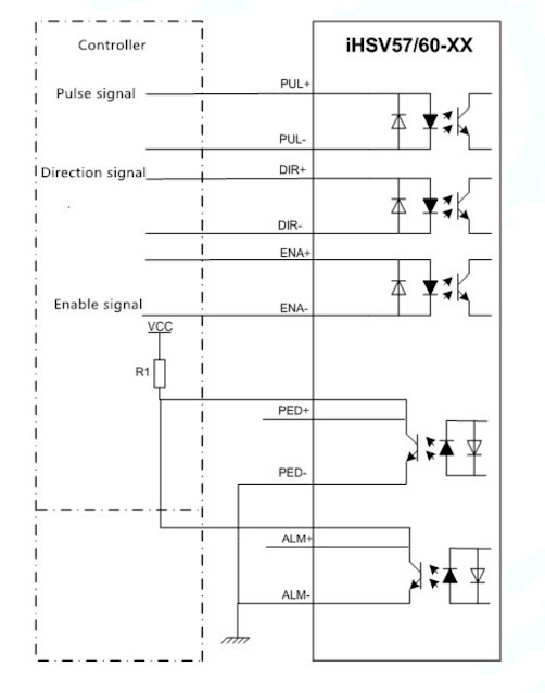
I did not use the alarm outputs so that stuff is not connected.
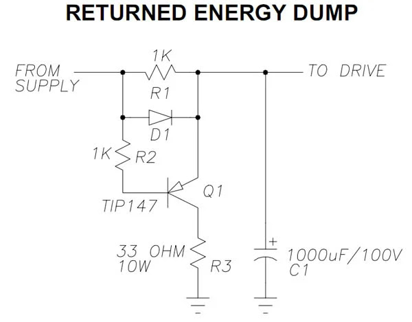
The motor and controller board have their own 24V power supplies (I had an incident...) and I'm adding a protection circuit to prevent power supply over-voltage death (from happening again...).
This is the protection circuit. It protects the power supply and the motor driver which are both connected to the same power supply from overvoltage condition. It operates when the motor voltage is higher than the power supply voltage. That can happen when you get the motor moving really fast and then your mechanism slams into a mechanical stop, stopping the motor suddenly, or just exceeding the motor's rated speed limit. The transistor turns on and shunts the voltage to almost-ground (the 33 Ohm current limiting resistor). Once the normal relationship is restored, Q1 shuts off and the motor and power supply go on as if nothing happened.
-
@baird1fa said in Solved: Leadshine Closed-Loop External Motor Drivers with Duet2:
Did you find you have to use the 5V rather than the 3.6v on the expansion board? I just hooked some up and they don’t appear to work using the +/- 3.6V.
I guess I change the wiring to use the 5V and see if that works.
Did that work for you?
Duet WiFi hardware designer and firmware engineer
Please do not ask me for Duet support via PM or email, use the forum
http://www.escher3d.com, https://miscsolutions.wordpress.com -
I was going to try that this morning but first I’ve connected an oscilloscope to the pul +/- wires to see what signals I can see just to make sure the software is sending pulses. So far I’m not seeing any signals. Just some repeating noise in the range of 30ms. I must have something wrong in my config.g.
Edit: They are working now. I’m not certain what I did to get them working I made some changes to my end stops and my spindle tool and all of a sudden then work, both with the +/- 3.6V and the use of a common 5V positive input.
-
I do not understand where on DUET you wire Alarm signal from the external driver
-
You can wire them into any of the stop inputs. I have used a long ribbon cable to access the e2 and up stop lines for my closed loop steppers.
They trigger a pause command. -
 undefined martin7404 referenced this topic
-
undefined martin7404 referenced this topic