Open-loop for performance, closed-loop for error recovery.
-
I'm seeing several groups attempt to make a closed-loop stepper motor controller using encoder feedback and they are all experiencing the same difficulties everyone does implementing a PID control loop.
- Large errors during speed changes.
- Unstable oscillation
- Differing error performance for long and short moves
- Differing error performance for slow and fast movements
An idea I've never spent much time on (so it's the BEST idea anyone has thought of yet!) is to NOT do PID/closed-loop control for normal movements and only use it to "close-the-loop" during recovery from errors.
The idea is that since we all love the performance of our open-loop steppers with microstepping, and we just want to recover from crashed heads or trying to step too fast causing missed steps, just enable closed-loop mode when you detect the error between actual and commanded position is larger than a setpoint.
When switching in and out of closed-loop mode you'll get blobs and errors in your print, but you had those anyway due to the missed steps that triggered the mode change in the first place.
This method would still require some motor/mechanical-system analysis and tuning, but would not come into play except when there already was an error on printing, and would only be in effect for a short time during the correction of errors phase so it would have much less change of causing catastrophic errors in position compared to a full-time PID loop running.
Anyway, it's an idea and I thought I should bring it up to the team implementing the closed-loop control stuff.
If it's a terrible idea I can live with that. I've had many.
")
-
@alankilian thanks for this - I can see some potential, at least for comparison with the closed loop stepper design we have thus far.
The first step for us will be to add a mode where the 1HCL board runs in openloop, but reports the error from the quadrature encoder compared to the position that the requested (micro)steps set the motor to. That will allow for a comparison of Open Loop with closed loop error (obviously only at the resolution of the encoder we use). For experimentation and characterisation it may make sense to get a higher resolution encoder to get a more accurate characterisation.
We have some priority work to do with the existing closed loop design first, either I or @lirwin17 can provide an update once we have some data for comparison.
-
But open loop motors have no benefits over feedback motors. Quite the opposite. With feedback you can get the maximum performance out of a motor.
-
Perhaps I am missing something but I have used closed loop systems with RRF v3.3 without issue.
Frederick
-
@fcwilt That's excellent news!
- What are you using?
- Have you measured the position error?
-
@alankilian said in Open-loop for performance, closed-loop for error recovery.:
@fcwilt That's excellent news!
- What are you using?
- Have you measured the position error?
Products like these:
I haven't done any error measurements to date, just verified that prints seemed right.
Frederick
-
@t3p3tony said in Open-loop for performance, closed-loop for error recovery.:
the 1HCL board runs in openloop, but reports the error from the quadrature encoder
That's quite handy to tune in the motor current, too. Sometimes too much current reduces the max. possible speed (higher backEMF).
-
Here's a thread where I measured the performance of a similar closed-loop stepper motor controller and found the MEASURED performance quite unacceptable.
It also contains images from a user who gets unacceptable prints. We never heard back if he ever got it working well.
If you're getting good enough prints for you that's an excellent data point and shows that is IS possible to get good prints.
I just haven't quite seen it yet, but there is some hope.
-
@alankilian
This is the system used by shopbottools cncPretty well exactly as you described
https://www.orientalmotor.com/stepper-motors/alphastep-closed-loop-stepper-motors.html
-
MIND BLOWN!!!
-
@alankilian
Someone had a lot of fun making this video! But there's no disturbance in the motion to demonstrate the abilities of closed loop.They could stick a ballpen between the steppers, while they were thumbwrestling.
-
@alankilian said in Open-loop for performance, closed-loop for error recovery.:
I'm seeing several groups attempt to make a closed-loop stepper motor controller using encoder feedback and they are all experiencing the same difficulties everyone does implementing a PID control loop.
Large errors during speed changes.
Unstable oscillation
Differing error performance for long and short moves
Differing error performance for slow and fast movementsThe simple solution is not to use a PID system.
Running the drives/motors in "following error" mode with appropriate gain settings should not cause any instability.
That's how a lot of older industrial CNCs work, and still some new ones.
The motor speed is defined by:
(Difference between the present target position [a virtual value] and the measured position) * a gain factor.As long as the gains are equal for any interpolating axes, path following accuracy is good.
"Look ahead" where PID calculations are added in is a refinement, but can be extremely touchy to set up if the machine mechanical performance, drive system response and measuring system response are not near perfect.
Any performance problems or response delays make it very difficult or impossible to get a system stable with lookahead / PID control and keep a fast response.(Working with industrial CNCs for several decades, including designing and programming a control system from scratch in the early 80s).
-
@rjenkinsgb said in Open-loop for performance, closed-loop for error recovery.:
The motor speed is defined by:
(Difference between the present target position [a virtual value] and the measured position) * a gain factor.That would be identical to a PID system with:
- P = gain
- I = 0
- D = 0
In that system, you ONLY get "Motor speed" when you have a following error.
Speed = error * gainThat CAN be acceptable if you allow a large enough error.
(Note: This error is the difference between the desired position and the actual position, and can be made very very small if you have very high resolution position-measuring system, so "large enough error" might be a fraction of a step of a stepper motor.)Without some mechanical damping (or D coefficient) purely proportional controls like this will oscillate as you attempt to get lower error by increasing the gain. That's just the physics of the situation.
I would be interested in seeing prints from a proportional-only 3D printer as well as the specifications of the position-measurement system to get a feeling for how well they can perform.
My experience says that with a 300-line or 500-line encoder like is available on most stepper systems that a P-only controller will perform extremely poorly.
But I'd LOVE to be shown to be wrong with some prints!
(Reference. Here's PID tuning guide I wrote 21 years ago.)
-
@alankilian said in Open-loop for performance, closed-loop for error recovery.:
That would be identical to a PID system with:
P = gain
I = 0
D = 0In that system, you ONLY get "Motor speed" when you have a following error.
Speed = error * gainA machine too servo drive look-ahead PID system factors in the instantaneous speed that the target point is moving, before any feedback.
A perfectly tuned machine runs with in effect no following error using that system, but it can be extremely difficult to use on an imperfect machine.
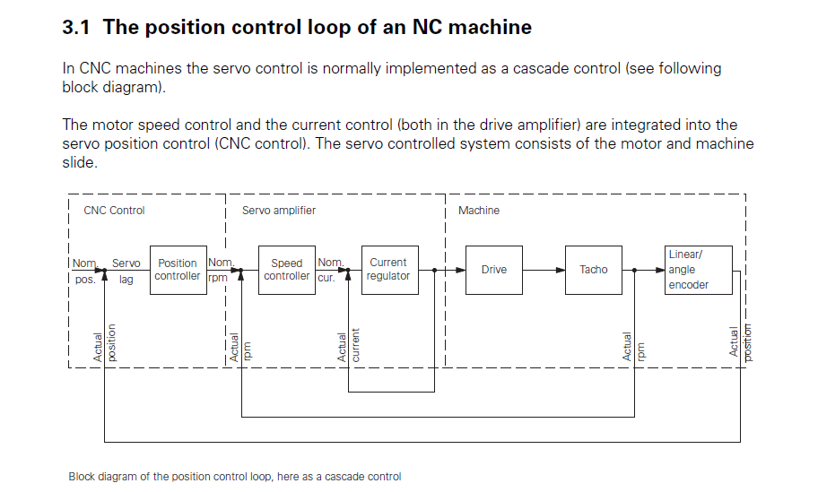
Example block diagram from a Heidenhain manual - note the Velocity input to the system.
That particular diagram is for a DC or BLDC type servo, so includes motor current control. The same concept can be used with a drive system that only has a velocity command input though.
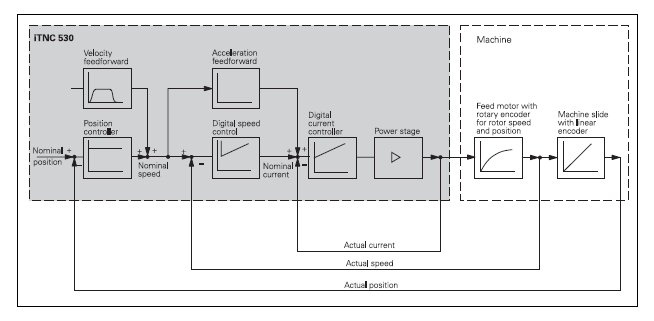
I'm limited for time just now to start looking things up, but if I remember right, in lookahead mode the PID system takes the proportional component from command velocity, the integral from following error and the derivative from feedback velocity.
It's not a simple all-in-one PID as for a heater or whatever.
-
This is the other info I was thinking of, from a 1980s system with separate, analog servo drives.
The lookahead / PID is probably easier to replicate from this version:
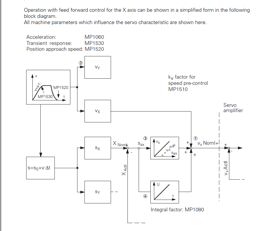
That's the CNC section of this overall drive system diagram:
The control those diagrams relate to (Heidenhain TNC360) runs everything on a 16MHz MC68000 if I remember correctly, for machines operating with multi-axis interpolation and contouring at accuracies down to microns, but with totally separate servo drives.