Maximum Acceleration Calculator
-
@3doeste It should do. The way to treat it is to use the mass to be moved in the Y direction, which is the worse case. That is to say, the mass will be the X carriage plus the X rails and Y carriages. As you rightly say, pure X or pure Y moves will use both motors but 45 degree infill will use only one. So spec the motors as you would for moving Y on a Cartesian.
-
@3doeste I have 2 Hypercube Evolutions and have been doing some testing before the calculator was available. My next Step is to weigh my X and Y moving masses. But the calculator is just a starting point. For example one of my machines is very light so I have also been wondering about jerk that the calculator doesn’t address and which smaller CoreXY s should perform quite well. When I get home from holidays I will see how high I can push jerk.
Another factor is the overall flexibility of the machine, including the belt stretch and associated resonances, X rod flex, hotend mount etc. I have no feel yet for how the belts affect performance - others might be able to comment.I suspect the best acceleration is much lower than the calculator provides, depending on your machine construction and quality preferences.
-
@garis The calculator is for stepper motors only. It is an attempt to calculate the maximum acceleration that a given stepper motor can produce for a given mass.
Whether the rest of the machine is capable of attaining those acceleration values without problems, is of course an entirely different thing.
-
I have a fully machine aluminum CoreXY, I weigh my Y axis and it's around 1500gr of moving mass and my motors have 65n.cm of torque.
The calculator give an aceleration of around 4000, I tried 6000 without problems but used 4000. And with jerk I was using 1800 until I had to do a print with sharp corners and they got wavy in Z (only on corners), so I put the jerk at 600 and it came out perfect, but otherwise, 1800 works great.
I can't get more than 200 mm/s of speed though without losing steps. Perhaps that will improve with 24v and / or 20T pulleys. I have 16T currently. -
CoreXY is complicated.
X axis moves divide the force to accelerate the X carriage by two, split between the motors. Likewise Y axis moves divide the force to accelerate the entire bridge by two. That’s straightforward enough.
Diagonal moves are weeeiiiird. The CoreXY belt path is effectively a sqrt(2):1 compound pulley. IE each 1 mm of diagonal XY travel requires 1.41mm of belt travel, and you get a corresponding force multiplication effect because of that travel ratio. That’s one little-appreciated reason why CoreXY tends to produce nicer prints than an equivalent Cartesian — you’ve effectively geared down the motors.
-
@rcarlyle " That’s one little-appreciated reason why CoreXY tends to produce nicer prints than an equivalent Cartesian — you’ve effectively geared down the motors. "
So is it worth it running at .9deg motor?
-
@og3d depends on your PSU voltage and desired speeds. 0.9 degree motors can only spin half as fast, all else being equal, and CoreXY can only move on diagonals 71% as fast as Cartesian, all else being equal. But the typical 24v Cartesian printer with 1.8 degree steppers can do like 300mm/s without any issues as far as the motors are concerned and people seldom ever go that fast.
-
Well on average the printers usual do not get close to 300mm/s, so on CoreXY using a .9 deg I wont see much improvement vs a 1.8deg motor, since by design CoreXY is geared down. Just making sure I understood it correctly.
I have a delta but at speeds 100mm/s quality is not good and seeing Rail Core II print results at 100mm/s got me inspired to build a CoreXY for my second printer.
-
Hi! Thanks for making this tool, it is very handy.
I'm currently trying to grasp the limitation of accelleration on stepper motor drives. I've used your calculator on a few motors, and i noticed that generally people report running 2-4 times higher accelleration on their printers before running into issues than your calculator says is possible.
I am not sure these printers actually run at the requested speed, but certainly there is some difference between running at the speed your calculator produces and a vastly higher speed, i can see that on my own printer which accellerates more violently.
So i am wondering, what gives? Shouldn't the stepper skip steps if you ask it to go TOO fast? The stepper driver has no feedback loop to tell. I can't notice lost steps below 20.000 mm/s² accelleration using really small NEMA 17 motors with only 1.68 A capability and a rated torque of only 36Ncm, inertia of 54 g/cm² driving a rather heavy gantry at 800gr.
I would really apprechiate if someone could explain this discrepancy to me, i am not very familiar with stepper drives.
-
@genewild said in Maximum Acceleration Calculator:
Hi! Thanks for making this tool, it is very handy.
I'm currently trying to grasp the limitation of accelleration on stepper motor drives. I've used your calculator on a few motors, and i noticed that generally people report running 2-4 times higher accelleration on their printers before running into issues than your calculator says is possible.
I am not sure these printers actually run at the requested speed, but certainly there is some difference between running at the speed your calculator produces and a vastly higher speed, i can see that on my own printer which accellerates more violently.
So i am wondering, what gives? Shouldn't the stepper skip steps if you ask it to go TOO fast? The stepper driver has no feedback loop to tell. I can't notice lost steps below 20.000 mm/s² accelleration using really small NEMA 17 motors with only 1.68 A capability and a rated torque of only 36Ncm, inertia of 54 g/cm² driving a rather heavy gantry at 800gr.
I would really apprechiate if someone could explain this discrepancy to me, i am not very familiar with stepper drives.
You raise some good questions - and unfortunately I'm not the one that can appropriately answer them.
I too see a lot of discussions of folks using acceleration values ~10x what I would expect. A related reason why this and the inverse is true (why the calculator is 10% of what some other folks are using) is because of the below fact:
https://forum.duet3d.com/topic/6/stepper-motors-for-corexy
From: @dc42If you want the motion lag to be no more than one 1/16 microstep during acceleration, then you need to multiply by 9.8%. So the available torque is 65 * 0,85 * 0.71 * 0.098 = 3.8Ncm.
In the past the general consensus was to multiply by the available torque for a given stepper by 9.8% as a sort of factor-of-safety. I follow this factor-of-safety approach.
I recently came across this super cool spreadsheet - however the equations/macros omits the factor-of-safety for available torque, while using it when calculating what the required torque is - the opposite of what I would expect. Here is an example screen grab of a few motors using the equations (without the factor-of-safety):
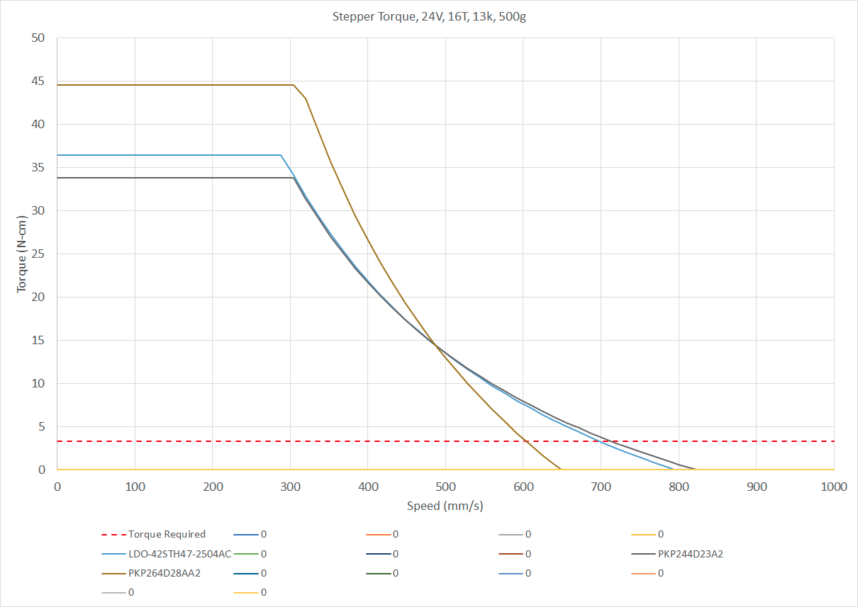
The chart shows the expected speeds at which motor torque begins to drop off - which match the Duet calculations for max speeds here:
https://duet3d.dozuki.com/Wiki/Choosing_and_connecting_stepper_motorsThe issue, to me, is that the red dashed line for torque required is of an extraordinarily low value relative to the stepper curve maximums. A (in my eyes, appropriately allocating the factor-of-safety) corrected chart is below - note the Y-axis changes:
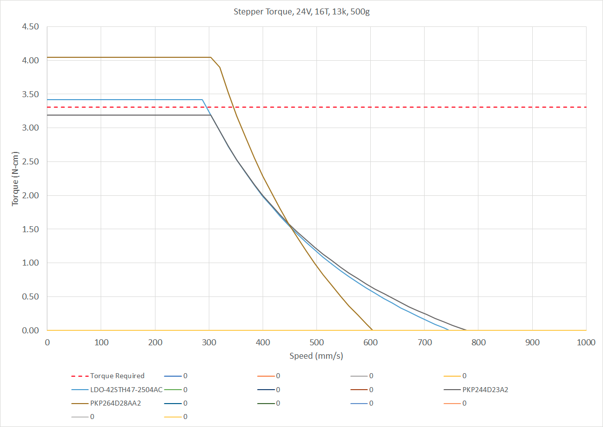
Anyways, more to dig in there. Perhaps @dc42 can go into more detail regarding the motion lag considerations at 1/16th of a microstep. Maybe nowadays that consideration isn't too big of a deal.Side note - but most folks I see using more than, say, 20,000 mm/s^2 acceleration values (on motor/machine setups I would calculate having issues) typically run Klipper. Perhaps issues they may see at such accelerations are reduced by that input-shaping implementation.
-
Hi all. Question: the calculator here https://wilriker.github.io/maximum-acceleration-calculator/ request some data but what is about the case where you dont use pulleys? (axis moved directly using ballscrews for example)
-
@Tinchus said in Maximum Acceleration Calculator:
Hi all. Question: the calculator here https://wilriker.github.io/maximum-acceleration-calculator/ request some data but what is about the case where you dont use pulleys? (axis moved directly using ballscrews for example)
In case of using any kind of screw to directly drive the axis you can approximate the pulley radius by dividing the screw lead by
2π. Remember to before or after convert from whatever unit you used to centimeters (if necessary). The value will probably be a tad bit too large but not in the amount that matters - and you should anyways always remove a security margin.Example
if your screw has a lead of 2mm, i.e. every full rotation results in movement of 2mm, then you divide2mm/2π=0.31831mmDivide that again by 10 to convert it into
cmand you have your virtual pulley radius.