Comparing klipper and RRF input shaper data collection
-
@gloomyandy
I nominate this as macro of the month

-
I've been trying out your script and I think it's working well but I have a couple of questions/comments.
When viewing the resulting .csv file in the Accelerometer plugin the sampling rate (from the last line of the csv file) is auto-set to 28. This is too low and the "Analyze" button does not activate (the minimum appears to be 400). I assume I should change this to 1320 (from "var datarate=1320" in the script) but I have to wonder why the M956 command is writing "Rate 28" to the end of the csv.
In order to make use of the "var axis" variable, lines 41 and 42 should be changed from:
echo >>"/gcodes/vtest.gcode" "G1 X" ^ var.nX ^ " F" ^ var.max_v*60
echo >>"/gcodes/vtest.gcode" "G1 X" ^ -var.nX
to:
echo >>"/gcodes/vtest.gcode" "G1 " ^ var.axis ^ var.nX ^ " F" ^ var.max_v*60
echo >>"/gcodes/vtest.gcode" "G1 " ^ var.axis ^ -var.nX
Thanks for the good work! This is really cool. I especially like that it's collecting so many data points and from both positive and negative directions of movement.
Also, so far sampling with Accelerometer plugin, Input Shaper plugin and your script all agree showing peaks @53 (+/-2) for X&Y on my delta.


-
@ajdtreyd said in Comparing klipper and RRF input shaper data collection:
When viewing the resulting .csv file in the Accelerometer plugin the sampling rate (from the last line of the csv file) is auto-set to 28. This is too low and the "Analyze" button does not activate (the minimum appears to be 400). I assume I should change this to 1320 (from "var datarate=1320" in the script) but I have to wonder why the M956 command is writing "Rate 28" to the end of the csv.
See my notes above:
"To allow me to collect the larger volume of data needed for the klipper runs I had to modify RRF (in this case the STM32 port) to allow more than 64K of samples and also to fix an overflow problem in the data rate calculation when there are a large number of samples being saved."What you are seeing is the effect of the overflow I mentioned in this. I've drawn it to DC42's attention and hopefully it will be fixed in a future version of RRF (it will certainly be fixed in the next release of the STM32 port).
Thanks for the fix, to the variable axis code, this was a late addition and had not been tested when I posted the code!
-
@gloomyandy
Is there a chance to squeeze out even more info with a LIS3D-S-H ?
What would I need to change in the macro (sampling rate)? -
Folks, please be aware that if you use this script with a the current version of RRF (V3.4beta6) or a previous version then you will only be able to collect a maximum of 64K samples (so approx 50 seconds of data, with a sample rate of approx 1320), given that the gcode generated by this script runs for longer than this you may not have good coverage of higher frequencies (as they come later in the test sequence). In my tests I am using a modified (and currently unreleased) version of RRF. Later versions of RRF may make it possible to collect more samples but that is up to @dc42. You may be able to experiment with a capturing the full range by setting your accelerometer to use a lower sampling rate, but this is not something I have tried.
As noted above for reasons I don't currently understand the generated gcode executes faster than simple calculations based on the selected acceleration and distance would indicate. So the best way to select the number of samples to capture (and perhaps make an adjustment to the sample rate to keep it below the 64K sample limit), is probably to time how long the gcode takes to run and then modify the M956 command in the gcode file to adjust the number of samples to collect, you may also want to modify your M955 command if you need to a lower sample rate to capture all of the data.
@o_lampe Hard to say, I doubt if the slightly higher sampling rate or resolution will make much difference in this application. If your accelerometer operates at different sampling rate to 1320 then yes you will need to change that. But it is used to calculate how many samples to collect. But please see the note above about the max number of samples you can currently collect.
-
@gloomyandy said in Comparing klipper and RRF input shaper data collection:
Folks, please be aware that if you use this script with a the current version of RRF (V3.4beta6) or a previous version then you will only be able to collect a maximum of 64K samples (so approx 50 seconds of data, with a sample rate of approx 1320), given that the gcode generated by this script runs for longer than this you may not have good coverage of higher frequencies (as they come later in the test sequence). In my tests I am using a modified (and currently unreleased) version of RRF. Later versions of RRF may make it possible to collect more samples but that is up to @dc42. You may be able to experiment with a capturing the full range by setting your accelerometer to use a lower sampling rate, but this is not something I have tried.
It's been a while since I have had my signal processing classes, so feel free to correct any mistakes, but based on theory each acceleration and deceleration contain all the frequency components. (Ok, this is only true for an infinite acceleration / deceleration, but a fast move should be close enough to capture the frequency range of interest.)
The Klipper approach wiggling the head about is mainly giving you more data and hence a higher resolution of the spectrum which is why you see more noise in the plot.
Btw,. reducing the sampling rate "to capture the full range" will have the opposite effect: the Nyquist–Shannon sampling theorem applies and reducing the sampling rate reduces the maximum frequency that can be sampled which is f_sampling/2.
Voron V2.434 / Duet 3 Mini5+, Duet 3 Expansion Mini 2+, Duet 1LC V1.1 Toolboard
Voron V0.250 / Duet 2 Maestro -
One thing I should have mentioned: these are two fundamentally different approaches to achieve the same thing.
-
Klipper does a sweep where they try to stimulate the system at different frequencies. The ideal input signal for this measurement is a perfect sinusoidal not containing other frequency components, the unknown factor here is how well the sinusoid is approximated by the acceleration/deceleration curves.
-
RRF measures an impulse response based on a fast movement. The ideal input signal here is a very fast acceleration which equally contains all the frequency components of interest. The question here is how well that is achieved.
Both should come to a similar conclusion.
-
-
@pixelpieper Thanks for pointing this out.
Honestly I'm not sure if ramping the frequency helps capture a better data set or not, that is simply the way in which klipper does it and was what I was aiming to investigate. I was just pointing out that at the moment if you use standard RRF and my script you will not be capturing all of that data. From your second post I would have thought that this may be a bad thing if the klipper sweep is operating correctly?
As to the actual sampling rate used again this is a difference between RRF and klipper (klipper typically samples at 3200 samples/s). I have no idea if this is significant or not (it certainly means that klipper will have more samples to process). The shaper tuning only seems to consider relatively low frequencies (a max of 200Hz for RRF and I think something similar for klipper), so in theory so long as the sample rate is above 400 samples/second then it should be usable.
I suspect that one of the key advantages that the klipper method has is that it just provides more usable samples than that produced by the current RRF method. Perhaps it might be better to collect several datasets using the RRF method and combine them to increase the number of usable samples? I'd also note that the current plugin (and the how to use instructions) do not make any mention of what acceleration to use, perhaps it would be better to set a higher acceleration if using this method? I wonder if it would be possibly to apply a higher acceleration value just for the deceleration phase of the move as I assume it is this that provides the impulse in this case?
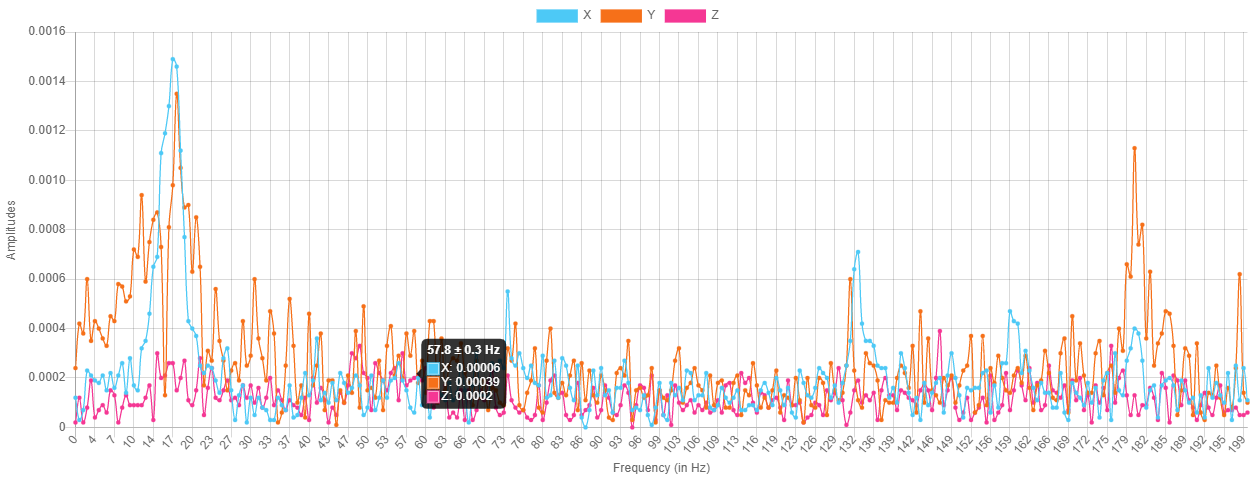
One final thought, I've seen a number of plots that have been produced by myself and other posters in which there seems to be a significant low frequency peak when using the current RRF method, this does not seem to be present with the klipper method. See the first two graphs above, one has a peak around 16Hz that does not seem to be present in the klipper data. I'm not sure which one is correct, but from measuring the ringing on actual prints this peak does not seem match.
-
@pixelpieper said in Comparing klipper and RRF input shaper data collection:
based on theory each acceleration and deceleration contain all the frequency components
Wouldn't it take a certain time for the frame to get into resonance? If so, the frequency in question would need to be applied for longer than just the short accel/deccel time?
-
A quick update. In a previous post I mentioned
There is something a little odd going off with the generated gcode, it does not run for as long as I would expect (approx 130 seconds). I'm not totally sure why, it could be because at the higher frequencies the movement is very small. It may be that jerk has some impact. I'm not sure if this problem is due to my script or the original klipper code.
Jerk does indeed have some impact but that was not the major problem. After running various additional tests and trying to figure out what was going on I reached out to @dc42 and he spotted that the moves being used by this test are not printing moves (as they do not include any extrusion), but I was setting the acceleration for a printing move using M204 P<aaaa>. I have now corrected this by specifying both P and T (just in case!), in the M204 commands. With this change the gcode file now runs for the correct period. Many thanks for your help David!
This has made a small change to the collected data as shown below:
and the data as processed by klipper:
The updated script (which also includes some other small corrections) is:
var title = "Klipper style vibration test V0.3" var axis="Y" var datarate=1320 var stime = state.upTime var min_freq = 5.0 var max_freq = 10000/75 var accel_per_hz = 75 var hz_per_sec = 1 var freq = var.min_freq var max_accel = var.max_freq * var.accel_per_hz var X = 150.0 var Y = 150.0 var sign = 1.0 var t_seg = 0 var accel = 0 var max_v = 0 var L = 0 var nX = 0 var old_freq = 0 var filename = "/gcodes/vtest_" ^ var.axis ^ ".gcode" echo "max_accel " ^ var.max_accel ^ " min freq " ^ var.min_freq ^ " max freq " ^ var.max_freq echo > var.filename " " echo >>var.filename "M201 X" ^ var.max_accel ^ " Y" ^ var.max_accel echo >>var.filename "M205 X0 Y0" echo >>var.filename "G91" echo >>var.filename "M400" echo >>var.filename "G4 S1" echo >>var.filename "M956 P0 A0 S" ^ (var.max_freq - var.min_freq) * var.datarate * var.hz_per_sec echo "Testing " ^ floor(var.freq) echo >> var.filename "echo " ^ var.freq while var.freq < var.max_freq + 0.000001 set var.t_seg = 0.25 / var.freq set var.accel = var.accel_per_hz * var.freq set var.max_v = var.accel * var.t_seg echo >>var.filename "M204 P" ^ var.accel ^ " T" ^ var.accel set var.L = 0.5 * var.accel * (var.t_seg*var.t_seg) set var.nX = (var.sign * var.L) echo >>var.filename "G1 " ^ var.axis ^ var.nX ^ " F" ^ var.max_v*60 echo >>var.filename "G1 " ^ var.axis ^ -var.nX set var.sign = -var.sign set var.old_freq = var.freq set var.freq = var.freq + (2. * var.t_seg * var.hz_per_sec) if floor(var.freq) > floor(var.old_freq) ;echo >> var.filename "echo " ^ floor(var.freq) echo "Testing " ^ floor(var.freq) echo >>var.filename "G90" echo "total time " ^ state.upTime - var.stime -
@gloomyandy Great, thanks!
Just a comment. you have to change the:
echo >>var.filename blablato
echo >>{var.filename} blablaAs described in the meta commands docs:
echo ><filename> <expression>, <expression>, ... where <filename> is either a quoted string or an expression enclosed in { } that evaluates to a string. -
@gixxerfast That's odd, what I posted works fine for me (using an SBC I've not tested it on a standalone system). Have you tried it? Did you get errors?
-
@gloomyandy Yes, I got errors and I run standalone.
For example:
2021-11-18 20:33:03	M98 P"0:/macros/test/resonancetest.g"
max_accel 10000.000 min freq 5.0 max freq 133.3333
Testing 5
Error: in file macro line 31 column 8: meta command: expected string expression
When I fixed as described it seems to work fine and produced the gcode-file
-
@gixxerfast Looks like there is a difference between SBC and standalone macros then @chrishamm
-
@gloomyandy
So. I assume this is the current standalone version of Andys script (with spaces instead of tabs") ) Thanks again!
) Thanks again!var title = "Klipper style vibration test V0.3" var axis="Y" var datarate=1320 var stime = state.upTime var min_freq = 5.0 var max_freq = 10000/75 var accel_per_hz = 75 var hz_per_sec = 1 var freq = var.min_freq var max_accel = var.max_freq * var.accel_per_hz var X = 150.0 var Y = 150.0 var sign = 1.0 var t_seg = 0 var accel = 0 var max_v = 0 var L = 0 var nX = 0 var old_freq = 0 var filename = "/gcodes/vtest_" ^ var.axis ^ ".gcode" echo "max_accel " ^ var.max_accel ^ " min freq " ^ var.min_freq ^ " max freq " ^ var.max_freq echo >{var.filename} " " echo >>{var.filename} "M201 X" ^ var.max_accel ^ " Y" ^ var.max_accel echo >>{var.filename} "M205 X0 Y0" echo >>{var.filename} "G91" echo >>{var.filename} "M400" echo >>{var.filename} "G4 S1" echo >>{var.filename} "M956 P0 A0 S" ^ (var.max_freq - var.min_freq) * var.datarate * var.hz_per_sec echo "Testing " ^ floor(var.freq) echo >>{var.filename} "echo " ^ var.freq while var.freq < var.max_freq + 0.000001 set var.t_seg = 0.25 / var.freq set var.accel = var.accel_per_hz * var.freq set var.max_v = var.accel * var.t_seg echo >>{var.filename} "M204 P" ^ var.accel ^ " T" ^ var.accel set var.L = 0.5 * var.accel * (var.t_seg*var.t_seg) set var.nX = (var.sign * var.L) echo >>{var.filename} "G1 " ^ var.axis ^ var.nX ^ " F" ^ var.max_v*60 echo >>{var.filename} "G1 " ^ var.axis ^ -var.nX set var.sign = -var.sign set var.old_freq = var.freq set var.freq = var.freq + (2. * var.t_seg * var.hz_per_sec) if floor(var.freq) > floor(var.old_freq) ;echo >> var.filename "echo " ^ floor(var.freq) echo "Testing " ^ floor(var.freq) echo >>{var.filename} "G90" echo "total time " ^ state.upTime - var.stimeVoron V2.4 (#1317) with Duet 3 Mini5+ Wifi and 1LC v1.1 Toolboard
Voron V0.1 (#637) with Duet 3 Mini 5+ Wifi and 1LC v1.2 Toolboard
Ender 3 Pro with BTT SKR-2 + RRF -
@gloomyandy said in Comparing klipper and RRF input shaper data collection:
@pixelpieper Thanks for pointing this out.
Honestly I'm not sure if ramping the frequency helps capture a better data set or not, that is simply the way in which klipper does it and was what I was aiming to investigate. I was just pointing out that at the moment if you use standard RRF and my script you will not be capturing all of that data. From your second post I would have thought that this may be a bad thing if the klipper sweep is operating correctly?
Yes.
As to the actual sampling rate used again this is a difference between RRF and klipper (klipper typically samples at 3200 samples/s). I have no idea if this is significant or not (it certainly means that klipper will have more samples to process). The shaper tuning only seems to consider relatively low frequencies (a max of 200Hz for RRF and I think something similar for klipper), so in theory so long as the sample rate is above 400 samples/second then it should be usable.
Yes, as long as we stay above 400 Hz we are fine.
I suspect that one of the key advantages that the klipper method has is that it just provides more usable samples than that produced by the current RRF method. Perhaps it might be better to collect several datasets using the RRF method and combine them to increase the number of usable samples?
That should work and will allow us to do a longer FFT which in turn results in a finer frequency resolution.
I'd also note that the current plugin (and the how to use instructions) do not make any mention of what acceleration to use, perhaps it would be better to set a higher acceleration if using this method? I wonder if it would be possibly to apply a higher acceleration value just for the deceleration phase of the move as I assume it is this that provides the impulse in this case?
Accelleration and decelleration equally produce the same kind of oscillations, it should not matter.
One final thought, I've seen a number of plots that have been produced by myself and other posters in which there seems to be a significant low frequency peak when using the current RRF method, this does not seem to be present with the klipper method. See the first two graphs above, one has a peak around 16Hz that does not seem to be present in the klipper data. I'm not sure which one is correct, but from measuring the ringing on actual prints this peak does not seem match.
Someone earlier in this thread mentioned that Klipper filters very low and high frequency components, hence it is expected that these peaks would dissappear.
Voron V2.434 / Duet 3 Mini5+, Duet 3 Expansion Mini 2+, Duet 1LC V1.1 Toolboard
Voron V0.250 / Duet 2 Maestro -
@o_lampe said in Comparing klipper and RRF input shaper data collection:
@pixelpieper said in Comparing klipper and RRF input shaper data collection:
based on theory each acceleration and deceleration contain all the frequency components
Wouldn't it take a certain time for the frame to get into resonance? If so, the frequency in question would need to be applied for longer than just the short accel/deccel time?
No, this is just the stimmulating signal - the closest equivalent I could think about would be a tuning fork, it just needs a very short tap to resonate for a long time.
-
@pixelpieper said in Comparing klipper and RRF input shaper data collection:
Someone earlier in this thread mentioned that Klipper filters very low and high frequency components, hence it is expected that these peaks would dissappear.
Any filtering in klipper does not really apply in this case. See the first two graphs in my first post, neither of those is using anything to do with klipper and the first image has a very clear peak at 16Hz that is not present in the second image. Both graphs are produced by the RRF accelerometer plugin.
-
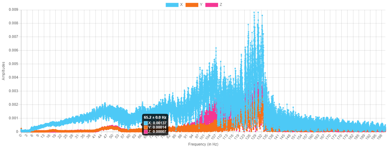
After resolving the issue with the acceleration settings, I've been trying to understand the source of the peaks I was seeing around 100Hz (which only seem to show up in X). I had a close look at my print head and discovered a loose mounting bolt! After tightening this I've re-run all of the tests:
RRF input shaper plugin X data:
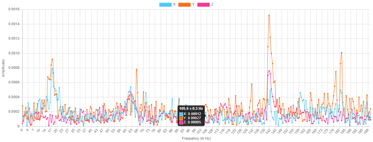
Klipper style X data:
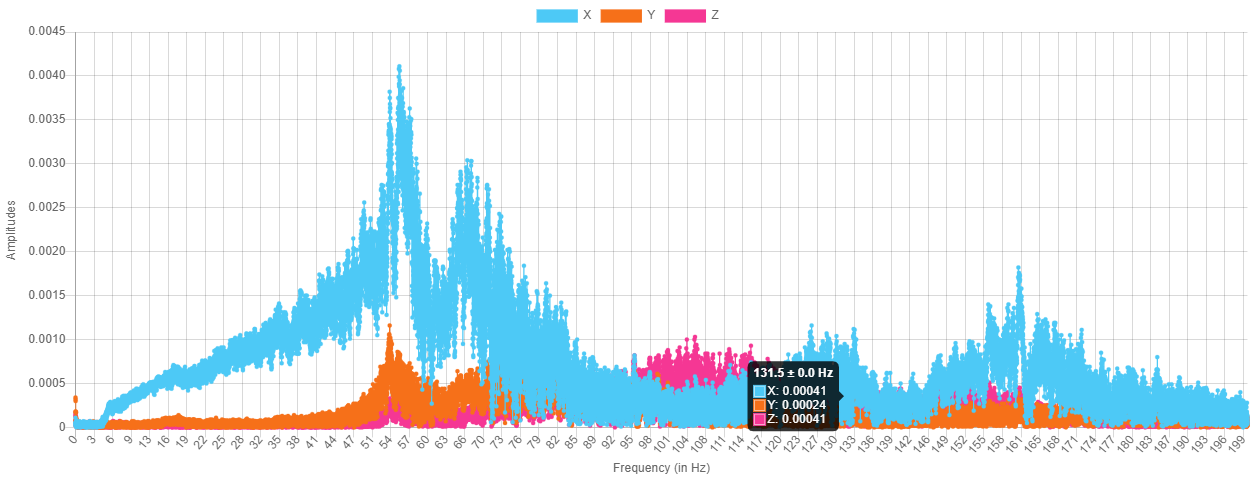
RRF input shaper plugin Y data:
klipper style Y data:
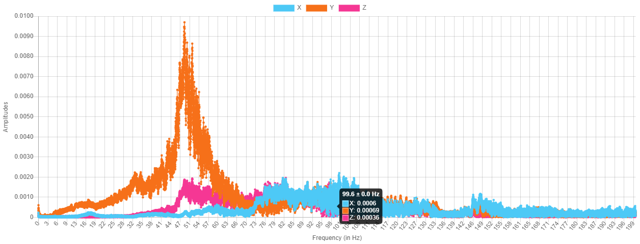
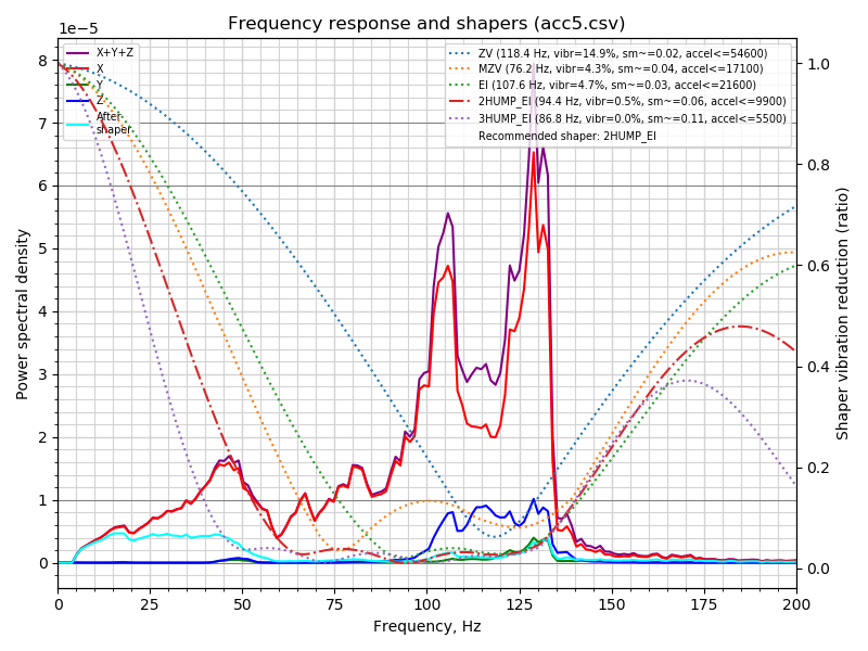
The klipper input shaper script allows you to combine multiple input files, so I used that to produce a recommendation:
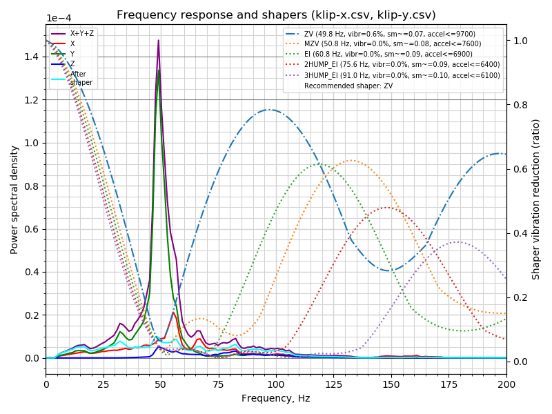
I'm reasonably happy that this output matches the ringing I've been seeing on actual test prints. On these the ringing was worse on Y and measuring them gave a frequency of approx 46Hz.
For me I would say that the klipper style frequency sweep produces better data to analyse than the single move used by the current RRF input shaper plugin.
-
@gloomyandy, i agree with you. I think in the klipper style data you can also see the resonance detected with RRF recording.
My conclusion is to find all or at least most resonances of a printer more test moves are necessary.
Do you agree?