after print part orientation change
-
I try before changing S0 to S1 but nothing change
When I move X and y axis moving right directionBut printing times I don’t know why changing
-
Looks like you are using Simplify3D which has "Flip Build Table Axis" enabled by default for Y:
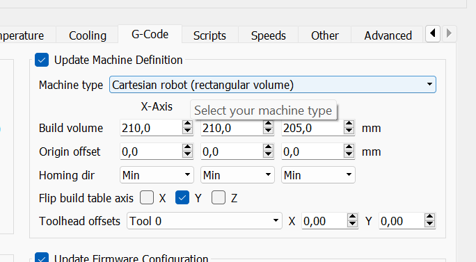
Try disabling that maybe?
-
@oliof
thank you for suggestion. i try right know. is the same . did not change -
if you conduct moves via Duet Web Control, do the axes move in the right direction?
-
@oliof x axis i set g92 x250 and y axis i set g92 y280. when i try to move Duet Web control i need you - side
example i need to move x20 than i need to press x-230 then i reach x20.
i try to many way to fix but no luck .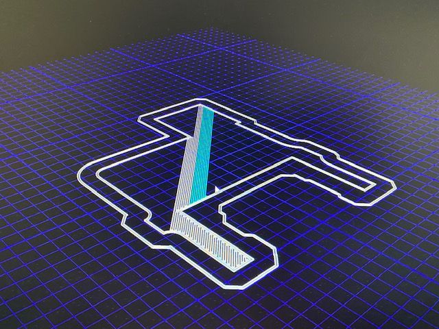
-
@patel said in after print part orientation change:
M208 X0 Y0 Z0.0 S0 ; Set axis minima
M208 X260 Y280 Z215.80 S1 ; Set axis maximaYour M208 S values are reversed.
S0 = set axis maximum, 1 = set axis minimum
-
@phaedrux Thank you for reply
I made corrections but still results is the same -
I believe it is a setting within the slicer:
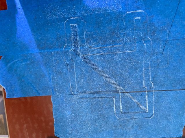
From the initial images, the parts are mirrored within themselves - but the part positions are not exchanged along the same axis, which they would be if it were in any way related to printer movement.
I cannot see how it can be anything but some form of mirror setting within the slicer - possibly done during an early setup, trying to compensate a reversed axis in the printer??
-
@rjenkinsgb said in after print part orientation change:
but the part positions are not exchanged along the same axis
Maybe. I don't think the photo shows the parts on the build surface though. Perhaps they were exchanged?
-
@patel said in after print part orientation change:
@phaedrux Thank you for reply
I made corrections but still results is the sameCan you post your homing files as well please?
Can you confirm for me a few details?
Where are your endstops located? Photo?
When looking at the printer from the front, the 0,0 position should be located at the front left corner.
-X should move to the left, +X should move to the right, -Y should move to the front, +Y should move the back. -
@phaedrux
I send all data tomorrow. We have power outage today
Sorry for delay -
As earlier mentioned, I think you have to rule out some things:
Is your x motor your x motor. (sending gcode)
Is your y motor your y motor. (sending gcode)
Does they rotate in the correct way. (sending gcode)
Does x home before y?
Read your gcode in another slicer (or gcode viewer) and see the result.From there you can troubleshoot. Looks to me you changed x and y.
-
; Configuration file for Duet WiFi (firmware version 3.3)
; executed by the firmware on start-up
;
; generated by RepRapFirmware Configuration Tool v3.3.10 on Sun Dec 12 2021 20:23:27 GMT-0600 (Central Standard Time); General preferences
M575 P1 S1 B57600 ; enable support for PanelDue
G90 ; send absolute coordinates...
M83 ; ...but relative extruder moves
G21
M669 K0; Network
M550 P"My Printer" ; Set machine name
M552 S1 ; Enable networkM586 P0 S1 ; Enable HTTP
M586 P1 S0 ; Disable FTP
M586 P2 S0 ; Disable Telnet; Drives
M569 P0 S0 ; physical drive 0 goes forwards
M569 P1 S1 ; physical drive 1 goes forwards
M569 P2 S0 ; physical drive 2 goes forwards
M569 P3 S1 ; physical drive 3 goes forwards
M584 X0 Y2 Z1 E3 ; set drive mapping
M350 X16 Y16 Z16 E16 I1 ; configure microstepping with interpolation
M92 X87.50 Y87.50 Z1052.20 E476.50 ; set steps per mm
M566 X900.00 Y900.00 Z60.00 E120.00 ; set maximum instantaneous speed changes (mm/min)
M203 X6000.00 Y6000.00 Z180.00 E1200.00 ; set maximum speeds (mm/min)
M201 X500.00 Y500.00 Z20.00 E250.00 ; set accelerations (mm/s^2)
M906 X800 Y800 Z800 E800 I30 ; set motor currents (mA) and motor idle factor in per cent
M84 S30 ; Set idle timeout; Axis Limits
M208 X0 Y0 Z0 S1 ; set axis minima
M208 X260 Y280 Z215.8 S0 ; set axis maxima; Endstops
M574 X2 S1 P"xstop" ; configure switch-type (e.g. microswitch) endstop for low end on X via pin xstop
M574 Y2 S1 P"ystop" ; configure switch-type (e.g. microswitch) endstop for low end on Y via pin ystop
M574 Z2 S1 P"zstop" ; configure switch-type (e.g. microswitch) endstop for low end on Z via pin zstop; Z-Probe
M558 P5 C"^zprobe.in" H5 F120 T6000 ; set Z probe type to switch and the dive height + speeds
G31 P500 X0 Y0 Z2.5 ; set Z probe trigger value, offset and trigger height
M557 X15:215 Y15:195 S20 ; define mesh grid; Heaters
M308 S0 P"bedtemp" Y"thermistor" T100000 B4092 ; configure sensor 0 as thermistor on pin bedtemp
M950 H0 C"bedheat" T0 ; create bed heater output on bedheat and map it to sensor 0
M307 H0 B1 S1.00 ; enable bang-bang mode for the bed heater and set PWM limit
M140 H0 ; map heated bed to heater 0
M143 H0 S120 ; set temperature limit for heater 0 to 120C
;M308 S1 P"e0temp" Y"thermistor" T100000 B4138 ; configure sensor 1 as thermistor on pin e0temp
;M950 H1 C"e0heat" T1 ; create nozzle heater output on e0heat and map it to sensor 1
M307 H1 B0 S1.00 ; disable bang-bang mode for heater and set PWM limit
M143 H1 S280 ; set temperature limit for heater 1 to 280C
M308 S1 P"e0temp" Y"pt1000" ; sensor 1
M950 H1 C"e0heat" T1 ; create heater and map sensor 1
; Fans
M950 F0 C"fan1" Q500 ; create fan 0 on pin fan1 and set its frequency
M106 P0 S0 H-1 ; set fan 0 value. Thermostatic control is turned off; Tools
M563 P0 D0 H1 F0 ; define tool 0
G10 P0 X0 Y0 Z0 ; set tool 0 axis offsets
G10 P0 R0 S0 ; set initial tool 0 active and standby temperatures to 0C; Custom settings are not defined
HOME FILE
; homex.g
; called to home the X axis
;
; generated by RepRapFirmware Configuration Tool v3.3.10 on Wed Dec 15 2021 15:04:17 GMT-0600 (Central Standard Time)
G91 ; relative positioning
G1 H2 Z5 F6000 ; lift Z relative to current position
G1 H1 X-265 F1800 ; move quickly to X axis endstop and stop there (first pass)
G1 H2 X5 F6000 ; go back a few mm
G1 H1 X-265 F360 ; move slowly to X axis endstop once more (second pass)
G1 H2 Z-5 F6000 ; lower Z again
G90 ; absolute positioning; homey.g
; called to home the Y axis
;
; generated by RepRapFirmware Configuration Tool v3.3.10 on Wed Dec 15 2021 15:04:17 GMT-0600 (Central Standard Time)
G91 ; relative positioning
G1 H2 Z5 F6000 ; lift Z relative to current position
G1 H1 Y-285 F1800 ; move quickly to Y axis endstop and stop there (first pass)
G1 H2 Y5 F6000 ; go back a few mm
G1 H1 Y-285 F360 ; move slowly to Y axis endstop once more (second pass)
G1 H2 Z-5 F6000 ; lower Z again
G90 ; absolute positioning; homez.g
; called to home the Z axis
;
; generated by RepRapFirmware Configuration Tool v3.3.10 on Wed Dec 15 2021 15:04:17 GMT-0600 (Central Standard Time)
G91 ; relative positioning
G1 H2 Z5 F6000 ; lift Z relative to current position
G1 H1 Z-220.8 F1800 ; move Z down until the endstop is triggered
G92 Z0 ; set Z position to axis minimum (you may want to adjust this); Uncomment the following lines to lift Z after probing
;G91 ; relative positioning
;G1 Z5 F100 ; lift Z relative to current position
;G90 ; absolute positioning; homeall.g
; called to home all axes
;
; generated by RepRapFirmware Configuration Tool v3.3.10 on Wed Dec 15 2021 15:04:17 GMT-0600 (Central Standard Time)
G91 ; relative positioning
G1 H2 Z5 F6000 ; lift Z relative to current position
G1 H1 X-265 Y-285 F1800 ; move quickly to X and Y axis endstops and stop there (first pass)
G1 H2 X5 Y5 F6000 ; go back a few mm
G1 H1 X-265 Y-285 F360 ; move slowly to X and Y axis endstops once more (second pass)
G1 H1 Z-220.8 F360 ; move Z down stopping at the endstop
G90 ; absolute positioning
G92 Z0 ; set Z position to axis minimum (you may want to adjust this); Uncomment the following lines to lift Z after probing
;G91 ; relative positioning
;G1 Z5 F100 ; lift Z relative to current position
;G90 ; absolute positioning -
; Endstops
M574 X1 S1 P"!xstop" ; configure switch-type (e.g. microswitch) endstop for low end on X via pin xstop
M574 Y1 S1 P"!ystop" ; configure switch-type (e.g. microswitch) endstop for low end on Y via pin ystop
M574 Z1 S1 P"!zstop" ; configure switch-type (e.g. microswitch) endstop for low end on Z via pin zstop -
@patel said in after print part orientation change:
; Endstops
M574 X1 S1 P"!xstop" ; configure switch-type (e.g. microswitch) endstop for low end on X via pin xstop
M574 Y1 S1 P"!ystop" ; configure switch-type (e.g. microswitch) endstop for low end on Y via pin ystop
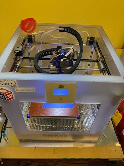
M574 Z1 S1 P"!zstop" ; configure switch-type (e.g. microswitch) endstop for low end on Z via pin zstopWhich is it?
Is the red dot the endstop location for both X and Y?
@phaedrux said in after print part orientation change:
When looking at the printer from the front, the 0,0 position should be located at the front left corner.
-X should move to the left, +X should move to the right, -Y should move to the front, +Y should move the back.Does it move like this?
-
@phaedrux
Yes red dot end stop switch -
@phaedrux
thank you very much you fix my printer .
1 week i am looking problem . lot of search google, lot of change file but what you say When looking at the printer from the front, the 0,0 position should be located at the front left corner.
-X should move to the left, +X should move to the right, -Y should move to the front, +Y should move the back. -
@patel said in after print part orientation change:
@phaedrux
Yes red dot end stop switchIf that's the case, then then endstop definition should be X at low end (M574 X1) Y at high end (M574 Y2) and the homing moves should change to have X move negative to the left and Y move positive to the back.
If those movement directions are no correct, then the motor rotation may need to change in M569. https://duet3d.dozuki.com/Wiki/M569
-
@phaedrux
Know ok
Thank you again for helping me -
undefined Phaedrux marked this topic as a question 16 Dec 2021, 20:39
-
undefined Phaedrux has marked this topic as solved 16 Dec 2021, 20:40