Orbiter 2 extruder mounting for Smart effector with Magball arms
-
@bberger could be. mines on a predator too, although using 450mm arms
-
@jay_s_uk what's the motor (or better how deep is the motor, 17mm? 20mm? 24mm?) you're using on the LGX?
-
@bberger using a 17mm Moons rather than a 20mm LDO
-
@jay_s_uk after toying around im CAD I see why the LGX Lite fits better: it's a symmetrical design with the motor in the center. On the orbiter the motor is heavily offset.
-
-
@bberger my thought about horizontal assymetry is that it will create a turning effect for vertical motion, so it should not be much of a problem for the small incremental z movements whilst printing. I was trying to get the extruder weight as low as possible to minimise the turning moment caused by large and rapid x/y motion. The slightly wider arm spacing should also resist this turning effect better?
-
@amjm22 This is what mine looks like now
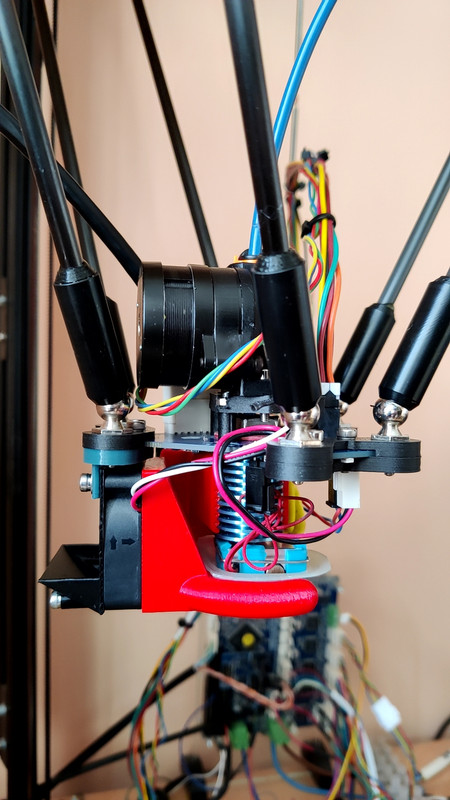
I have made the part cooling fan bracket vertical, and redone the duct - its much easier to get at the mounting screws and adjust the fan height. -
This is what I've tried so far. Just disassembled it and trying something different (all-in-1-adapter for Orbiter + SE).


Will upload pics of my current/latest attempt shortly..
I tried to keep the underside of the effector flat to the adapter so I can reuse my cooling solutions..
-
Just a note:
After ghosting got worse and worse the more I experimented with 80mm spacing I'm back to this:
https://www.thingiverse.com/thing:5162541
+
https://www.thingiverse.com/thing:5253693 (I remixed the excellent 2 arm rigid adapter to be a 3 arm adapter, rigidly mounting the Orbiter v2 adapter from above to the hotend adapter woth 3 screws and additionally the nut).This seems to have solved all my problems and is the clear winner.
No ringing ghosting visible without Input Shaper up to ~4k, with 42Hz MVZ the limit on my machine are the motors now (striking out at ~12k acceleration on the far edges of the bed).
I printed a 23 minute Benchy yesterday with 500mms@10k + Input Shaper (outer walls at 250mms@3k) with basically no defect.
So I'd wager to say: rigidity beats center of gravity in my case. Screwing the rigid 3 arm adapter to the tall Orbiter v2 adapter together tightly was the secret sauce. Didn't work well with just the nut on the V6 M12 heatsink.
I can also run the SE on 25 sensitivity and get excellent results. Deviation < 0.002.
The only thing that's still puzzling me a bit is that 42Hz resonance frequency. It's the same frequency I ended up with all of my tried solutions, be it 55mm spacing with the M12 and the tall adapter, 80mm spacing with the short adapter or the "solid shield". The difference is just the amplitude of it. Mounting the frame on squash feet, using the stock machine damper feet or bolting it to a slab ob granite. All ending up on 42Hz.
Not sure if stiffening my frame would help here, I suspect it's either the PLA-CF carriages on the MGN12 rail bolted to the frame, the belts (6mm geniune Gates RF belt or the Moon's motors themselves..?).
-
@jay_s_uk would you be willing to share the STEP/F3D file on your LGX Mount? Would be using a 20mm motor though and would like to get a starting point on the tilt and offset..
-
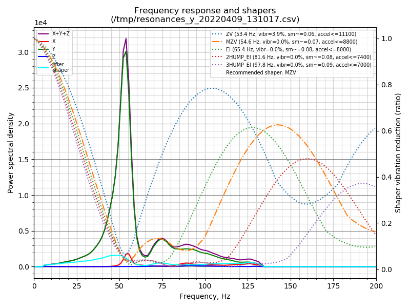
I've settled on a solution for me now. Still undecided if I want to go back to the flying orbiter v2 though as the input shaping graphs don't look too bad, but compared to the flying extruder don't look too good either.. and I'm kinda into getting prints done as fast as I can:
Direct Drive Orbiter v2 on 80mm adapter:
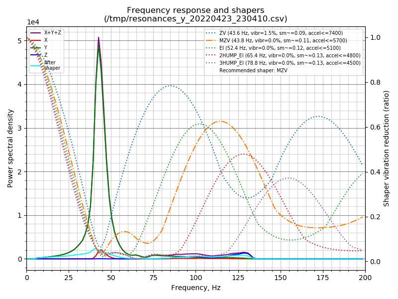
Flying Orbiter v2 on stock 55mm Smart Effector:
Flying Orbiter v2 on 80mm Adapter for reference what the 80mm adapter alone does to my input shaper graph:
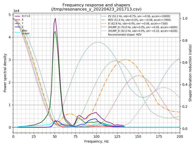
//Edit: the graphs only tell half the truth. I can't even get close to max suggested accelerations on the direct drive without having motion artifacts (no ringing, but "smoothing" from hell). Need to go down to about 2.5k to have comparable print quality to the flying extruder on 8.5k acceleration.
I'll be reverting back and just get a second printer for printing flexibles.
-
@bberger Have you redesigned a LGX lite mount for the Smart Effector?
I spend quite some time lately on pushing my SR with a flying LGX Lite so I would like to compare with a direct drive. -
@fred-y I don't have a solution that I'm happy to share tbh (80mm rod spacing adapter + a pain in the butt mount for the LGX lite).
That LGX Lite is a pain to mate to the smart effector and any adapter I had thought of. The pain of a need to screw them from the bottom is real.
BUT: on the SR I suspect you could probably get away with this without losing print volume:
https://www.thingiverse.com/thing:5255358It doesn't print really well though and needs supports.
-
@bberger Thanks for the link, I didn't see this one the other day when I did a search.
On my other printers I have a 2 parts mount for the LGX Lite because of these screws on the bottom; Maybe I should be looking at doing the same or just give up.On a side note, the other day I realized something about how we mount the extruder on the SE - I have not an expert on kinematic / force but with the extruder mount attached on the effector we apply the filament pressure on the 3 screws.
When doing high speed printing this pressure is fairly high.I was wondering if we could be looking at reusing the thread from the hotend by this way there is no (or very little) pressure on the PCB but I'm worry about the impact for the probe.
The 3 holes on the PCB could just be used to stabilize everything.I'm just sharing the idea ... what do you think?
-
Just to add that I have updated the orbiter 2 mount, posted at https://www.thingiverse.com/thing:5402227
I have made small changes including thickening the top mount and extruder mount, and kept the 55 mm magball spacing. I have recently started using a revo micro extruder, so have included a part cooling duct for that.
The revo seems to have a higher melt rate than the v6 I was using previously, so I have been able to print at 250mm/sec, with 300mm/sec travel speed, with very good results. -
@fred-y though about exactly that multiple times. Problem is that it's pointless with 55mm magball spacing as you need some real nasty vertical offset and tilt to jot collide with the arms which then puts a lot of direct force onto the hotend itself.
-
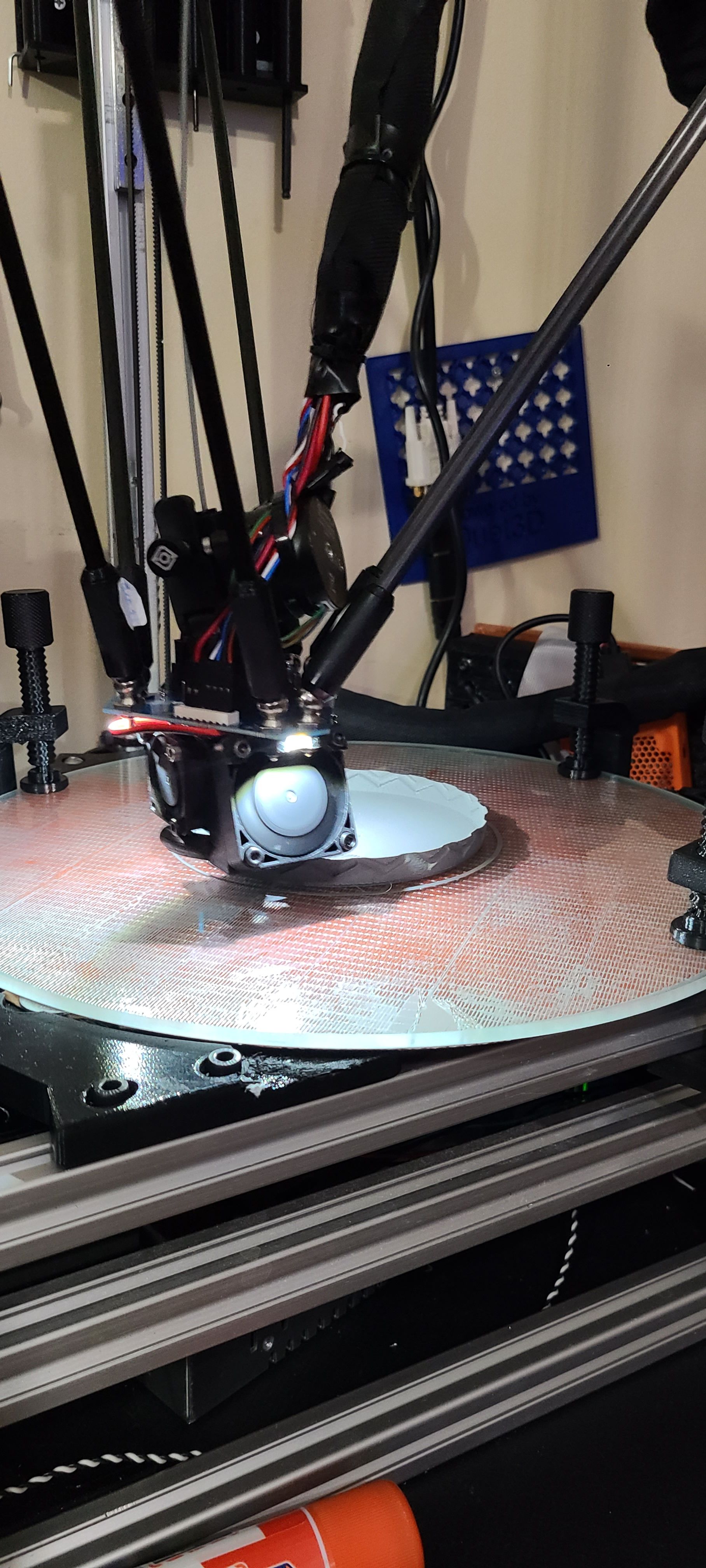
@bberger I find that the 55mm spacing (which I wanted to use to avoid changes to carriages) works well with a 12mm extension - the extruder can be horizontal (filament path vertical). Here is my setup in the furthest -Y position, where the arms are closest to the extruder motor.
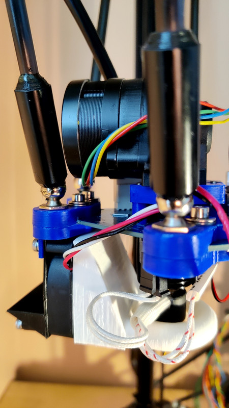
The gap between the extruder platform and the top of the hotend is about 1mm:
 , giving the shortest possible filament path. I would have thought that as the downward force during extrusion is symetrically distrubuted, the strain on the effector/hotend should not be a problem.
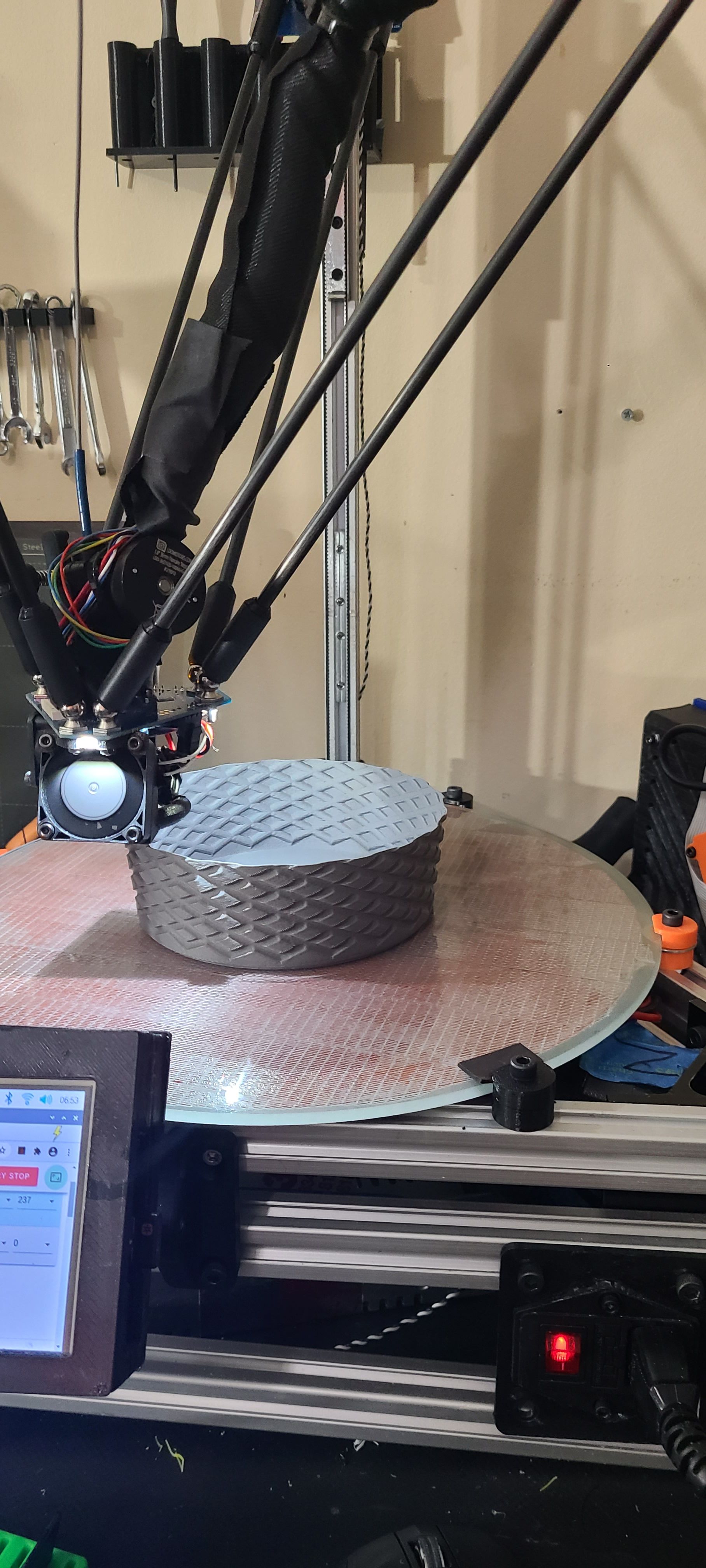
These puzzle pieces, which are about 40mm long and 14mm high, were printed at 250mm/sec, with 300mm/sec travel.
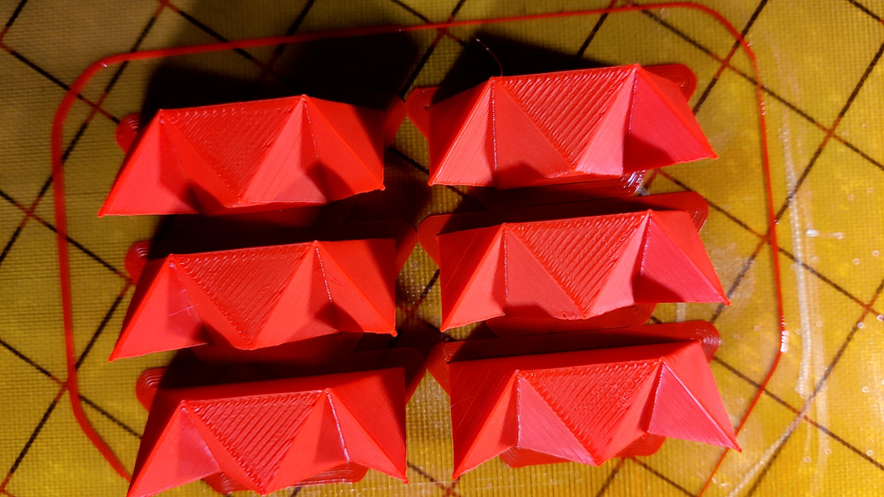
The pieces fit together to make and Escher solid:
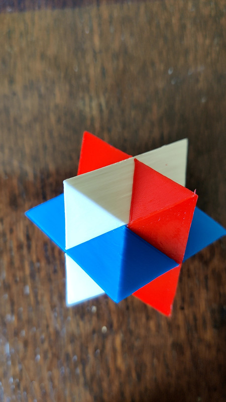
We have just had a jubilee here in the UK - hence the red white and blue. The pieces have to be very precise to fit together with no gaps. -
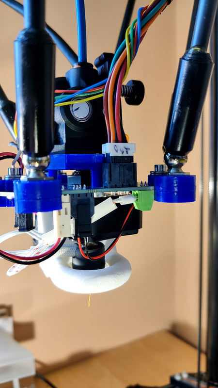
@fred-y Thanks for this idea - it seems to work. I made this:
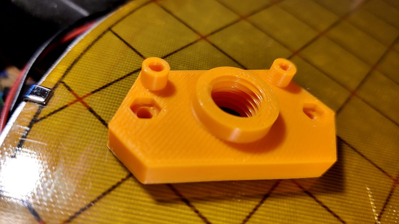
using the two holes on the motor side of the extruder. This leaves a nice gap on the molex connector side for the plug to fit properly.
This is how it looks in situ:
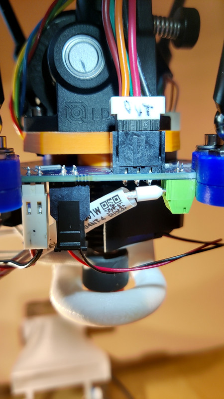
I am using the default sensitivity on a v3 smart effector, and found that it needed an extra -0.04 on the probe offset. Seems to work well though - a 19 point G32 gave a 0.010 fit.
The mount pictured was printed with the new setup - I was fine tuning the thread diameter - 12.3mm was good for me. I havent pushed the new setup yet - seems promising though.
-
@adrian52 That's really nice!
You've done exactly what I was thinking about, I'm happy to know it works.I will definitively spend a little bit of time on Fusion360 this week to try something for the LGX Lite on either my SR or Predator.
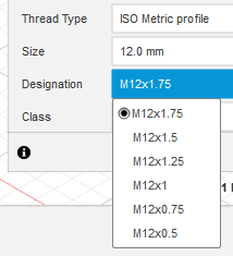
What is pitch of the thread on the heatsink?
-
@fred-y Its 1.5mm.
You do need to be able to rotate your hot end - would be difficult with a v6 where the heater block really has to be aligned with the part cooling fan