New heated enclosure printer
-
@lael I'm not concerned so much with getting it to stick while printing as getting it to unstick when done. Lots of people have good results with ABS using a PEI build sheet, but most of those printers have removable build plates which make removal a lot easier if it does not pop off when cooling and contracting. Due to the size, heater, etc., my build plate main structure is fixed in the machine so I have to get the print off without too much strenuous activity or make a removable secondary layer that does not inhibit heat flow.
-
@coseng yep, that's fair. I think most materials won't inhibit heat flow that much. CF and CF are insulators, but that just means they take a couple of mins to get to temp. Once they are at temp, they maintain it fine.
In terms of plates, I would think removable would make life easier, regardless of what that is, unless the plate is wider than the door
")
-
@lael said in New heated enclosure printer:
@coseng yep, that's fair. I think most materials won't inhibit heat flow that much. CF and CF are insulators, but that just means they take a couple of mins to get to temp.
Well, not really. A temperature is one thing, but in a 3D printing situation we are more concerned with heat (energy) flow, which is driven by a temperature difference and limited by thermal resistance of the materials it is being transmitted through. With a thermally isolating build plate material you would need a higher build plate temperature to be able to get the same energy transfer to the part being built.
Once they are at temp, they maintain it fine.
That's because they do not want to give up the energy they were just given! And that is a problem because we are only heating the build plate to get heat (energy) into the part being built.
That is why I am surprised that the popular nozzle material is brass. Yes, it is easy to machine but it also a relatively poor thermal conductor and significantly limits the amount of heat that can be transferred from the heating element to the filament inside the nozzle bore, which limits the melt rate, which limits the overall print rate.
In terms of plates, I would think removable would make life easier, regardless of what that is, unless the plate is wider than the door
Yes, I agree. The aluminum plate can't come out because the heater and its wires are glued to the bottom. That's why I was thinking a secondary thin aluminum sheet with the PEI on it could be removed and not limit heat transfer from the plate into the part.
-
Making some small progress on the printer in between a bit of actual paying work!
For a little cross-pollination, I used my LCD resin printer with Siraya Sculpt Ultra White high temp resin to print a bracket for the printhead that holds the PCB, BL Touch, water cooling lines and filament tube anchor. It sits on top of the heated chamber, so didn't want to use a normal FDM plastic part.

The resin says good to 220C. It was tested to about 130C with a 30 min soak, well higher than it should ever experience. I loaded it a bit by pushing on it while at temp in the oven, and was impressed by the part's strength. When cool, it feels just like Bakelite.

I have to print another one due to forgetting a wire harness feature, so will put the old one in and test as hot as my toaster over will go to see if I can get a failure.
-
You might want to check the temp rating on the linear rails. Most of them are rated around 85c and the plastic parts are nylon which melts at around 120. It's possible the thermal expansion binds them beyond that.
You'll also want to use grease that works at high temperatures and doesn't melt away.
-
@roiki11 said in New heated enclosure printer:
You might want to check the temp rating on the linear rails. Most of them are rated around 85c and the plastic parts are nylon which melts at around 120. It's possible the thermal expansion binds them beyond that.
I am keeping an eye out on it. The 4 Z carriages are insulated from the chamber and have a fan and cool air path. The Z leadscrew nut is all metal just in case. The dual Y rails sit a couple of inches above and to the side of the chamber and are in clear air. The X carriages are the biggest concern as they are directly above the heated chamber, but are isolated by at least the bellows. There is a fan output available on the LC1 board, so if needed ducting and active cooling for the carriages can be done.
-
@coseng Where did you get those bellows? what material are they?
-
@tinchus said in New heated enclosure printer:
@coseng Where did you get those bellows? what material are they?
They are polyester, from Centryo and they say should be good to 105C.
-
Sorry all for the big drop off! Some paid work, a bout of Covid and life getting in the way of fun things made me temporarily put this on the back burner. Now that all that fuss is done with, it's back to getting this baby finished.
FYI, if anyone is in the NYC area and is interested in some gainful employment, please DM me. Lots of wiring and some hand fabrication and then as much more fabrication on other motorcycle projects as can be handled over the next two months.
Back to the printer. Since the XYUV motion structure was complete, the next item was to fabricate the Z carriage. I finally got to cutting up the CF sheet in to the various pieces for the Z carriage:

Then drilled a bunch of holes:

Then made a bunch of steel angle brackets:

These are all bolted/epoxied together in a semi-monocoque structure that will be plenty rigid with a low thermal expansion for the Z axis stage. The previously machined steel C channel in the left side of the image is the anchor to the Z stage.

The top plate will have three receptacles for a 3 point heated bed support:

Now onto installing the Z axis motion structure into the enclosure. Then comes the electronics layout and wiring (HELP!!!!!) and then initial alignment and commissioning.
Looking forward to getting this baby running!
Also, a quick question for @dc42 . I saw on another thread that the 6XD board was nearing completion. Having one of these would save me a bunch of tweaky hand wiring to pull the step and direction signals off my 6HC and making the jury rigged level shifter to send to the clearpath stepper servos that are being used on the XYUV axes. Is there any chance of a 6XD board being available in the next few weeks?
-
@coseng said in New heated enclosure printer:
Is there any chance of a 6XD board being available in the next few weeks?
I doubt it. https://forum.duet3d.com/topic/27183/time-line-for-duet-3-6xd/7?_=1646971687203
-
@phaedrux OK, thanks.
Chris
-
OK, the Z carriage is assembled and mounted and super rigid.

Access for removing large parts should be good.

Now that all the mechanics are at least installed, next week it is time to mount up all the power and control electronics and start wiring this baby up!
-
My sense of timing is spot on, just as things get close to completion, I break my left collarbone. And I'm a leftie. Oh well, slow progress is still progress, right?
One armed is still enough to work on the electronics, so last week I was able to mount all the components and get most of the AC and DC lines wired up.
SSR control for the internal fan/heater assemblies and the Keenovo AC bed heater. Standard 24VDC AC/DC power supply for all the logic, fans, small heaters, and a switching 75VDC motor power supply with external capacitor for absorbing back-generation.
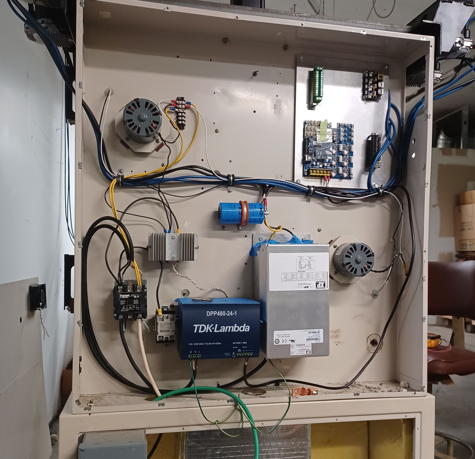
Today I finished the roach wiring to the back of the 6HC board to tap the step and direction signals for stepper drivers 1-4. The ribbon connector is permanently epoxied in place. It is not the neatest modifications but the solder connections seem strong and nothing is shorted. I am curious about the solder used for the DC in terminals, it seemed a lot higher melt temp than for the signal lines.
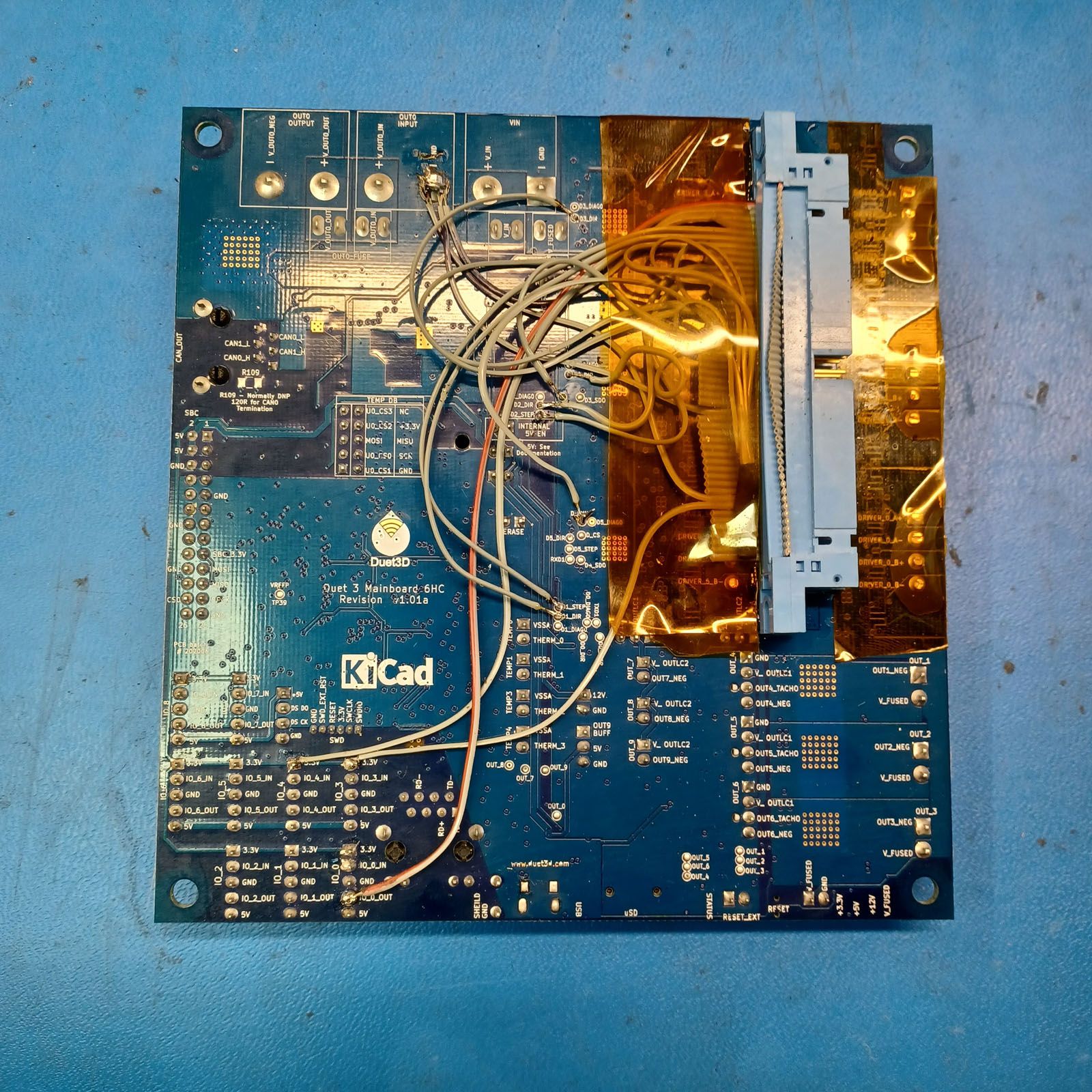
I'll run a 50 pin flat cable from this hacked connector to the Duet 2 BoB to get the 5V signals that the ClearPath motors want to see.
I have an assistant coming in for the next few days so hopefully he can get the aluminum bed and leveling mounts machined and mounted so I can then install the bed heater lines, power up the electronics and do initial commissioning and alignment. And fixing any wiring errors!
-
Finished up assembling and wiring the XY printhead with the 1LC toolboard. Using it really makes wiring quite manageable.

Just getting more details on the build plate and wiring done and have a couple of questions for those more experienced than me:
-
What should the Z homing procedure be? With a BL Touch on the main printhead, is there a need for a separate travel limit switch?
-
For the chamber temp sensor, is using the thermistor included in an E3D extruder (I upgraded to a PT1000 for the hot end) good or is there too much thermal mass to give a fast enough response time? I was planning on running two thermistors wired in series and placed in different locations.
-
Any suggestions for a commissioning sequence of events? I'm starting with only one printhead to keep things somewhat manageable.
Thanks, I can't wait to get this thing moving!
-
-
Some more progress today with the headed bed installed on the Z carriabe with its cable carrier and lots of system wiring done. It is not the neatest layout, but the wiring and connectors are solid and sould not cause any problems. Tomorrow I will actually power it up and check all the lines and hopefully be able to start moving the axes.


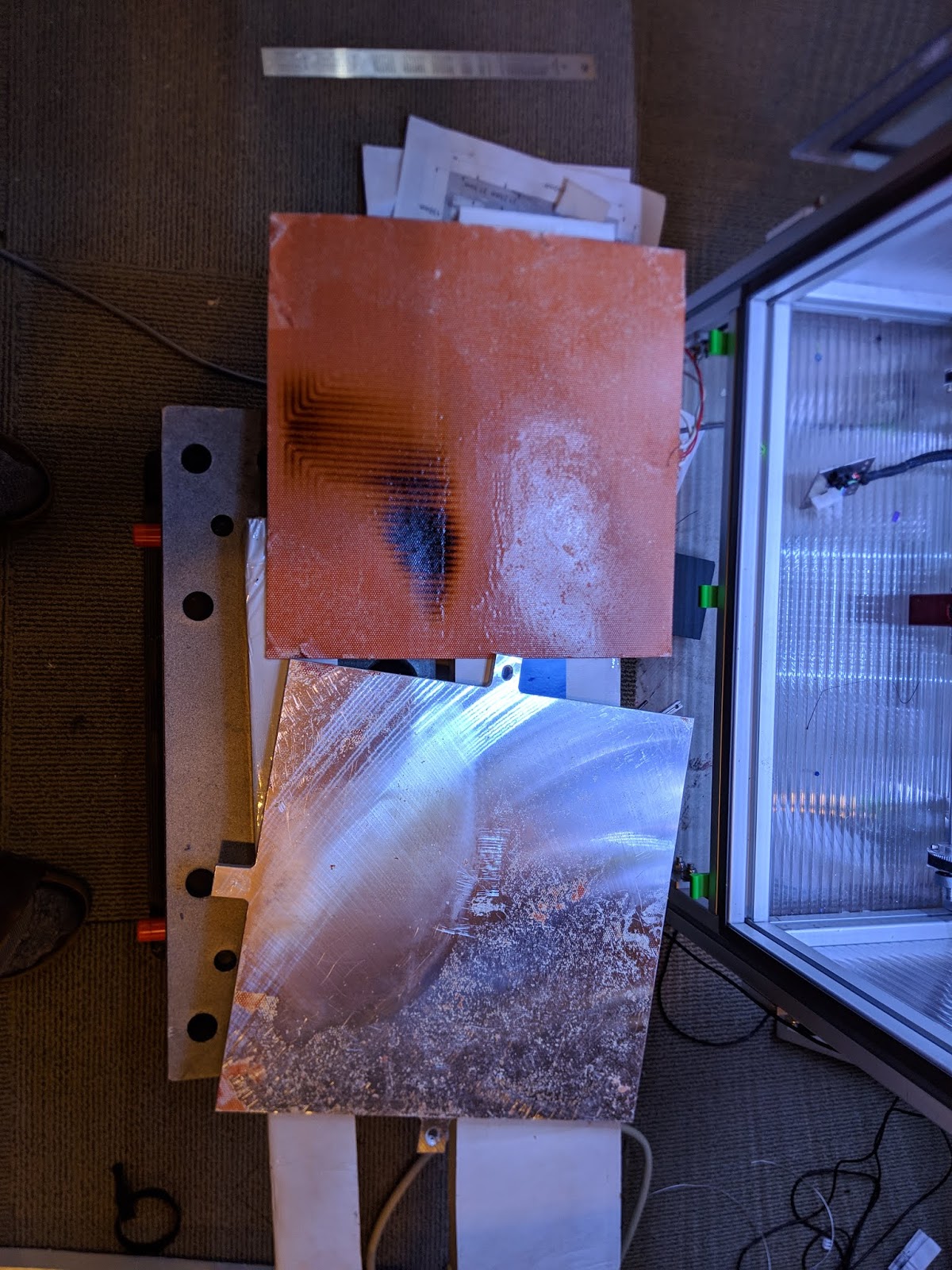
Had a brain fart and ended up cutting the aluminum build plate a bit short on the X axis, hence the silicone heater hanging over the edges. Damn! I hope it does not come back to bite me in the ass.
-
@coseng The bed plate acts as a heat sink for the heater. In the exposed areas the heater may get much hotter than the areas covered by the plate. I had the adhesive on a heater let go a couple years ago creating air bubbles between the heater and the plate. In the areas with the bubbles the heater burned.
-
@mrehorstdmd Ugh, I didn't think of that, thanks for pointing it out. Oh, well, I can put some thinner sheet in those areas to get the heat out.
-
Doing some last wiring and have a question on the paneldue 7i. I would like to use that SD card, so would use the 4 wire connector to IO_0 and the modified 10 pin ribbon cable to the temp daughterboard connector. Is the card detect modification to the 7i pcb necessary or is it just a convienence?
-
@coseng Actually, I have a paneldue 7i 2.01, so the card detect signal is present, so the last question is no longer relevant.
-
OK, I was able to get it all connected to the PC, uploaded RRF3.4 and was able to set the network parameters and get to the Duet Web Control page on a browser.
I did have some issues with the paneldue7i, so any advise you can offer is appreciated, @dc42 .
The paneldue 7i was connected and seemed to respond very slowly to any touch commands. I had the 4 wire and the modified 10 pin ribbon connector attached. I went to upgrade the paneldue 7i firmware according to https://docs.duet3d.com/User_manual/RepRapFirmware/Updating_PanelDue. It seemed to complete successfully, there were no errors in the console and the last message was:
Progress: 100%
Writing PanelDue flash options
Restarting PanelDueAfter the update the paneldue was completely a white screen. I tried pressing reset with no change. I powered it all down then back up and was able to reconnect to the Duet web page, but still nothing from the paneldue 7i but a white screen. Can you brick a paneldue?
Before trying the PC/usb approach I wanted to see if there was something I was doing wrong with the Duet approach.