New heated enclosure printer
-
@roiki11 said in New heated enclosure printer:
You might want to check the temp rating on the linear rails. Most of them are rated around 85c and the plastic parts are nylon which melts at around 120. It's possible the thermal expansion binds them beyond that.
I am keeping an eye out on it. The 4 Z carriages are insulated from the chamber and have a fan and cool air path. The Z leadscrew nut is all metal just in case. The dual Y rails sit a couple of inches above and to the side of the chamber and are in clear air. The X carriages are the biggest concern as they are directly above the heated chamber, but are isolated by at least the bellows. There is a fan output available on the LC1 board, so if needed ducting and active cooling for the carriages can be done.
-
@coseng Where did you get those bellows? what material are they?
-
@tinchus said in New heated enclosure printer:
@coseng Where did you get those bellows? what material are they?
They are polyester, from Centryo and they say should be good to 105C.
-
Sorry all for the big drop off! Some paid work, a bout of Covid and life getting in the way of fun things made me temporarily put this on the back burner. Now that all that fuss is done with, it's back to getting this baby finished.
FYI, if anyone is in the NYC area and is interested in some gainful employment, please DM me. Lots of wiring and some hand fabrication and then as much more fabrication on other motorcycle projects as can be handled over the next two months.
Back to the printer. Since the XYUV motion structure was complete, the next item was to fabricate the Z carriage. I finally got to cutting up the CF sheet in to the various pieces for the Z carriage:

Then drilled a bunch of holes:

Then made a bunch of steel angle brackets:

These are all bolted/epoxied together in a semi-monocoque structure that will be plenty rigid with a low thermal expansion for the Z axis stage. The previously machined steel C channel in the left side of the image is the anchor to the Z stage.

The top plate will have three receptacles for a 3 point heated bed support:

Now onto installing the Z axis motion structure into the enclosure. Then comes the electronics layout and wiring (HELP!!!!!) and then initial alignment and commissioning.
Looking forward to getting this baby running!
Also, a quick question for @dc42 . I saw on another thread that the 6XD board was nearing completion. Having one of these would save me a bunch of tweaky hand wiring to pull the step and direction signals off my 6HC and making the jury rigged level shifter to send to the clearpath stepper servos that are being used on the XYUV axes. Is there any chance of a 6XD board being available in the next few weeks?
-
@coseng said in New heated enclosure printer:
Is there any chance of a 6XD board being available in the next few weeks?
I doubt it. https://forum.duet3d.com/topic/27183/time-line-for-duet-3-6xd/7?_=1646971687203
-
@phaedrux OK, thanks.
Chris
-
OK, the Z carriage is assembled and mounted and super rigid.

Access for removing large parts should be good.

Now that all the mechanics are at least installed, next week it is time to mount up all the power and control electronics and start wiring this baby up!
-
My sense of timing is spot on, just as things get close to completion, I break my left collarbone. And I'm a leftie. Oh well, slow progress is still progress, right?
One armed is still enough to work on the electronics, so last week I was able to mount all the components and get most of the AC and DC lines wired up.
SSR control for the internal fan/heater assemblies and the Keenovo AC bed heater. Standard 24VDC AC/DC power supply for all the logic, fans, small heaters, and a switching 75VDC motor power supply with external capacitor for absorbing back-generation.
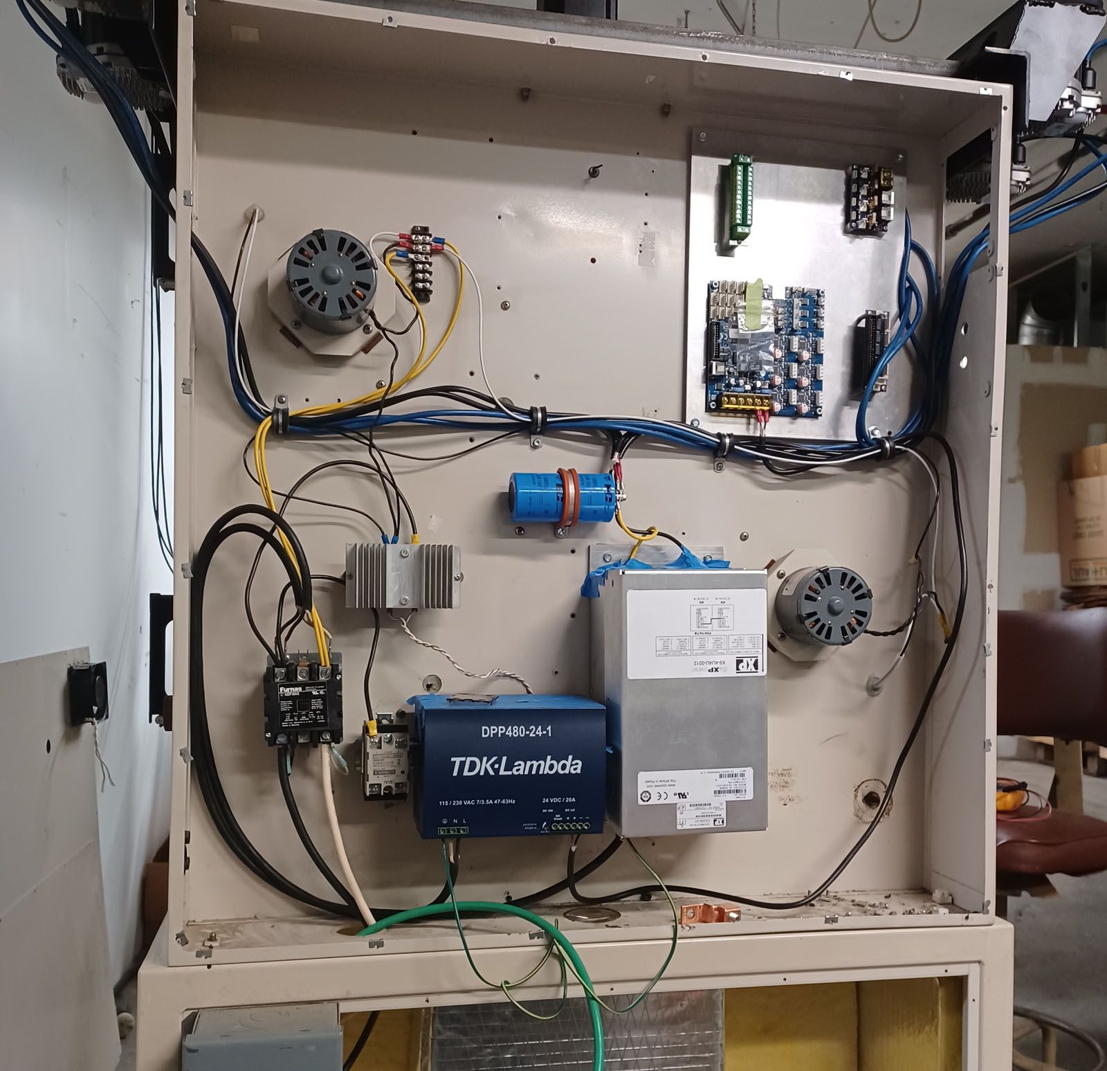
Today I finished the roach wiring to the back of the 6HC board to tap the step and direction signals for stepper drivers 1-4. The ribbon connector is permanently epoxied in place. It is not the neatest modifications but the solder connections seem strong and nothing is shorted. I am curious about the solder used for the DC in terminals, it seemed a lot higher melt temp than for the signal lines.
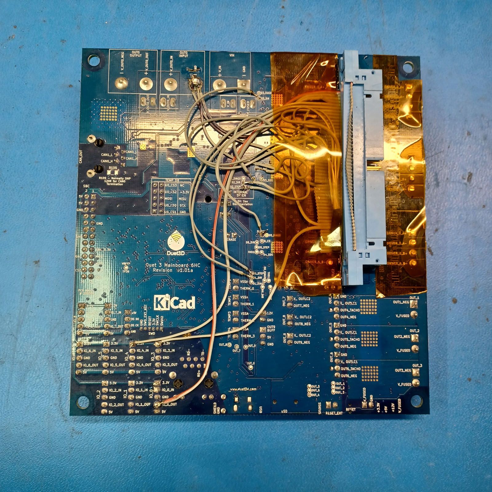
I'll run a 50 pin flat cable from this hacked connector to the Duet 2 BoB to get the 5V signals that the ClearPath motors want to see.
I have an assistant coming in for the next few days so hopefully he can get the aluminum bed and leveling mounts machined and mounted so I can then install the bed heater lines, power up the electronics and do initial commissioning and alignment. And fixing any wiring errors!
-
Finished up assembling and wiring the XY printhead with the 1LC toolboard. Using it really makes wiring quite manageable.

Just getting more details on the build plate and wiring done and have a couple of questions for those more experienced than me:
-
What should the Z homing procedure be? With a BL Touch on the main printhead, is there a need for a separate travel limit switch?
-
For the chamber temp sensor, is using the thermistor included in an E3D extruder (I upgraded to a PT1000 for the hot end) good or is there too much thermal mass to give a fast enough response time? I was planning on running two thermistors wired in series and placed in different locations.
-
Any suggestions for a commissioning sequence of events? I'm starting with only one printhead to keep things somewhat manageable.
Thanks, I can't wait to get this thing moving!
-
-
Some more progress today with the headed bed installed on the Z carriabe with its cable carrier and lots of system wiring done. It is not the neatest layout, but the wiring and connectors are solid and sould not cause any problems. Tomorrow I will actually power it up and check all the lines and hopefully be able to start moving the axes.


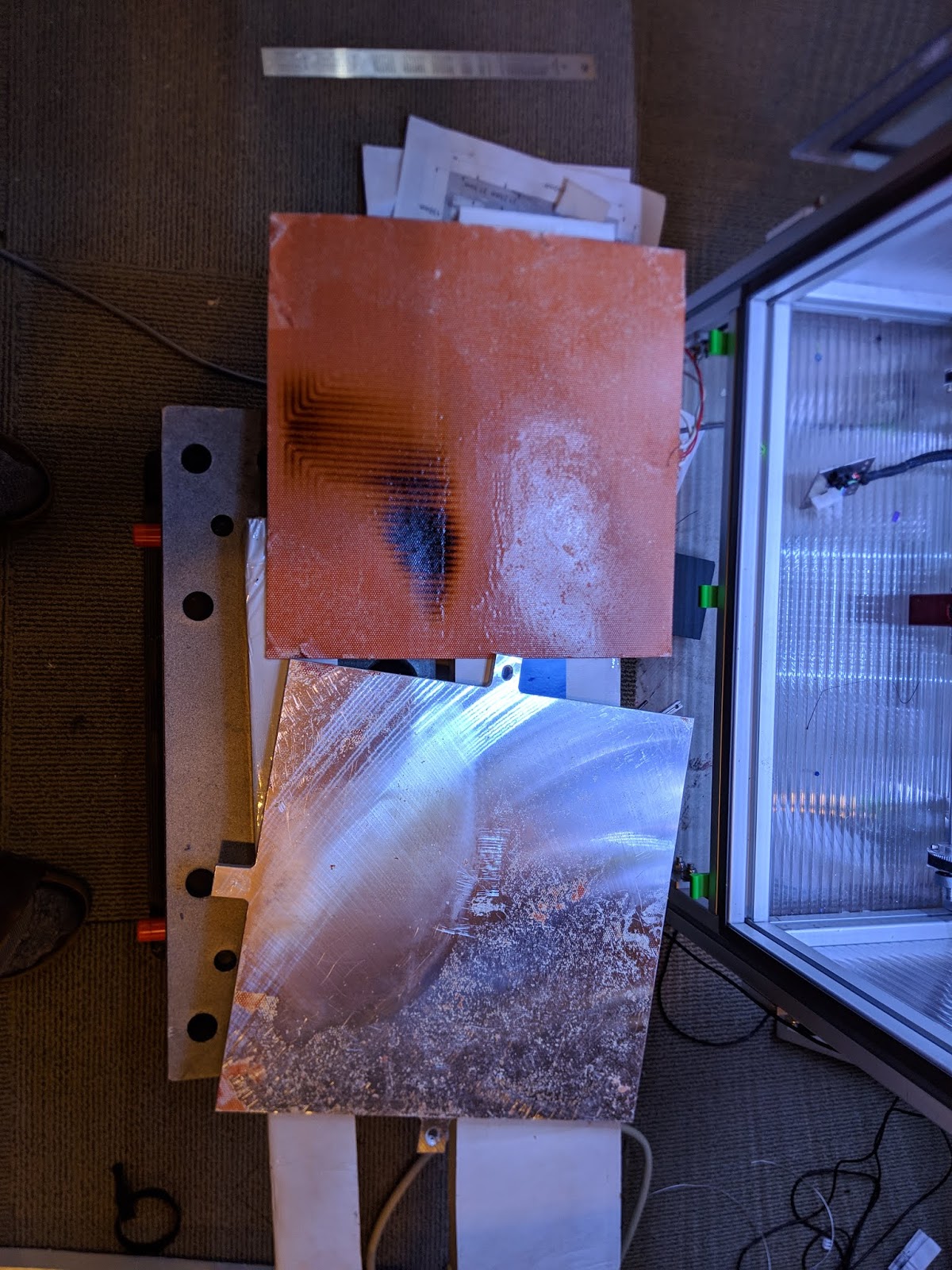
Had a brain fart and ended up cutting the aluminum build plate a bit short on the X axis, hence the silicone heater hanging over the edges. Damn! I hope it does not come back to bite me in the ass.
-
@coseng The bed plate acts as a heat sink for the heater. In the exposed areas the heater may get much hotter than the areas covered by the plate. I had the adhesive on a heater let go a couple years ago creating air bubbles between the heater and the plate. In the areas with the bubbles the heater burned.
-
@mrehorstdmd Ugh, I didn't think of that, thanks for pointing it out. Oh, well, I can put some thinner sheet in those areas to get the heat out.
-
Doing some last wiring and have a question on the paneldue 7i. I would like to use that SD card, so would use the 4 wire connector to IO_0 and the modified 10 pin ribbon cable to the temp daughterboard connector. Is the card detect modification to the 7i pcb necessary or is it just a convienence?
-
@coseng Actually, I have a paneldue 7i 2.01, so the card detect signal is present, so the last question is no longer relevant.
-
OK, I was able to get it all connected to the PC, uploaded RRF3.4 and was able to set the network parameters and get to the Duet Web Control page on a browser.
I did have some issues with the paneldue7i, so any advise you can offer is appreciated, @dc42 .
The paneldue 7i was connected and seemed to respond very slowly to any touch commands. I had the 4 wire and the modified 10 pin ribbon connector attached. I went to upgrade the paneldue 7i firmware according to https://docs.duet3d.com/User_manual/RepRapFirmware/Updating_PanelDue. It seemed to complete successfully, there were no errors in the console and the last message was:
Progress: 100%
Writing PanelDue flash options
Restarting PanelDueAfter the update the paneldue was completely a white screen. I tried pressing reset with no change. I powered it all down then back up and was able to reconnect to the Duet web page, but still nothing from the paneldue 7i but a white screen. Can you brick a paneldue?
Before trying the PC/usb approach I wanted to see if there was something I was doing wrong with the Duet approach.
-
@coseng said in New heated enclosure printer:
Before trying the PC/usb approach I wanted to see if there was something I was doing wrong with the Duet approach.
Use the PC/USB approach. Chances are you had an older version of PanelDue firmware on there that wasn't ready for updating via duet.
-
@phaedrux Thanks, that worked!
Now a couple of more questions. Below is my first config.g file. I have not run it yet as I have to run a new AC power socket to plug into, so all of my playing around so far has been only with the USB and network cable attached.
First question from the RRF config tool on i/o mapping tab: PWM Control Channel (BLTouch only) should be set to what value? The BL Touch channels selected on the prvious page are not selectable on this drop down. I left it not assigned, but on the next page the BLTouch entry was greyed out. the BLTouch is on a 1LC toolboard. and all 5 wires are connected as shown in the wiki, so am not sure what this is referring to or how it would be wired.
I have a Z limit switch at about z=0 (or can be positioned wherever is convienent) and a BL Touch. What is the preferred way to home Z? Is the limit switch even needed?
I am running the 5V line that supplies the BoB with power to generate proper level clearpath signals from IO_3_out. What would be the command to turn this output on to power the steppers?
Also, not sure if it should work with no 24V supplied, but the Paneldue 7i upgraded fine and displayed a proper screen when plugged into a USB cable, but when plugged into the 6HC (powered by usb) with a 4 wire connector and 10/7 pin ribbon cable (both are correct) it only gives me a white screen and does not respond to touches. Also, a reset does not seem to do anything.
; Configuration file for Duet 3 (firmware version 3.3)
; executed by the firmware on start-up
;
; generated by RepRapFirmware Configuration Tool v3.3.10 on Wed Apr 13 2022 22:08:04 GMT-0400 (Eastern Daylight Time); General preferences
M575 P1 S1 B57600 ; enable support for PanelDue
G90 ; send absolute coordinates...
M83 ; ...but relative extruder moves
M550 P"hyperprinter" ; set printer name
M669 K1 ; select CoreXY mode; Wait a moment for the CAN expansion boards to start
G4 S2; Network
M552 P192.168.2.1 S1 ; enable network and set IP address
M553 P255.255.255.0 ; set netmask
M554 P192.168.2.20 ; set gateway
M586 P0 S1 ; enable HTTP
M586 P1 S0 ; disable FTP
M586 P2 S0 ; disable Telnet; Drives
M569 P0.1 S1 ; physical drive 0.1 goes forwards
M569 P0.2 S1 ; physical drive 0.2 goes forwards
M569 P0.0 S1 ; physical drive 0.0 goes forwards
M569 P121.0 S1 ; physical drive 121.0 goes forwards
M584 X0.1 Y0.2 Z0.0 E121.0 ; set drive mapping
M350 X32 Y32 Z8 E16 I1 ; configure microstepping with interpolation
M92 X56.14 Y56.14 Z320.00 E837.00 ; set steps per mm
M566 X900.00 Y900.00 Z60.00 E120.00 ; set maximum instantaneous speed changes (mm/min)
M203 X6000.00 Y6000.00 Z1800.00 E1200.00 ; set maximum speeds (mm/min)
M201 X500.00 Y500.00 Z20.00 E250.00 ; set accelerations (mm/s^2)
M906 X300 Y300 Z3900 E1600 I30 ; set motor currents (mA) and motor idle factor in per cent
M84 S30 ; Set idle timeout; Axis Limits
M208 X-320 Y-290 Z0 S1 ; set axis minima
M208 X320 Y290 Z950 S0 ; set axis maxima; Endstops
M574 X1 S1 P"121.io2.in" ; configure switch-type (e.g. microswitch) endstop for low end on X via pin 121.io2.in
M574 Y1 S1 P"io1.in" ; configure switch-type (e.g. microswitch) endstop for low end on Y via pin io1.in
M574 Z1 S2 ; configure Z-probe endstop for low end on Z; Z-Probe
M950 S0 C"io7.out" ; create servo pin 0 for BLTouch
M558 P9 C"121.io0.in+121.io0.out" H5 F120 T6000 ; set Z probe type to bltouch and the dive height + speeds
G31 P500 X0 Y0 Z2.5 ; set Z probe trigger value, offset and trigger height
M557 X-300:300 Y-250:250 S100 ; define mesh grid; Heaters
M308 S0 P"temp0" Y"pt1000" ; configure sensor 0 as PT1000 on pin temp0
M950 H0 C"out0" T0 ; create bed heater output on out0 and map it to sensor 0
M307 H0 B0 S1.00 ; disable bang-bang mode for the bed heater and set PWM limit
M140 H0 ; map heated bed to heater 0
M143 H0 S120 ; set temperature limit for heater 0 to 120C
M308 S1 P"temp1" Y"pt1000" ; configure sensor 1 as PT1000 on pin temp1
M950 H1 C"out1" T1 ; create chamber heater output on out1 and map it to sensor 1
M307 H1 B0 S1.00 ; disable bang-bang mode for the chamber heater and set PWM limit
M141 H1 ; map chamber to heater 1
M143 H1 S280 ; set temperature limit for heater 1 to 280C
M308 S2 P"121.temp0" Y"pt1000" ; configure sensor 2 as PT1000 on pin 121.temp0
M950 H2 C"121.out0" T2 ; create nozzle heater output on 121.out0 and map it to sensor 2
M307 H2 B0 S1.00 ; disable bang-bang mode for heater and set PWM limit
M143 H2 S320 ; set temperature limit for heater 2 to 320C; Fans
M950 F0 C"out4" Q500 ; create fan 0 on pin out4 and set its frequency
M106 P0 S1 H-1 ; set fan 0 value. Thermostatic control is turned off
M950 F1 C"out5" Q500 ; create fan 1 on pin out5 and set its frequency
M106 P1 S1 H-1 ; set fan 1 value. Thermostatic control is turned off
M950 F2 C"121.out2" Q500 ; create fan 2 on pin 121.out2 and set its frequency
M106 P2 S1 H-1 ; set fan 2 value. Thermostatic control is turned off; Tools
M563 P0 D0 H1:2 F2 ; define tool 0
G10 P0 X0 Y0 Z0 ; set tool 0 axis offsets
G10 P0 R0 S0 ; set initial tool 0 active and standby temperatures to 0C; Custom settings are not defined
Thanks again for all the help on this project!
Chris
Cosentino Engineering -
@Phaedrux One more question, I saw the paneldue initialization line at the top of config.g, but nothing metioning the SD card access through the temperature daughterboard connector: M950 D1 C"spi.cs0+spi.cs2" . Does this need to be added manually or does the M575 take are of it?
-
@coseng said in New heated enclosure printer:
M558 P9 C"121.io0.in+121.io0.out"
It's not showing the PWM control channel in the drop down because you somehow have both of them selected for the probe input.
You can manually edit the config.g to correct it like this.
; Z-Probe
M950 S0 C"121.io0.out" ; create servo pin 0 for BLTouch
M558 P9 C"121.io0.in" H5 F120 T6000
@coseng said in New heated enclosure printer:
Does this need to be added manually or does the M575 take are of it?
You'll have to manually add that
-
@phaedrux OK, got that taken care of. Was confused that the Modulation Pin needs to be not defined.
I installed AC power and powered it up. Nothing smoked, so that was a good step. I do of course have a couple of problems:
-1LC toolboard is not in CAN sync (fast blinking LED) tried reset to factory but no go. I'm pretty sure the wiring is correct. The extruder fan is on. Vin and 5V leds are lit. tried sending a query over the web interface with this response:
Error: M115: Response timeout: CAN addr 121, req type 6024, RID=14
-chamber temp sensor is reading at 2000C, but a multimeter reads 226kohm across the plug, which is two pt1000 sensors in series.
-when I go to home an axis I get a 'failed to enable endstops error'
Here's the config.g file:
; Configuration file for Duet 3 (firmware version 3.3)
; executed by the firmware on start-up
;
; generated by RepRapFirmware Configuration Tool v3.3.10 on Thu Apr 14 2022 23:52:03 GMT-0400 (Eastern Daylight Time); General preferences
M575 P1 S1 B57600 ; enable support for PanelDue
G90 ; send absolute coordinates...
M83 ; ...but relative extruder moves
M550 P"hyperprinter" ; set printer name
M669 K1 ; select CoreXY mode; Wait a moment for the CAN expansion boards to start
G4 S2; Network
M552 P192.168.2.1 S1 ; enable network and set IP address
M553 P255.255.255.0 ; set netmask
M554 P192.168.2.20 ; set gateway
M586 P0 S1 ; enable HTTP
M586 P1 S0 ; disable FTP
M586 P2 S0 ; disable Telnet; Drives
M569 P0.1 S1 ; physical drive 0.1 goes forwards
M569 P0.2 S1 ; physical drive 0.2 goes forwards
M569 P0.0 S1 ; physical drive 0.0 goes forwards
M569 P121.0 S1 ; physical drive 121.0 goes forwards
M584 X0.1 Y0.2 Z0.0 E121.0 ; set drive mapping
M350 X32 Y32 Z8 E16 I1 ; configure microstepping with interpolation
M92 X56.14 Y56.14 Z320.00 E837.00 ; set steps per mm
M566 X900.00 Y900.00 Z60.00 E120.00 ; set maximum instantaneous speed changes (mm/min)
M203 X18000.00 Y18000.00 Z3000.00 E1200.00 ; set maximum speeds (mm/min)
M201 X500.00 Y500.00 Z20.00 E250.00 ; set accelerations (mm/s^2)
M906 X300 Y300 Z3900 E1500 I30 ; set motor currents (mA) and motor idle factor in per cent
M84 S20 ; Set idle timeout; Axis Limits
M208 X-320 Y-290 Z0 S1 ; set axis minima
M208 X320 Y290 Z950 S0 ; set axis maxima; Endstops
M574 X1 S1 P"121.io2.in" ; configure switch-type (e.g. microswitch) endstop for low end on X via pin 121.io2.in
M574 Y1 S1 P"io1.in" ; configure switch-type (e.g. microswitch) endstop for low end on Y via pin io1.in
M574 Z1 S2 ; configure Z-probe endstop for low end on Z; Z-Probe
M950 S0 C"121.io0.out" ; create servo pin 0 for BLTouch
M558 P9 C"121.io0.in" H5 F120 T6000 ; set Z probe type to bltouch and the dive height + speeds
G31 P500 X0 Y0 Z2.5 ; set Z probe trigger value, offset and trigger height
M557 X-300:300 Y-250:250 S100 ; define mesh grid; Heaters
M308 S0 P"temp0" Y"pt1000" ; configure sensor 0 as PT1000 on pin temp0
M950 H0 C"out0" T0 ; create bed heater output on out0 and map it to sensor 0
M307 H0 B0 S1.00 ; disable bang-bang mode for the bed heater and set PWM limit
M140 H0 ; map heated bed to heater 0
M143 H0 S120 ; set temperature limit for heater 0 to 120C
M308 S1 P"temp2" Y"pt1000" ; configure sensor 1 as PT1000 on pin temp2
M950 H1 C"out1" T1 ; create chamber heater output on out1 and map it to sensor 1
M307 H1 B0 S1.00 ; disable bang-bang mode for the chamber heater and set PWM limit
M141 H1 ; map chamber to heater 1
M143 H1 S150 ; set temperature limit for heater 1 to 150C
M308 S2 P"121.temp0" Y"pt1000" ; configure sensor 2 as PT1000 on pin 121.temp0
M950 H2 C"121.out0" T2 ; create nozzle heater output on 121.out0 and map it to sensor 2
M307 H2 B0 S1.00 ; disable bang-bang mode for heater and set PWM limit
M143 H2 S320 ; set temperature limit for heater 2 to 320C; Fans
M950 F0 C"out4" Q500 ; create fan 0 on pin out4 and set its frequency
M106 P0 S1 H-1 ; set fan 0 value. Thermostatic control is turned off
M950 F1 C"out5" Q500 ; create fan 1 on pin out5 and set its frequency
M106 P1 S1 H-1 ; set fan 1 value. Thermostatic control is turned off
M950 F2 C"121.out2" Q500 ; create fan 2 on pin 121.out2 and set its frequency
M106 P2 S1 H-1 ; set fan 2 value. Thermostatic control is turned off; Tools
M563 P0 S"xyhead" D0 H2 F2 ; define tool 0
G10 P0 X0 Y0 Z0 ; set tool 0 axis offsets
G10 P0 R0 S0 ; set initial tool 0 active and standby temperatures to 0C; Custom settings
M950 D1 C"spi.cs0+spi.cs2"Tha's it for now.