slowing down a non-powered stepper motor
-
I considered doing the same thing for my corexy but it turned out the heavy bed didn't fall so I didn't do it in the end. Although I would still like to share my thoughts.
As already pointed out you could also use a geared stepper to achieve the same thing and this is also on my list for my delta because it always drops to some degree depending on the effector displacement.
If you are using 0.9 degree steppers, changing over to 1.8 degree can also make a difference.But if you still want to go the relay way which I considered doing, you may want to get change-over relays and connected them in a way that in default state (i.e. not triggered) the coils of the steppers are being shorted. And when you turn on the power the relays would then trigger and change over and thus connect the steppers to the drivers. However you would need to make sure that the drivers are not powered when connecting/disconnecting the drivers. This can be done in config but a hardware measure would of course be safer to prevent damaging the drivers.
I don't think you would need a resistor bc the coils will act as resistors themselves if you short them due to Lenz' law when the motor is turned by an external force (the dropping bed). But do mind that this would probably only slow down the dropping of the bed because the breaking force is proportional to the speed the motor is being turned. So when the bed doesn't drop, there is no breaking, so the bed will drop, so there will be breaking, so the bed won't drop, so there won't be breaking again, and so on...Although I'd really like to see and validate this in the real world, I don't have the budget to just buy the equipment for testing this (without tearing my printer apart). So if this is also your concern, you might just want to have a look for steppers with a built in magnetic/mechanical break plus the relays needed for switching these. These will stop your bed from dropping in any case.
-
the easiest solution may be a counterweight.
-
My printer's belt drive Z axis uses a 30:1 worm gear reducer that doesn't move when motor power is cut. The reducer limits vertical speed to about 15 mm/sec (with the pulleys I used in my printer) but multiplies the load lifting ability by almost 30x. The smallish NEMA-23 motor and gearbox come as a unit for $108 in the US via ebay. The last time I looked, a similar size motor with brake costs a bit more. The worm gearbox requires a keyed shaft for the output which adds a bit more to the total cost. OTOH, configuration is simple, and you connect it as a normal stepper and set the steps/mm. This one motor can probably lift you printer's bed, even if it is large/heavy, and can be driven directly by the driver chip on a Duet board.
Selecting the right drive pulleys results in nice, round full step resolution. In my printer the Z axis moves 20 um/full step. If you go for a planetary gearbox shop carefully- they usually have very odd reduction ratios that result in weird full step layer thicknesses.
If you don't use some form of drive reduction in the motor, you'll probably need multiple motors to lift the bed. Maybe only one of them would need a brake, but it might be better if they all had brakes as the bed would be less likely to tilt a lot when motor power is cut. Using one motor to lift eliminates the possibility of tilting.
Counterweights can allow smaller motors to work, if you don't mind the way it all looks.
-
relay contacts, NO connecting to board. NC shorting coils a+ to a-, b+ to b-. Power relay directly from power switch. Can be done on a delta also to keep nozzle from crashing had into a glass bed.
I did a project in college where I used a high pole count stepper as a steering tiller. Was able to read off one set of coils amplified and clipped into a psuedo square wave for quadrature. And power/short the other set of coils for feedback and resistance. Was able to tweak the resistance with a resister network. -
Thank you all for your answers and suggestions!
About the relay usage, I'm not sure using the NO contacts to connect/disconnect the driver is a good idea: if the relay opens before the current has drop off, it may damage the driver. That's why I only planned to add resistors (and not a short circuit) in //; I think it won't damage anything even if the relay opens/closes while the power is on.
dc42, can you confirm?
About breaks, I don't really need to stop the bed, only avoid it to crash at bottom. Another solution would be to add dampers as enstop...
I have some spare steppers, I will make a test...
A single stepper without reduction may not be able to lift the bed, so if I use a gearbox, or 2 steppers, it may be enough, as suggested (BTW, this is a cantilever configuration, so no leveling possible here).
-
@fma In that case, two motors might not be such a good idea as they jump to random positions when powered up. If you use a single motor and put the bed on a stable mount you probably won't need autoleveling. My printer doesn't use it- just a flat cast aluminum plate with a heater that is the same size as the bed. The bed plate sits on a kinematic mount that requires adjustment at two screws to tram the bed. The last time I did it was almost a year ago. When I do adjust it, I use the manual bed leveling assistant in RRF. It takes about a minute. The tooling plate with a layer of PEI is flat enough to print edge to edge with a 0.2 mm first layer.
I tried braking by shorting the motor windings before I got the worm gear setup. My printer's Z axis is almost 700mm long and the bed assembly weighs about 3.5 kg. The shorted motor slowed the drop a bit initially, but by the time it was about 1/2 way down, it had acquired enough speed that it might as well have been in freefall.
-
@mrehorstdmd My current printer uses a cantilever bed, and I almost never adjust it! The next one will be even more rigid, but will weight almost 4kg :o/ So, I will go for a 5:1 geared motor, it will solved a lot of problems.
BTW, guys, how do you connect the belt to the Z carriage (bed)? Do you use an open belt, or a closed one?
-
@fma said in slowing down a non-powered stepper motor:
BTW, guys, how do you connect the belt to the Z carriage (bed)? Do you use an open belt, or a closed one?
Hi,
I don't understand your question. Can you elaborate?
Thanks.
Frederick
-
When using a belt to lift the bed, is it better to use an open one, or a loop? And how to you clamp it to the bed?
And is a width of 6mm enough, or should I go for 9mm?
-
@fma said in slowing down a non-powered stepper motor:
When using a belt to lift the bed, is it better to use an open one, or a loop?
I cannot visualize how it would be done without using a loop of some sort.
And how to you clamp it to the bed?
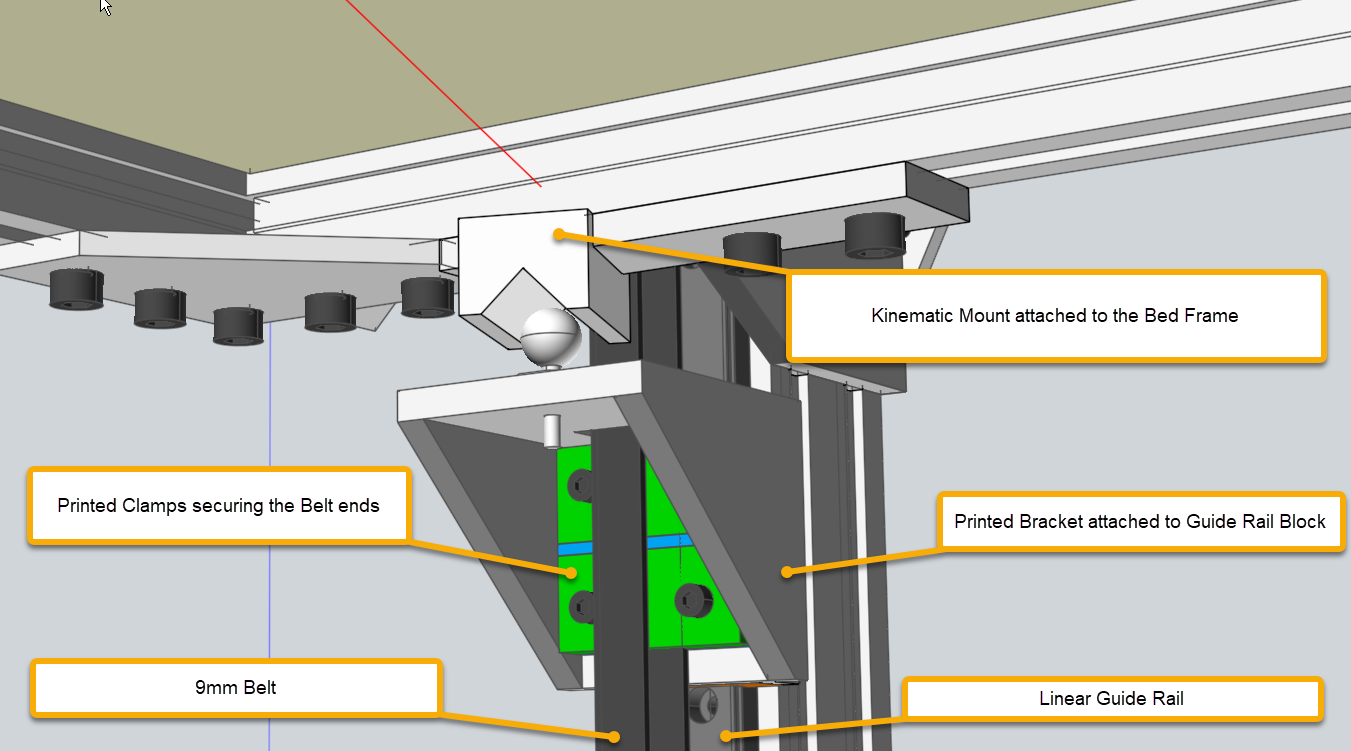
Well on my printers it is done like this. Hope this is enough detail. If not ask for more.
And is a width of 6mm enough, or should I go for 9mm?
I played it safe and used 9mm.
Frederick
-
Thanks for the picture! I had the motor turned 90°, which is not as good as your solution!
About the belt: it belt can be one big closed loop, or a cut part. I have the feeling that a closed loop will be more robust, and less prone to break...
Frédéric
-
I use 2x 9 mm glass core belts to lift the 3.5 kg bed assembly in my printer.
I measured belt stretch using both steel core and glass core belts. The glass core belts (Gates LL2MR09) stretch about 3x the steel core belts, but for the stuff I print, it doesn't matter.See: https://drmrehorst.blogspot.com/2018/12/comparing-steel-core-and-glass-core.html
I had an interesting failure in a belt clamp when I was using steel core belts: https://drmrehorst.blogspot.com/2018/12/another-interesting-3d-printer-failure.html Don't do what I did!
This is the business end of the Z axis- I uses a 30:1 worm gear reducer to turn a shaft with two 60 tooth pulleys that lift the bed assembly.
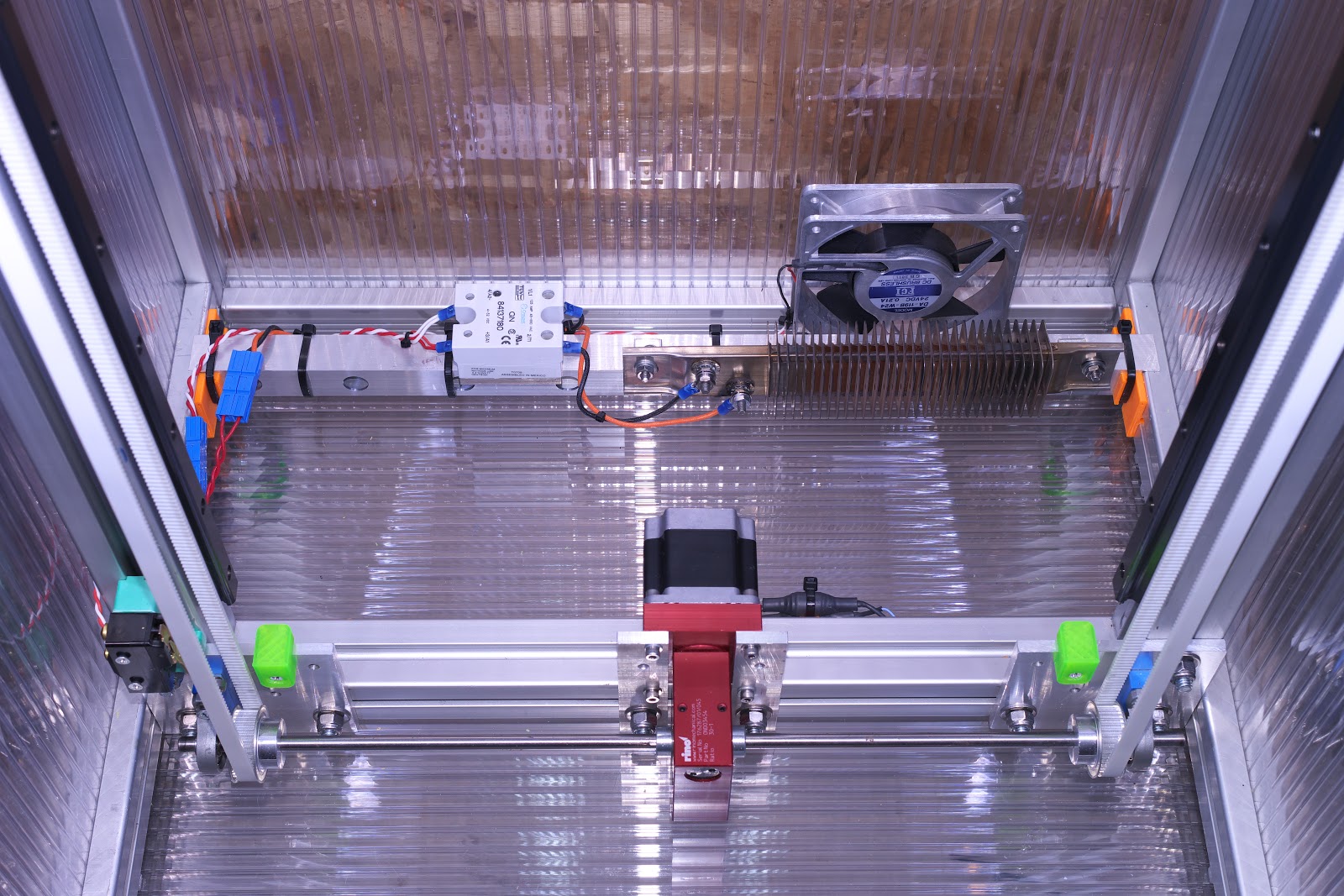
The photo was taken when I was still using steel core belts (before the clamp failure) which have since been swapped for glass core GT2 belts. At the top of the Z axis there are just two pulleys made from stacked F608 skate bearings (which I also used in the XY stage). -
@fma said in slowing down a non-powered stepper motor:
Thanks for the picture! I had the motor turned 90°, which is not as good as your solution!
About the belt: it belt can be one big closed loop, or a cut part. I have the feeling that a closed loop will be more robust, and less prone to break...
The belt looks like a loop since the cut ends are clamped under those green pieces in the drawing which have ridges on the surface you cannot see which match the belt.
The idler pulley at the top, which you cannot see in the image, is adjustable to set belt tension.
Frederick
-
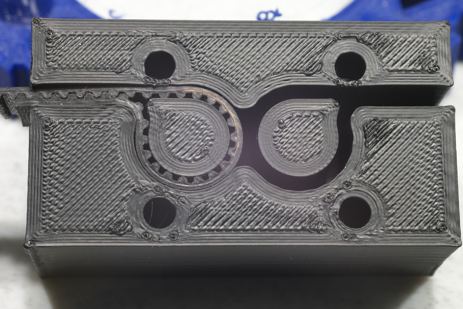
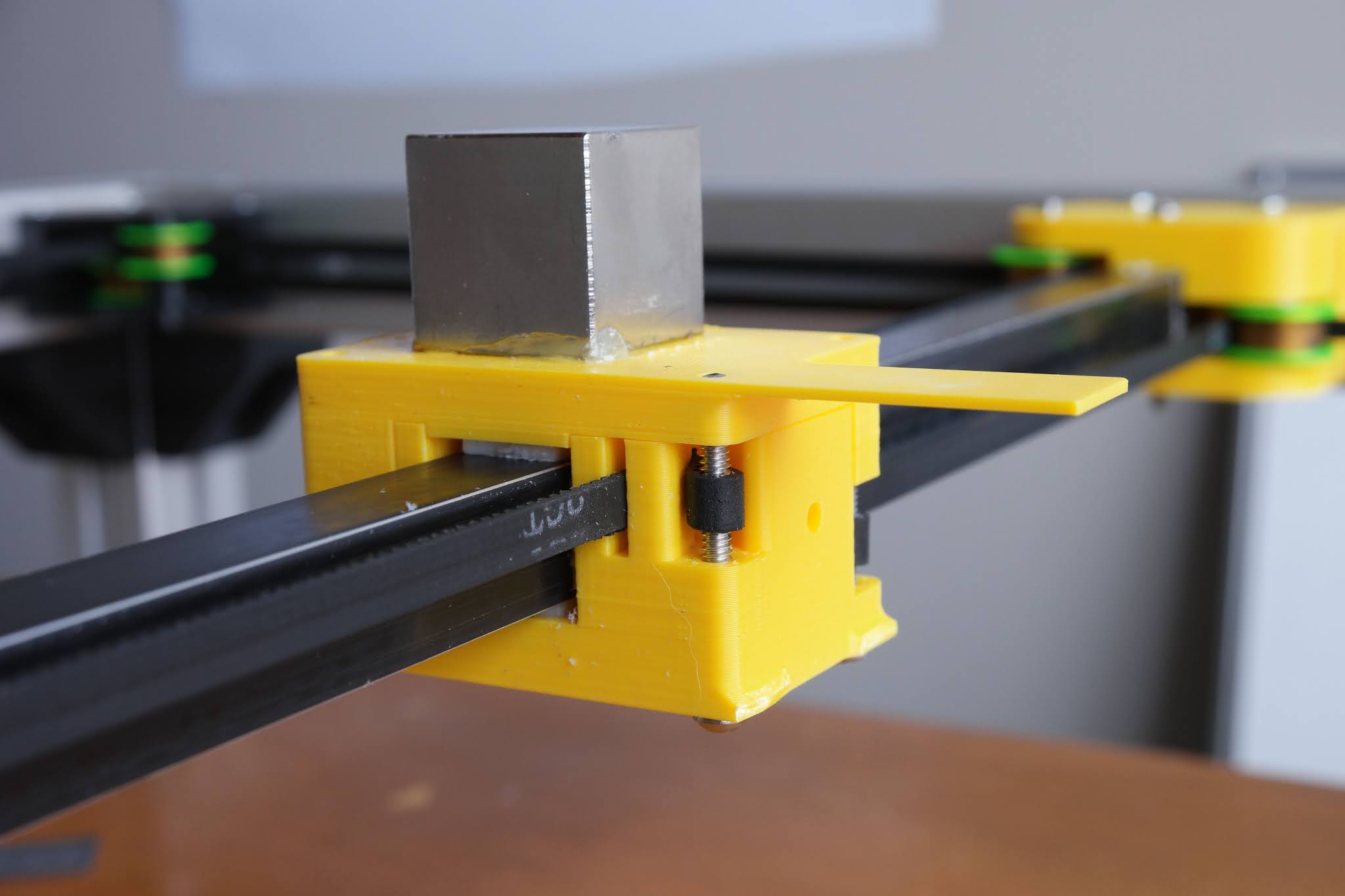
@fma I used open belt formed into a loop by clamping the ends in printed clamps that mount on the Z axis bearing blocks. No closed loop belt is needed. I initially used a simple slot type clamp that failed with steel core belt so I switched to a clamp similar to one I printed and is still working after about 6 or 7 years. You simply fold the belt back on itself and feed the folded part through a slot that keeps the teeth interdigitated. Like this:
The center of the loop in the clamp can be printed (as I did) or it can be the screws that hold the clamp to the bearing block (as was done here) or to a bracket that attaches to the bearing block:
-
Thank you very much for your answers!
-
@fma could also drive you z belt with a worm gearbox. Worm gears can't be back driven.
-
@breed yes, that's mrehorstdmd's solution.