• Tags
  • Documentation
  • Order
  • Register
  • Login
Duet3D Logo Duet3D
  • Tags
  • Documentation
  • Order
  • Register
  • Login

The most helpful post you'll read today

Scheduled Pinned Locked Moved
General Discussion
9
17
1.1k
Loading More Posts
  • Oldest to Newest
  • Newest to Oldest
  • Most Votes
Reply
  • Reply as topic
Log in to reply
This topic has been deleted. Only users with topic management privileges can see it.
  • undefined
    gnydick
    last edited by gnydick 6 Apr 2022, 00:44 4 Jun 2022, 00:43

    After using duet hardware for the last 5 years, I've finally realized that one of the most commonly used instructions is wrong.

    When using multiple Z motors, you use M671 to describe where your lead screws are so the board knows how much to adjust each screw to tram the bed.

    That is wrong. You describe where the pivot point for each screw is. It makes a huge difference.

    So much, that not until now had I EVER had a close to perfect repeat tram.

    To put all potential arguments to bed...

    Imagine your lead screws are 1 km away from your bed in X. You have a 300mm square bed with mounting points 30mm away in X, meaning your brackets are 1km-30mm long.

    Would you tell it that your lead screw offset is 999970mm away in the X direction? No, that would result in literally zero adjustment.

    undefined undefined undefined undefined 4 Replies Last reply 4 Jun 2022, 01:55 Reply Quote -1
    • undefined
      fcwilt @gnydick
      last edited by 4 Jun 2022, 01:55

      @gnydick

      Have you coded for multiple leveling passes until the desired accuracy is reached?

      I think one of the arguments jumped out of bed and is running around outside chasing lightening bugs. Silly argument. 😀

      Frederick

      Printers: a small Utilmaker style, a small CoreXY and a E3D MS/TC setup. Various hotends. Using Duet 3 hardware running 3.4.6

      1 Reply Last reply Reply Quote 0
      • undefined
        zapta @gnydick
        last edited by zapta 6 Apr 2022, 02:56 4 Jun 2022, 02:49

        @gnydick said in The most helpful post you'll read today:

        That is wrong. You describe where the pivot point for each screw is. It makes a huge difference.

        That makes sense. One difficulty I have is how to measure these offsets accurately. I wonder if the firmware could somehow measure them using the bed leveling sensor.

        undefined undefined 2 Replies Last reply 4 Jun 2022, 03:00 Reply Quote 0
        • undefined
          fcwilt @zapta
          last edited by 4 Jun 2022, 03:00

          @zapta said in The most helpful post you'll read today:

          @gnydick said in The most helpful post you'll read today:

          That is wrong. You describe where the pivot point for each screw is. It makes a huge difference.

          That makes sense. One difficulty I have is how to measure these offsets accurately. I wonder if the firmware could somehow measure them using the bed leveling sensor.

          As I recall dc42 said that errors simply slowed the rate of convergence on a solution. But that was a long time ago and my recollection may be wrong.

          I know my triple-Z machine levels fine and I didn't make any special effort to get the dimensions spot on.

          Frederick

          Printers: a small Utilmaker style, a small CoreXY and a E3D MS/TC setup. Various hotends. Using Duet 3 hardware running 3.4.6

          1 Reply Last reply Reply Quote 0
          • undefined
            gloomyandy
            last edited by gloomyandy 6 Apr 2022, 06:21 4 Jun 2022, 06:20

            From the M671 documentation....

            The X and Y coordinates in M671 are measured from the origin X0,Y0 set by M208. Measure to the pivot
            point of the bed where it connects to the Z axis. This is often each leadscrew, but may also be offset from
            the leadscrew if the bed rests on a carriage extending out from the leadscrew.
            undefined 1 Reply Last reply 5 Jun 2022, 00:12 Reply Quote 4
            • undefined
              bubblevisor @gnydick
              last edited by 4 Jun 2022, 14:31

              @gnydick I think your argument is not correct. Leadscrew positions are the pivot points. I don't believe there is a setup where they cannot be. Also your 1km analogy would result in a large leadscrew adjustment, not small.

              undefined undefined 2 Replies Last reply 4 Jun 2022, 16:57 Reply Quote 0
              • undefined
                Phaedrux Moderator @bubblevisor
                last edited by 4 Jun 2022, 16:57

                @bubblevisor said in The most helpful post you'll read today:

                Leadscrew positions are the pivot points.

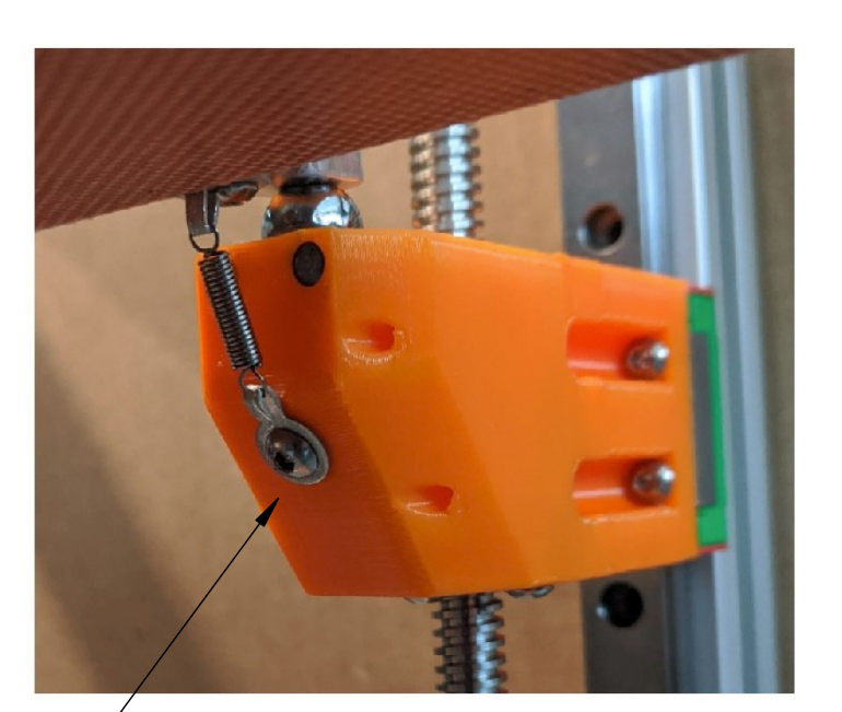
                Only if your bed frame has no built in means of pivoting or flexing to account for misalignment. The frame will flex somewhere, and that's usually going to be in the lead screw nut since there is some slack there. But some printer designs have the pivot point elsewhere.

                For instance the Jubilee printer uses a kinematic mount for the bed.

                c17f05ef-be0a-4f9c-9a1c-ce6eb6dbe1b1-Screen Shot 2022-06-04 at 10.55.55 AM.png Screen Shot 2022-06-04 at 10.55.55 AM.png

                Z-Bot CoreXY Build | Thingiverse Profile

                undefined 1 Reply Last reply 4 Jun 2022, 17:07 Reply Quote 1
                • undefined
                  bubblevisor @Phaedrux
                  last edited by 4 Jun 2022, 17:07

                  @phaedrux Yep. Fair point. I stand corrected.

                  1 Reply Last reply Reply Quote 0
                  • undefined
                    gnydick @gloomyandy
                    last edited by 5 Jun 2022, 00:12

                    @gloomyandy oy, it used to say lead screw 😞 I'm glad it's fixed now!!

                    1 Reply Last reply Reply Quote 0
                    • undefined
                      gnydick @bubblevisor
                      last edited by 5 Jun 2022, 00:40

                      @bubblevisor lead screws.png

                      undefined 1 Reply Last reply 5 Jun 2022, 06:44 Reply Quote 1
                      • undefined
                        gnydick @zapta
                        last edited by 5 Jun 2022, 00:41

                        @zapta I've heard that too, but I don't know how it's supposed to converge if it over-shoots or under-shoots, depending on the inaccuracy.

                        1 Reply Last reply Reply Quote 0
                        • undefined
                          Nuramori @gnydick
                          last edited by 5 Jun 2022, 01:05

                          @gnydick

                          Yep. That’s how I always had it set up. I didn’t realize that’s what was written down differed from that, because I just did what was logical 😛

                          1 Reply Last reply Reply Quote 0
                          • undefined
                            deckingman @gnydick
                            last edited by deckingman 6 May 2022, 06:53 5 Jun 2022, 06:44

                            @gnydick said in The most helpful post you'll read today:

                            @bubblevisor lead screws.png

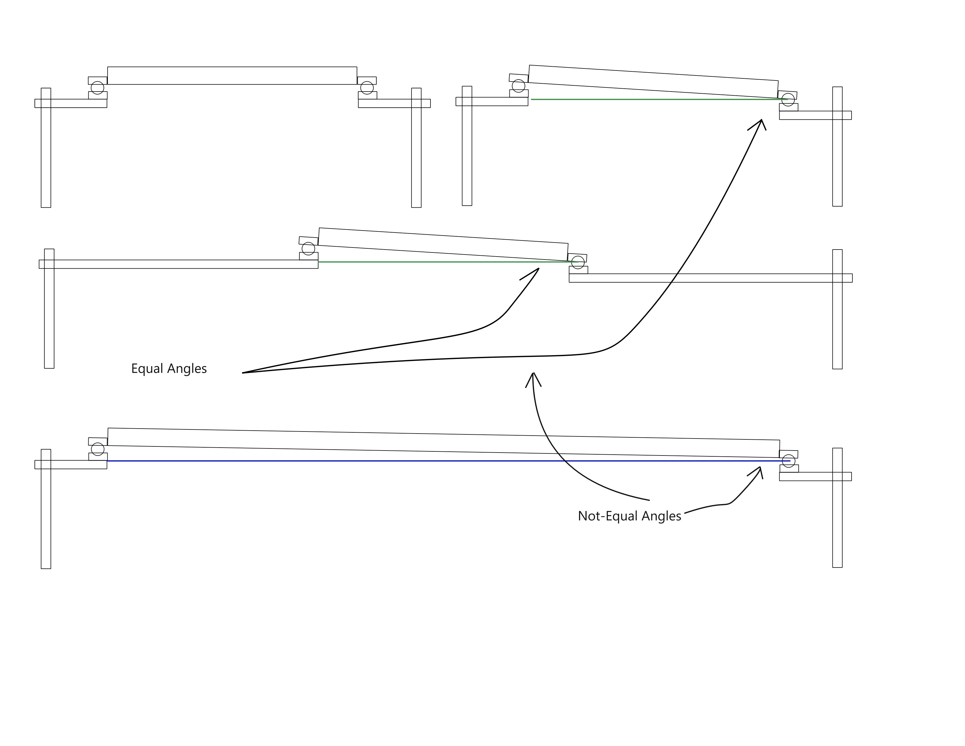
                            I'm trying to get my head around what is being discussed in this thread. But I'm coming from a position where my bed is mechanically flat and level and stays that way, so I don't use any form of firmware compensation myself. But just looking at those images, if the right hand edge of the build plate is low by say 1mm, and the bed is probed on that right hand edge, and those "arms" remain at 90 degrees to the lead screw, then moving the nut on the lead screw up by 1mm will raise the right hand edge of the build plate by 1mm, regardless of the length of the "arm" between the plate and the screw will it not? The only compensation that would be required is the relationship between the probe point and the attachment point if they are not the same. Is that what is being discussed? I don't understand what is being said about pivot point.
                            Edit. The pivot point for the bed is actually the attachment point on the left hand side.

                            Ian
                            https://somei3deas.wordpress.com/
                            https://www.youtube.com/@deckingman

                            undefined 1 Reply Last reply 5 Jun 2022, 17:51 Reply Quote 0
                            • undefined deckingman referenced this topic 5 Jun 2022, 09:59
                            • ?
                              A Former User
                              last edited by A Former User 6 May 2022, 11:33 5 Jun 2022, 11:32

                              This post is deleted!
                              undefined 1 Reply Last reply 5 Jun 2022, 17:45 Reply Quote 1
                              • undefined
                                gnydick @A Former User
                                last edited by 5 Jun 2022, 17:45

                                @arnold_r_clark that's implied, isn't it?

                                ? 1 Reply Last reply 5 Jun 2022, 18:38 Reply Quote 0
                                • undefined
                                  gnydick @deckingman
                                  last edited by 5 Jun 2022, 17:51

                                  @deckingman you're on the right track for the point of the post.

                                  There are multiple pivot points. If you could probe exactly on the pivot points then you wouldn't need to know how far away the pivot points are from the probe points.

                                  But since we are probing at offsets, we need to use trigonometry to figure out how much adjustment at the pivot point will translate to adjustment at the probe points.

                                  1 Reply Last reply Reply Quote 0
                                  • ?
                                    A Former User @gnydick
                                    last edited by 5 Jun 2022, 18:38

                                    This post is deleted!
                                    1 Reply Last reply Reply Quote 1
                                    3 out of 17
                                    • First post
                                      3/17
                                      Last post
                                    Unless otherwise noted, all forum content is licensed under CC-BY-SA