Damn Layer Shift!, time to go Closed Loop?
-
@adamfilip Most layer shifts I've ever seen are caused by some mechanical such as head collision, pulley slipping, build plate moving , belt slipping, or some other such cause. In all such cases, the motor(s) are always reaching their demand position. So closed loop motor control won't help. IMO, the only way to do closed loop positional control is to use a separate linear encoder on the axes to physically measure the gantry positions and compare that with the demand position. Even then, there are scenarios such as the build plate shifting which won't get caught.
I don't think Reprap firmware can take the input from linear encoders and do the necessary comparisons and adjustments for gantry position closed loop control.
-
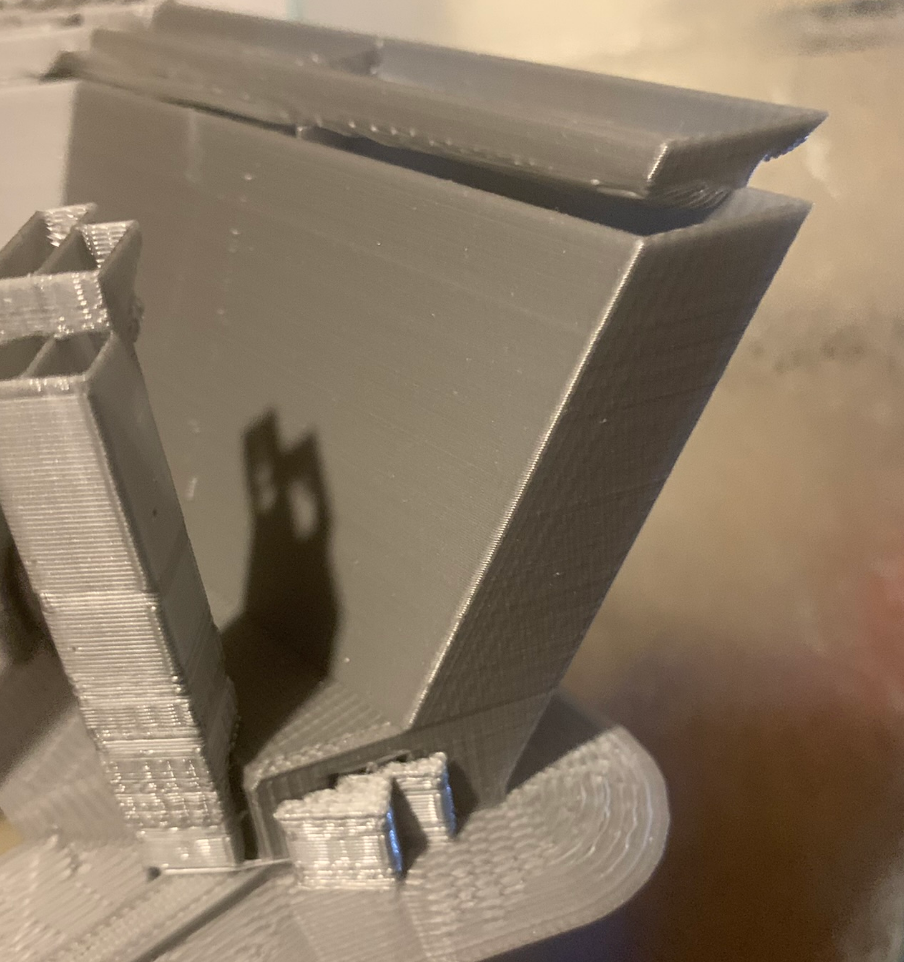
@fcwilt I dont know exactly whats Causing it. but I will assume that its snagging on some support or piece that was printed, which made it miss steps than its screwed. if it was closed loop it should should go back to correct position. and continue on. even if snagged momentarily.
-
@adamfilip said in Damn Layer Shift!, time to go Closed Loop?:
@fcwilt I dont know exactly whats Causing it. but I will assume that its snagging on some support or piece that was printed, which made it miss steps than its screwed. if it was closed loop it should should go back to correct position. and continue on. even if snagged momentarily.
Intersting.
I installed a close-loop setup on one of my printers, just for fun, and it worked fine.
But I haven't had problems like "snagging", so I don't know if it would have corrected itself or not.
In any case, after I tried the setup for a while I went back to open-loop steppers.
I think the first thing you need to need is try to determine the cause of the layer shifting.
deckingman is a bright guy and if he thinks closed-loop wouldn't help he may well be right.
Frederick
-
@adamfilip most likely it was snagging as you say. Increasing motor current and/or reducing travel speed may make the head more likely to ride over the obstruction. Selecting "Avoid crossing perimeters" in the slicer config may avoid the obstruction.
We have the EXP1HCL closed loop driver board in the Duet 3 range.
-
@adamfilip said in Damn Layer Shift!, time to go Closed Loop?:
@fcwilt I dont know exactly whats Causing it. but I will assume that its snagging on some support or piece that was printed, which made it miss steps than its screwed. if it was closed loop it should should go back to correct position. and continue on. even if snagged momentarily.
That's a big assumption to make and could lead to a costly mistake. If you are absolutely sure that the snagging caused the stepper to miss steps and you can categorically rule out all other possibilities such as those that I listed, then a far cheaper option than closed loop stepper motors with built in encoders, would be just to use stepper motors with higher torque.
A cheaper option still would be to eliminate the cause of any snagging, by perhaps tuning your retraction settings or giving the part cooling arrangement some attention.

-
@adamfilip from the looks of the lower layers of this print - its slicer setting and print tuning - not the steppers fault. The poorly formed overhangs, the over extrusion in general. Not sure of the material being used or your slicer settings et al ... but the part of the print that didnt fail doesnt look like its coming off a well tuned printer - ready for a 53 hr challenging print task.
Not sure closed loop servos is the right solution ...
-
@adamfilip FWIW, is it possible that you are using too high a temperature for the filament? If the temperature is too high, although perimeter printing may look fine ( often no retractions ) short line segments with retraction don't work well because the plastic continues to ooze out of the nozzle after the retraction. Just a thought.
-
@sputnikoc3d prior to this print I spent 3 days tuning extrusion, made 30 calibration objects,checking extrusion multipler, checking dimensional accuracy, confirming esteps, and also XY steps, temp towers, Checking wall thickness, checking first layer height, Bits not over extruding. if anything its a hair under extruding.
But thank you for judging that's nice.
-
@dc42 any news on the EXP1HCL when should we expect it in the store?
-
@generisi its running at 210 for PLA+ which is whats generally recommended. temp tower didnt give any indication to lower to raise.
running 0.6 Revo Nozzle. didnt want to go to low either, not worried about a little stringing. I ended up turning on Z hop for my 2nd try and so far so good. no issues after 26hrs.. half way done. hope it finishes -
@adamfilip said in Damn Layer Shift!, time to go Closed Loop?:
But thank you for judging that's nice.
Well that's a super way to respond to someone who is pointing out something that's terribly wrong with your printing system and trying to save you from running around changing from open-loop to closed-loop and all the costs involved only to find you still have a printer performing poorly.
"Thank you, do you have any suggestions on how I can improve the performance of my printer? I'm ready to perform any experiment you think is necessary to help me get my printer working better. " would be a proper response.
But if you know better, just go ahead and spend the money changing everything over to closed-loop and then come back and ask for help once you encounter the same issues or even worse issues.
-
@alankilian I done believe anything is terribly wrong with my printer ? , sure it probably needs some minor adjustment/tweaking. is the print perfect? no. but the actual print is clean, support towers have a rough surface finish (i think thats just the slicer)since the print itself doesn't.
not sure what poorly formed overhangs you are referring too. or are you talking about the shifted part thats overhanging?I wouldn't seriously consider closed loop unless it was affordable. and if it was, why wouldn't i consider it.
PLA+
0.6 Nozzle
0.2 layers
2% infill
2 Permiters
210 degrees
50mm/sec
prusaslicer 2.4Here is the failed print

-
-
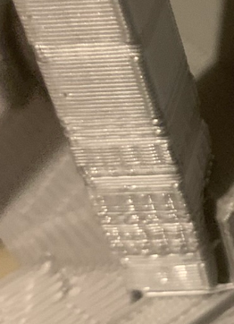
Are you satisfied with how the outer wall of this part of the print varies far from smooth?

It looks pretty nonuniform compared to prints that come off my printer.
I think taking some time printing square or round towers along with other objects on the same build plate will help you understand how your printer is misbehaving and how to improve its print quality.
until you do that and can get quality prints imagining closed-loop control is a waste of time.
Just as an example, here's a print of part of a rocket nozzle I printed using my Duet2.

See how uniform the print is along the Z axis compared to how nonuniform your print is? That's the result of weeks of tuning the slicer settings. (Well, I have to admit I couldn't get the slicer to do a good enough job, so I wrote a program in C to directly generate GCODE to perform the moved to create this print, but I don't expect you do to that.)
Try getting your printer to produce nice smooth walls on your print and then if you absolutely cannot get it to do so, consider going to closed-loop.
If you don't do all the hard work first, you will never get good prints and will always be blaming something else.
-
@fcwilt to reduce the permiter count down from 3 to 2 with similar wall thickness
-
@alankilian the non uniform part is a support tower, I am not sure why but the support towers tend to looks less smooth than the actual part they are supporting
-
@alankilian that’s a clean print for sure. Was that in vase mode? What speed and layer heights was that done, just curious
-
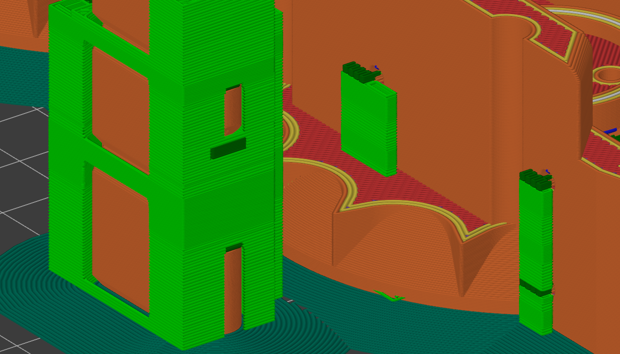
@alankilian even in prusaslicer preview the supports have a rough non uniform appearance.

-
@adamfilip said in Damn Layer Shift!, time to go Closed Loop?:
@fcwilt to reduce the permiter count down from 3 to 2 with similar wall thickness
Thanks.
Frederick
-
Looking at your example, there are two areas that imply some additional tuning may be required -- if not for this print, then maybe for future ones.

In A, there seems to be roughness on short infill, which may be an indication that it's worth tuning retracts and PA a tiny bit more.
In B we see kind of a line, which is similar to the infamous Benchy Hull Line which appears where the plastic cools down differently due to a geometry change such as in your part. B is very difficult to tune out completely, and your filament is an excellent choice to point out any and all flaws that may not even be as visible or even relevant in the real world. If the transition point feels smooth, it's probably fine to ignore.
Especially A could lead to either the nozzle or a low mounted Z probe snagging on filament that curled up. B just indicates that tuning for overhangs/and or part cooling might improve the print overall.
If your current printer setup does not allow for more cooling, printing slower may be an option. Sometimes it's surprising how well reducing terminal speeds by 30 to 50 percent helps without adding more than 10 to 20 percent to the print time (since jerk and acceleration affect overall print time considerably). I understand that this may be undesirable on a multi day print, but it's still better than having to have multiple attempts. Printing slower also means more uniform printing which leads to more a) uniform surface finish, which may or may not be relevant depending on whether you plan to fill/sand/paint the part or not and b) better interlayer adhesion.