Issues with pressure advance since RRF 3.4
-
@Argo
I have a Duet 3 6hc running on Klipper. But I can't test it because otherwise I would have to lay 13 cables to the print head and unfortunately I don't have the time to do so. -
I've found a work around for the issue.
Super slicer has this fancy feature called "Between extrusion role change G-Code".
So I've added the following code for PLA:
{if extrusion_role=~/ExternalPerimeter/};[extrusion_role]                   ;  ExternalPerimeter
M572 D0 S0.080 ; Pressure Advance
{elsif extrusion_role=~/Perimeter/};[extrusion_role]                        ;  Perimeter
M572 D0 S0.080 ; Pressure Advance
{elsif extrusion_role=~/OverhangPerimeter/};[extrusion_role]                ;  OverhangPerimeter
M572 D0 S0.080 ; Pressure Advance
{elsif extrusion_role=~/InternalInfill/};[extrusion_role]                   ;  InternalInfill
M572 D0 S0.05 ; Pressure Advance
{elsif extrusion_role=~/TopSolidInfill/};[extrusion_role]                   ;  TopSolidInfill
M572 D0 S0.05 ; Pressure Advance
{elsif extrusion_role=~/SolidInfill/};[extrusion_role]                      ;  SolidInfill
M572 D0 S0.05 ; Pressure Advance
{elsif extrusion_role=~/BridgeInfill/};[extrusion_role]                     ;  BridgeInfill
M572 D0 S0.05 ; Pressure Advance
{elsif extrusion_role=~/GapFill/};[extrusion_role]                     ;  GapFill
M572 D0 S0.05 ; Pressure Advance
{elsif extrusion_role=~/Skirt/};[extrusion_role]                     ;  Skirt
M572 D0 S0.05 ; Pressure Advance
{elsif extrusion_role=~/SupportMaterial/};[extrusion_role]                     ;  SupportMaterial
M572 D0 S0.05 ; Pressure Advance
{elsif extrusion_role=~/SupportMaterialInterface/};[extrusion_role]                     ;  SupportMaterialInterface
M572 D0 S0.05 ; Pressure Advance
{elsif extrusion_role=~/ThinWall/};[extrusion_role]                     ;  ThinWall
M572 D0 S0.05 ; Pressure Advance
{else};[extrusion_role]                     ;  Unknown generic handling
M572 D0 S0.05 ; Pressure Advance
{endif}
Result are strong infill and sharper corners.
The "solution" feels like a hammer though
But at least I can use the printer again for functional parts. -
@Argo That's interesting. So basically you are using a different PA value for perimeters to everything else? Do you have a picture of a part using this?
Hmm just a thought is the speed or acceleration used for perimeters different to the rest of the model?
-
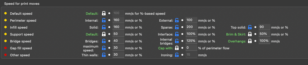
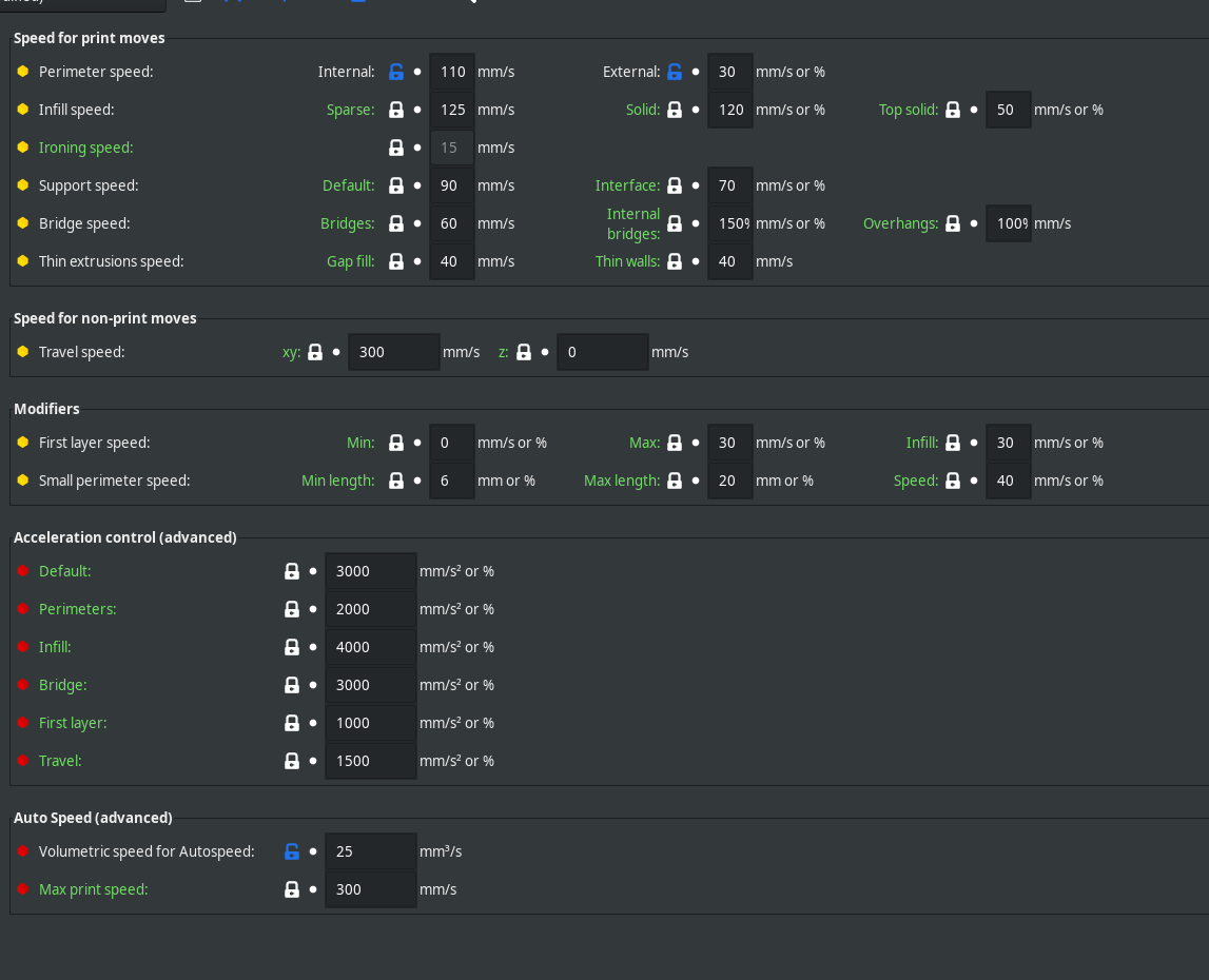
Speeds
Acceleration
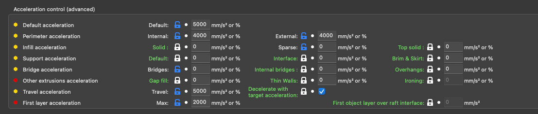
For testing purposes I already tried printing everything with one speed and acceleration setting. I really tried almost everything to find out what's wrong

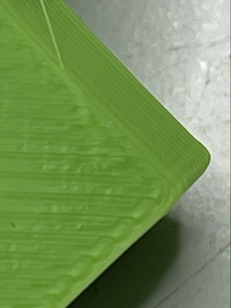
Somewhere in this thread I did also post some examples of prints with too much PA which ended up in incomplete infill lines but nicer corners.Here is the result with the extrusion role gcode:
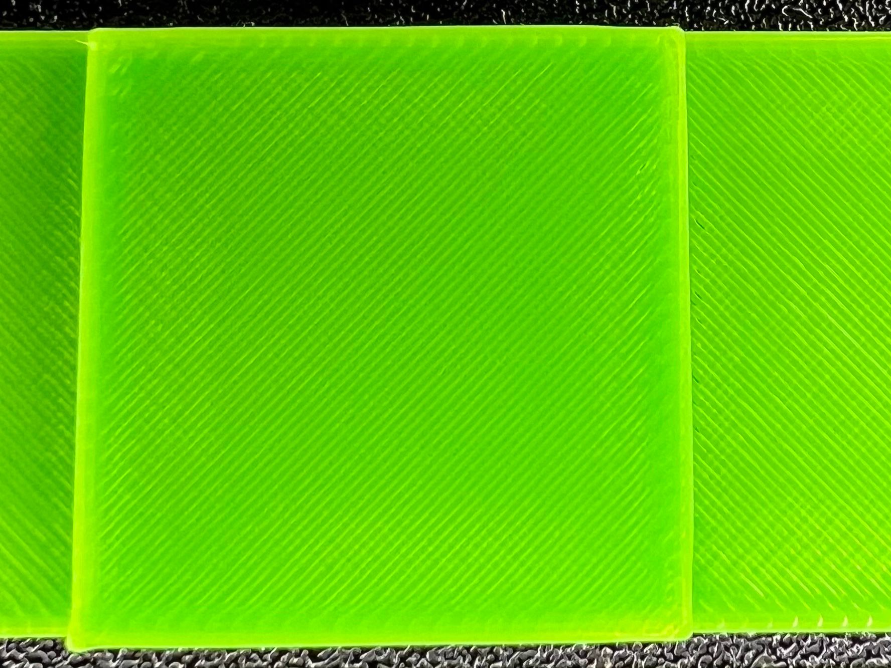
It's still far from perfect. The bottom left corner is still bulging. I think it's because it takes a short bit of time until the gcode is processed (buffer maybe?). The bottom left corner is always the starting point after the infill is being printed. The other corners are somewhat ok.
For the example I used PA of 0.05 for everything except perimeter which used PA of 0.09. Quite the difference... -
@Argo I was wondering if perhaps there might be some scope for speed or (given how you have things set) acceleration based PA... So basically allowing the firmware to dynamically vary the PA settings based upon some other element of the print process...
In respect of that lower left corner does adding M400 before the PA change for perimeters help?
-
Good idea, I’ll try the M400 command tomorrow.
As for acceleration based PA. Does this maybe relate to the issue?
https://forum.duet3d.com/topic/28533/pressure-advance-and-variable-flow-ratio -
I could only find out with firmware 3.3.0 that, for example, my Z-axis ran softer with the same jerk and ACC and not as hard as with 3.4.x Maybe you should look in the direction of the braking behavior? If I get it in time I will flash my Z axis again to 3.3.0 and then film it again with 3.4.x.
-
Unfortunately M400 does not help.
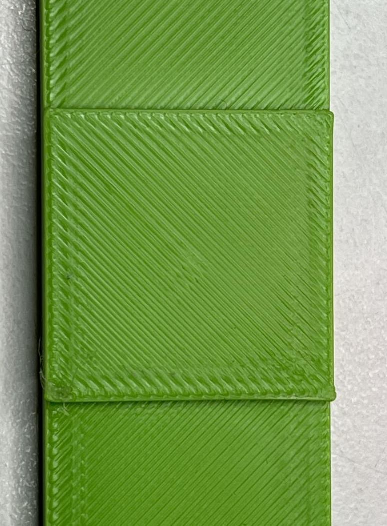
I also found a another issues that comes with high PA values for external perimeter:
The marked area is where the seam is. This is expected with a PA value of 0.08 - 0.09 but needed for nice sharp corners.
Result with PA 0.05 (everything except perimeter) and PA 0.085 for perimeter with M400 usage. Bottom left corner is still bulging:

At least we see now what effect pressure advance has with different settings at the same printed object.
Maybe a post processing script might improve the quality even further with a logic that analyzes the gcode file for sharp corners so that the high PA value isn’t used for all perimeter segments (to prevent defects at round sections) but only for sharp corners. -
I can confirm that this flaw does exist in 3.4:
-
@Chriss Do you have an example of a setup that does not have this overshoot? So for instance are you saying that you did not have the problem with 3.3 (with all other settings the same)?
-
@gloomyandy Well, what can I say here? It was fine with 3.3 back than. I printed enough test cubes etc.
I print mostly technical parts. This overshooted corners are na no go with them.
-
Here pic from a 90° corner with rrf 3.3:
(Yes PA was not very well tuned, but you get an idea) -
@Chriss So the real test is to switch back to 3.3 change nothing and see if you get the same results, I realise this is a pain to do, but so far we have not been able to identify an example of a change between 3.3 and 3.4...
-
@Chriss Oh and if you do run this test, you may need to disable any input shaping you have added in 3.4, I'm not sure what having a 3.4 input shaping command will do to a 3.3 setup... The goal is to have two prints one with 3.3 one with 3.4 using identical config.g and identical gcode files, one has the problem the other does not. That will hopefully give others things to work with to identify the problem...
-
@gloomyandy if you don't have 3.3 try a higher Z jerk and acc. flash 3.4 and the axis runs much more aggressively. could this also be the case for x and y?
-
@Heartleander81 If you think there has been a change between how Z jerk and acceleration works in 3.3 and 3.4, then I think you should probably create a new thread to discuss that. Are you using CAN boards for your Z axis?
-
Just for science. I made a huge cable mess with my printer as I flashed the machine to Klipper with a BTT toolboard and Duet 3 Mini as mainboard.
I did not really fine tune the printer so the flow is a little bit too high as you can see but the pressure advance was set to 0.05. Maybe 0.053 would be even better as the corners could use a tiny bit more BUT I don't have to use the extrusion role feature to print perimeter with 0.08 pressure advance.
Result with PA 0.05 (Klipper, same machine) without much tuning.

At least now I know it's not the machine...
Time to tidy up the machine again as this was only a test with all cables just clipped to the tool board
-
@Argo Flipper on a RRF board is a kind of a disgrace.
")
-
@Argo Well there certainly seems to be a bulge on the top right corner in that test print. It also looks like you are using a different filament.... Is this using the same gcode as the RRF case becuase the seam looks like it may be in the bottom right corner, I thought it was in a different place in the RRF prints?
Unfortunately I don't think you can run RRF with the same hardware setup, so again it is going to be hard to compare like for like....
-
Bottom left and top right have a small bulge.
PA was set to 0.05 which is a little bit too low. For RRF I need 0.08 to get similar results and the SuSl feature to switch between PA values whilst printing because PA 0.08 would cause defects all over the place which I'm still getting.The hardware / printer was the same except for the tool board. Unfortunately Klipper can't communicate with the 1LC that's why I had to make a mess in my room and needed 2m of cables or so to wire up the BTT tool board.
I just wanted to rule out a hardware issue and show that is has to be somehow software related.Things we tried or can rule out:
- extruder (I tried LGX and LDO Orbiter 2.0)
- tool board (someone tried with and without in this thread)
- nozzle (I switched from Bondtech CHT to E3D V6)
- stepper motors (I switched the motor when switching from LGX to Orbiter 2.0)
- RRF 3.3 and RRF3.4 (same results for me and others)
I have another printer (bed slinger) that's also running a Duet 3 Mini with RRF 3.4. This printer has no issues with bulging corners.
Could it be a issue with the CoreXY logic RRF uses?