Pattern Pressure Advance Calibration
-
For the last few weeks, there has been a new method of calibrating pressure advance with klipper called the pattern method. This is now the recommended method to use over the lines method.
As of a few minutes ago, the online generator now has RRF support too.
The pattern PA calibration generator can be found here https://ellis3dp.com/Pressure_Linear_Advance_Tool/ and the information about how to interpret it can be found here https://ellis3dp.com/Print-Tuning-Guide/articles/pressure_linear_advance/introduction.html
Owns various duet boards and is the main wiki maintainer for the Teamgloomy LPC/STM32 port of RRF. Assume I'm running whatever the latest beta/stable build is
-


-
@Alex9779 well done Alex for putting in the work. Didn't realize you were here
Owns various duet boards and is the main wiki maintainer for the Teamgloomy LPC/STM32 port of RRF. Assume I'm running whatever the latest beta/stable build is
-
@jay_s_uk I saw you also started a PR, did you begin before I created mine? Sorry if you put some work into it and mine got merged but really appreciated your comments and directions, remembering all the stuff spread around the config files is hard if you don't do it on an everyday basis and just use the machine...
-
@jay_s_uk said in Pattern Pressure Advance Calibration:
Didn't realize you were here
I have been around since E3D published their BigBox and I switched to a Duet board for it...
-
@Alex9779 I hadn't noticed your PR. Doesn't matter though as yours was more elegant than mine anyway. Plus I need to coding practice.
Next up is adding RRF commands to Andrews guide where required. -
@jay_s_uk
like it, his guide is so good, I got so good initial results after I built my Voron just by adapting his profiles.
I hope his PA calibration will spread, with that generator it is so much easier to do.
Maybe someone can put that into the Duet docs too? https://docs.duet3d.com/en/User_manual/Tuning/Pressure_advance -
@droftarts is the man to add it to the docs
-
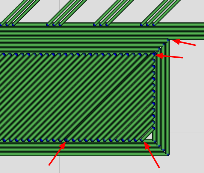
Is anyone else seeing an over extrusion in the label area infill?
My perimeters and test lines are extruding perfectly. But that small pane of solid significantly over-extrudes the infill.
I double checked and compared to the perimeters, the line spacing and extrusion rates match. My best guess is that there is too much overlap between infill and perimeters.
:edit:
That seems to be the issue. And possibly a doubled up infill line as well. Plus too much overlap with the perimeter of the main anchor:
I'm also wondering why the test lines seem under-extruded on the first layer. Are they being extruded at a rate for the nominal layer thickness, not the first layer thickness?
-
@CCS86
Hey guys.- The first layer can look a bit overextruded partly because it uses your starting PA (often 0).
- The infill/perimeter overlap should be 25% but I will verify that is working properly
- The doubled-up infill line is a bug I just fixed today actually, will be pushing that up soon
- The extra overlap for the number tab is on purpose, but even with that extra overlap I'm seeing people with the tab not sticking, hah. It was meant to help it be more likely to stick for folks whose squish isn't quite enough. Ideally it would slice it all as one object rather than two rectangles overlapping, but coding is hard, so just two rectangles for now, heh.
- I'll also check the extrusion rates for first layer vs other layers
-
@Ellis said in Pattern Pressure Advance Calibration:
@CCS86
Hey guys.- The first layer can look a bit overextruded partly because it uses your starting PA (often 0).
- The infill/perimeter overlap should be 25% but I will verify that is working properly
- The doubled-up infill line is a bug I just fixed today actually, will be pushing that up soon
- The extra overlap for the number tab is on purpose, but even with that extra overlap I'm seeing people with the tab not sticking, hah. It was meant to help it be more likely to stick for folks whose squish isn't quite enough. Ideally it would slice it all as one object rather than two rectangles overlapping, but coding is hard, so just two rectangles for now, heh.
- I'll also check the extrusion rates for first layer vs other layers
Maybe you could add a parameter that people could use to assist in first layer adhesion.
I have mine dialed in and don't need the extra overlap:

You can see that my first attempt had great perimeter extrusion, very over-extruded in the tab, and under-extrusion on the test lines.
-
@CCS86 I don't think it's worth adding more setting clutter for the tab overlap. It's not causing any actual issues, is it?
The tab isn't usually that bad. When I said it looks a little overextruded, I meant more like this:
https://photos.app.goo.gl/4HSMCC2aQ2mmb7pWAI think something else may be contributing there. Your pattern ends are very blobby at 0 PA so that's likely also reflecting in the tab. And the perimeters there don't show minor over-squish nearly as much as the tab does
140% default anchor line width is also fairly fat, which may contribute
For now try the anchor layer rather than the anchor frame to get the patterns to stick - I will look at first layer flow there later today
Also please share your gcode file
-
Here is the gcode file:
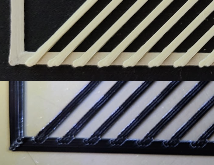
I am using 118% for both line widths, and a 0.25mm first layer height in that photo.
My pattern ends at PA0 look less blobby than your IMO, but my tab is more over-extruded:
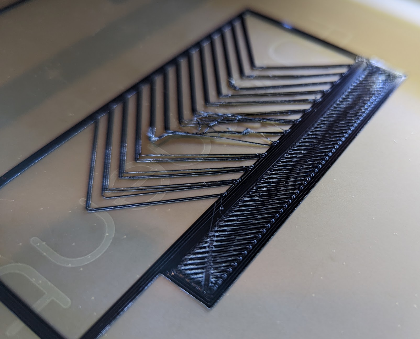
I think it's an issue. Even a 0.1mm Z hop can't clear it, and you can see the nozzle has smeared right through a lot of plastic. Overpressuring the nozzle and smearing through extra plastic isn't the best way to start a precision calibration. There are like 43 settings in the script. If adding 1 more can prevent such bad over-extrusion, that seems well worth it to me.
-
I've been running some tests using this pattern on my printer with a 1mm nozzle. I set all line widths to 1mm and everything sticks fine (230C PETG at 30 mm/sec on 70C PEI).
I'm not entirely sure what I should be looking for in the resulting print- the corners should be sharp and not blobby or gapped, but should I also be looking at the ends of the test lines that print on the anchoring border, or is that more of a retraction tuning issue? I am using the default 0.5 mm retraction...
My initial test with the PA at the default range had all the test corners looking identical. I tried again going from 0.1 to 0.5 and finally started to see some gaps in the corners.
-
@CCS86
Yes, but you are comparing 30mm/s first layer to my 150mm/s top layers
My bottom layers are not as blobby, though you can't see it in that photo -
@mrehorstdmd Did you see the guide link up top, next to the 3d preview? Has an example in there showing what to look for
-
@CCS86 Also just to be clear, I don't mean to hand wave your issues here, just comparing with others
- I think the overlap is too much in places as you said, that spot included, so I may reduce that.
- Maybe it should also just print the first layer at your current PA, and not set PA until second layer+? Might also help
- I am wondering if the overextrusion would be less with 120% first layer width, maybe the default of 140% is just a bit aggressive.
- I have pushed a fix for the doubling-up infill line, at least I think so, can you please see if it's still occurring for you?
- I think I see a flow issue with the first layer of the pattern itself (not the perims/anchor/tab), working on that bit. Thanks for spotting that. Not 100% sure yet, though, so I'll update here soon
- I think the overlap is too much in places as you said, that spot included, so I may reduce that.
-
@mrehorstdmd I am curious to see some photos with 1mm nozzle, largest nozzle I have seen used so far is 0.8mm
-
@Ellis I'll print some new tests tonight and shoot some photos and post them. The 1 mm nozzle has been a b**** to print with for everything except single wall vases for a long time. I suspect there's not a lot of pressure in the hot end, and the viscosity of the molten filament probably has less effect on extrusion.
-
@mrehorstdmd Found some small errors in the flow math, hold off for now