HELP! Same gcode but different size prints are being produced
-
I started printing this large shell and tube heat exchanger, but I am running into a big problem.
I sliced with simply3d and uploaded to my duet 3 main board 6xd running an older version 3.2.0. The cap to the heat exchanger is supposed to be 420mm and I got 1 print in petg that is the correct size. I also printed the shell which is the correct size as the file. But I printed a second cap which came out to 414-415mm so its ~6mm smaller that what its supposed to be. So I printed another shell which came out smaller than my previous shell. I then printed a second cap and its back to the correct size of 420mm. So now the correct size parts push fit with other normal parts and the smaller parts push fit perfectly with the other smaller parts. Im using a big delta printer the height is correct on all parts but its just the width that comes out wrong sometimes. I am using the same gcode that was uploaded to the duet. One day its a normal print, the next day its smaller. 2 different parts/file same result.
I thought a lot before posting this and the only thing I can think of is how the duet is controlling the printer. I am using a heated chamber around 45c on a 75c bed. So I thought about thermal expansion on it cooling down in the camber slowly vs me taking it out right away when its finished. Thought about maybe its the g10 I am printing on contracting but its screwed down and I tried both removing the part right away vs leaving it cool down slowly on the bed. The part does not lift off the bed at all. Zero warp! It is perfect. I am using a smart effector so first layer is perfect. It can't be my arms, Pullys, or motors because the nozzle would eventually run into the part and destroy itself like it has in the past. I am getting perfect looking prints.
Is it possible its duet related? I don't see how the gcode would do that. Each shell I print is 3.5 rolls of filament and each cap is 1.5 rolls. So these errors are costly. I will prob update duet web but wanted to see what you guys think?
-
@patterson6 The error is only 1.2%. Most prints are OK with that. But in your case it scales up.
I can only guess, it's caused by repeatability of calibration / SmartEffector / Zmax-endstops.
Also the chamber temp when calibrating should be the same every time. Effector-rods expand, too.
Just a little bit of dirt under the nozzle while calibrating can mess up the result. It's recomended to heat up the nozzle and wipe it before calibration. -
@o_lampe I wipe the nozzle every time and even wire brush it. First layer is perfect. Height map is decent. Effector rods are 10mm pultruded cf with delrin ends. I hear what your saying but something is wrong. I say that because I can see the imprint on the G10 that is even smaller vs the normal size. G10 is on a thick aluminum mic6 that is even screwed down to the aluminum. I am even using thicker G10 than most people that is 2+mm thick. It seems flush during the whole print and really grabs onto the petg. Even my rostock frame is bolted down to the top and bottom of the encloser. It really seems like the duet is altering the steps wrong sometimes on different prints but the same gcode.
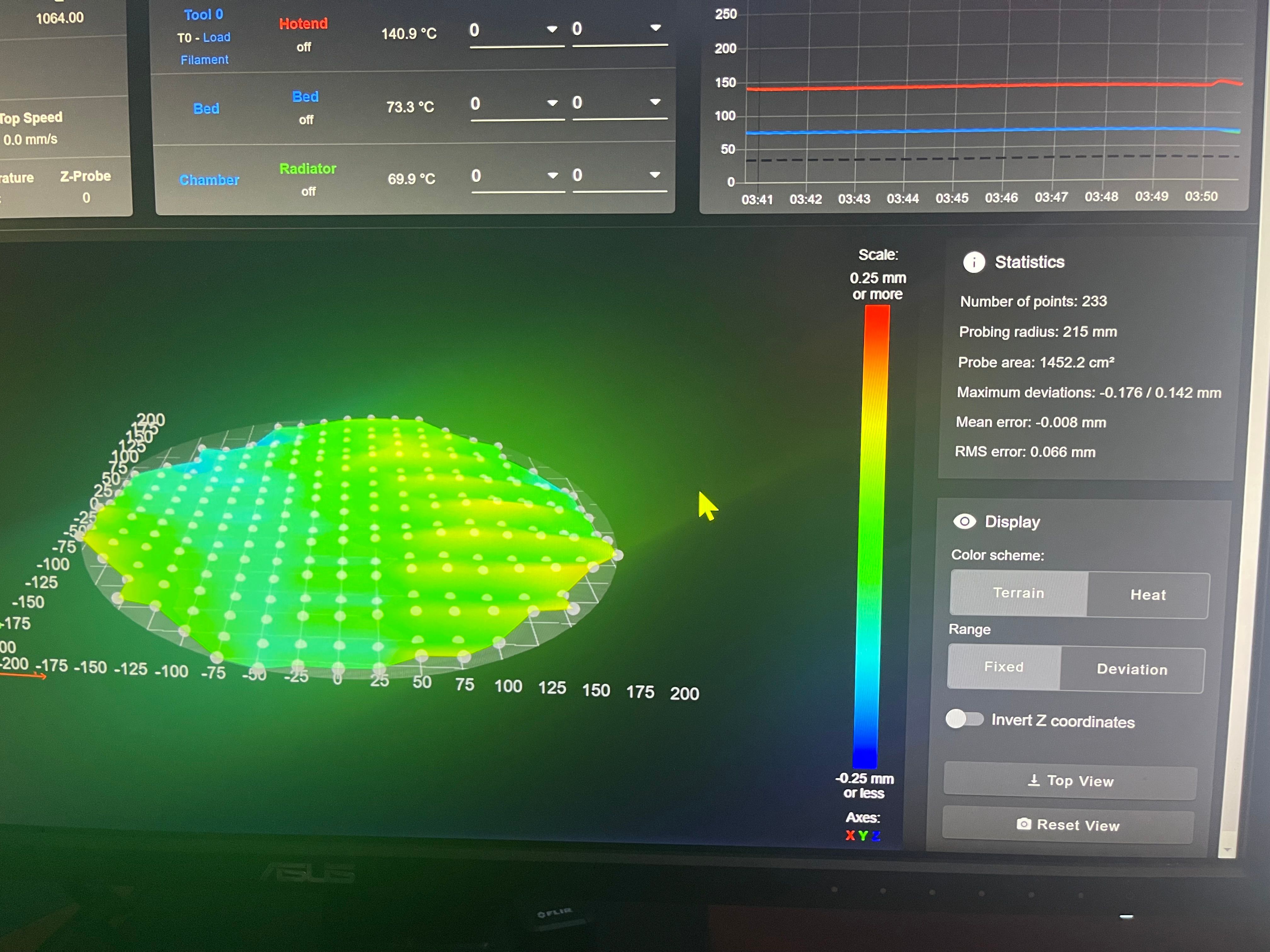
233 points probed, min error -0.286, max error 0.283, mean 0.013, deviation 0.094... That was for the endcap that printed to the correct size.
Would I be better off in this scenario and not run g32 and g29 each time? I am using a 1.2mm nozzle.
I actually have a video on it if you need to see the printer. I did change to g10 after I made the video. https://youtu.be/5jfJOEAGewI
-
@patterson6 said in HELP! Same gcode but different size prints are being produced:
.................................. Would I be better off in this scenario and not run g32 and g29 each time? I am using a 1.2mm nozzle.
I'd say probably yes - or at least, give it a try. I know next to nothing about Deltas but given that you have variation in print sizes and the gcode file is fixed, then logic would dictate that there is some other variable at work. Are these prints are all with the exact same filament and all other settings such as temperature and part cooling are the same from print to print? Is the ambient temperature stable between prints? That might affect shrinkage. Essentially, the gcode file is fixed so one needs to find some other variable.
-
@deckingman heated chamber and bed are the same temps on all prints. Does not matter if I take the part out right away or let it cool to ambient room temperature hours later. One 420mm cap was taken out right away and one 420mm cap was cooled to room temperature and same exact size.
I did do a different brand of filament on the 2nd printed cap that resulted in the smaller 414mm size. I later found it to be not the problem either. First cap was printed in deramic petg and got 420mm. Second cap was first 5ish layers with deramic then finished with overture. So at this point I thought it was the brand or material. So then I printed the 3rd cap with overture and got 420mm which killed that theory. So one dermaic and one overture and both ended up being true to file size. Same color black.
It really seems like the first layer is even scaled down to 1.2% smaller on the 414mm size. The part while being printed is 100% stuck to the bed. Almost to good to where if I use alcohol I cant get it off. I have to use windex. No warp, no lifting. The smaller part is consistent at the top to the bottom in 1.2% reduction on the width. To me it really just seems like the duet is changing the parameters on the width.
1.2% is a huge problem with this print. Some parts bolt together and then the cap is push fit to the shell. Neither the bolts or the push fit come even close to fitting. The normal size cap fits perfectly with the normal shell, then the smaller cap fits perfectly with the smaller printed shell. Its like I have to keep printing and get lucky to what size I'm going to get or end up with two versions. A 420mm shell and tube and a 414mm shell and tube.
I am planning on printing an even bigger delta in the far future with a 600mm bed and 1500mm build height but this 1.2% needs to be figured out. A 600mm bed with 1.2% reduction is 7.2mm smaller.
-
@patterson6 said in HELP! Same gcode but different size prints are being produced:
Would I be better off in this scenario and not run g32 and g29 each time? I am using a 1.2mm nozzle.
You could test the calibration with a dummy print before doing the 3 day job. If it comes out right, use M500 to store the delta-calibration.
Next time you calibrate, the before and after-values of the calibration should be close or even identic.
If they're far off, repeat the calibration.
I usually home the printer twice before calibrating and do mesh-probing only after I changed something around the printer.BTW: Just out off curiosity. Isn't there a better way to (mass-) produce these things? FDM printers are good for rapid prototyping or one-off things.
I recently wrapped my head around moulding and 2k epoxy resin. Maybe that's the solution for your small series production, too?
Just my 2 cents... -
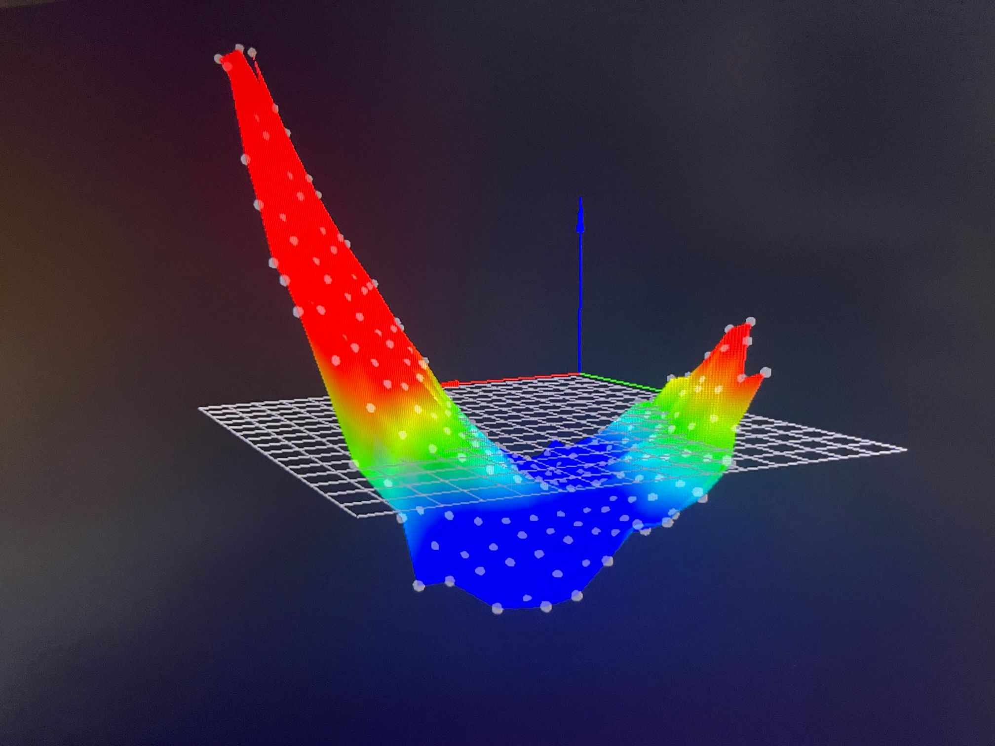
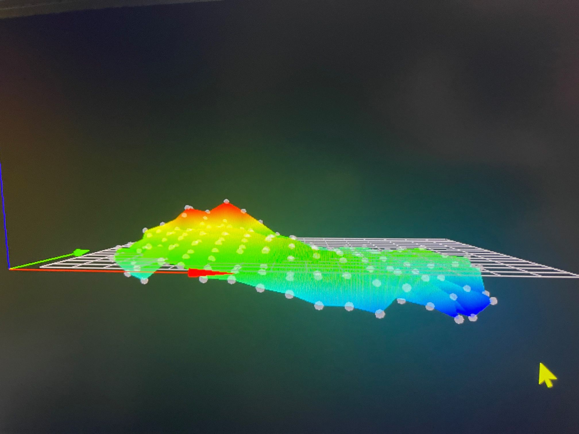
So I started printing another part that bolts to the endcap and I'm getting the same results. So that's three different files giving the same results of errors. I Then just started printing the first layer and seeing how the holes for the bolts line up. I observed every other print is giving me the small width then it would go back to normal. It is height map related and here are my results. What would cause this to go back and forth giving me a decent height map then a really bad one. Does not matter if the printer is warmed up to the desired print temp and then started or just sat warming up for 30 mins. I am still using the old version 3.2.0. updating that is my next step when I get more time this weekend. look how consistent the max deviation is every other attempt to print using the same gcode.
Probing radius: 215 mm
Probe area: 1452.2 cm²
Maximum deviations: -0.396 / 1.690 mm
Mean error: 0.103 mm
RMS error: 0.472 mm
result is small width
printed right when warmed upNumber of points: 233
Probing radius: 215 mm
Probe area: 1452.2 cm²
Maximum deviations: -0.163 / 0.262 mm
Mean error: 0.043 mm
RMS error: 0.063 mm
result is normal width
printed 30min after warmed upNumber of points: 233
Probing radius: 215 mm
Probe area: 1452.2 cm²
Maximum deviations: -0.339 / 1.737 mm
Mean error: 0.153 mm
RMS error: 0.465 mm
result is small width
printed 60min after warmed upNumber of points: 233
Probing radius: 215 mm
Probe area: 1452.2 cm²
Maximum deviations: -0.283 / 0.244 mm
Mean error: -0.067 mm
RMS error: 0.125 mm
result is normal width
printed 60 min after warmed upNumber of points: 233
Probing radius: 215 mm
Probe area: 1452.2 cm²
Maximum deviations: -0.482 / 1.608 mm
Mean error: 0.093 mm
RMS error: 0.461 mm
result is small width
printed 60 mins after warmed up -
U shape height map gives small width size

Normal height map gives normal print size

So the U shape height map seems new. I still get decent first layers on both height maps. Using a 1.2 mm nozzle is prob why. I have had this printer for a while now and never really seen a map that bad. What I changed to my printer recently was the g10 bed on top of the mic6. Normally I used Printbite. Had to replace the smart effector so now I have the new version on with the small JST PH connector that I hate. I also replaced the carriages with a 3d printed design of mine. New belts.
The fact that the height map is every other is what's blowing my mind and I cant figure out. U shape then normal. U Shape then normal. Everything I listed above that I changed is a fixed position. Could it be the smart effector?
-
Take a look here to help interpret your heightmap.
-
@patterson6 Can you post your sys/bed.g file? This is what is run when you send G32. Are you running G32 between each G29 (mesh bed levelling)? My guess is that there's an error in bed.g that is causing this.
Ian
-
BED.G
; generated by RepRapFirmware Configuration Tool v3.2.3 on Sun Feb 28 2021 07:03:53 GMT-0600 (Central Standard Time)
M561 ; clear any bed transform
; bed.g file for RepRapFirmware, generated by Escher3D calculator
; 16 points, 6 factors, probing radius: 215, probe offset (0, 0)
G28
G30 P0 X0.00 Y215.00 Z-99999 H0
G30 P1 X138.20 Y164.70 Z-99999 H0
G30 P2 X211.73 Y37.33 Z-99999 H0
G30 P3 X186.20 Y-107.50 Z-99999 H0
G30 P4 X73.53 Y-202.03 Z-99999 H0
G30 P5 X-73.53 Y-202.03 Z-99999 H0
G30 P6 X-186.20 Y-107.50 Z-99999 H0
G30 P7 X-211.73 Y37.33 Z-99999 H0
G30 P8 X-138.20 Y164.70 Z-99999 H0
G30 P9 X0.00 Y107.50 Z-99999 H0
G30 P10 X93.10 Y53.75 Z-99999 H0
G30 P11 X93.10 Y-53.75 Z-99999 H0
G30 P12 X0.00 Y-107.50 Z-99999 H0
G30 P13 X-93.10 Y-53.75 Z-99999 H0
G30 P14 X-93.10 Y53.75 Z-99999 H0
G30 P15 X0 Y0 Z-99999 S6;Z-PROBEZ-PROBEZ-PROBEZ-PROBEZ-PROBEZ-PROBEZ-PROBEZ-PROBEZ-PROBEZ-PROBEZ-PROBEZ-PROBE
M558 P8 R0.6 C"io3.in+io3.out" H5 F900 T4500 ; set Z probe type to effector and the dive height + speeds
G31 P100 X0 Y0 Z-.1 ; set Z probe trigger value, offset and trigger height
M557 R215 S25 ; define mesh griddrives
M92 X640.00 Y640.00 Z640.00 E685.00 ; set steps per mm
M566 X900.00 Y900.00 Z12.00 E300.00 ; set maximum instantaneous speed changes (mm/min)
M203 X12000.00 Y12000.00 Z12000.00 E7200.00 ; set maximum speeds (mm/min)
M201 X1000.00 Y1000.00 Z50.00 E3000.00 ; set accelerations (mm/s^2)Starting Script
;*********************************** RED HEATING UP ********************************************
M106 P4 S0.0 ; Turn off white led
M106 P5 S1.0 ; Turn on red led
M106 P6 S0.0 ; Turn off green led
M106 P7 S0.0 ; Turn off blue led
;*************************************************************************************************G21 ; Set Units to Millimeters
G90 ; Set to Absolute Positioning
M82 ; Set extruder to absolute mode
G28 ; Home
M400 ; Finish all moves above firstM104 S140 ; Set extruder temperature
M141 H2 S75 ; Set chamber radiator temperature
;M141 H2 S35 ; Set chamber recirc temperature *not in use at this time
M191 P75 ; Wait for chamber temperature to reach target temp
M109 S140 ; Wait for extruder temperature to reatch target temp
M400 ; Finish all moves above firrst;********************************** PURPLE * PRE HEATED and START CALI * **************************
M106 P7 S1.0 ; Turn on blue to make purple
;**************************************************************************************************G32 ; Auto Calibration
M500 ; Save Calibration
G28 ; Home
G29 ; Mesh ComprensationM400 ; Finish all moves above first
;********************************** ORANGE Achieve final temps * ***********************************
M106 P6 S0.06 ; Turn on green led 6% to make orange
M106 P7 S0.0 ; Turn off blue
;*************************************************************************************************M104 S[extruder0_temperature] T0 ; Set extruder temperature
M109 S[extruder0_temperature] T0 ; Set extruder temperature to first layer temp
M400 ; Finish all moves above first;*********************************** WHITE * START PRINT* *****************************************
M106 P4 S1.0 ; Turn on white led
M106 P5 S0.0 ; Turn off red led
M106 P6 S0.0 ; Turn off green led
M106 P7 S0.0 ; Turn off blue led
;************************************************************************************************** -
@patterson6 said in HELP! Same gcode but different size prints are being produced:
G32 ; Auto Calibration
M500 ; Save Calibration
G28 ; Home
G29 ; Mesh ComprensationI'm not sure, as i'm not a delta user, but I think you don't want to do a G28 after you've done the calibration. A single G30 at bed center maybe, but doesn't rehoming the towers reset your calibration to the homed height?
-
I did some tests and I don't think it matters if you g28 or not. However I tired to update the firmware to 3.4.4 and that failed. Now I ran into a nightmare and cant connect via web browser. Last time I updated it went smooth however the time before that was a nightmare as well. So that's why I was running an old firmware and I regret attempting it again. Im going to make a new post in firmware installation.
-
It was the G10 bed on the mic6.... going to use 3M 468MP and tape it down see if I get better results. Thanks for the help everyone...
This is the height map with the mic6 and the printbite

-
@patterson6 I've had good results with a high temp magnetic sheet and a ferro-sheet between cast-aluminum and 1mm thick FR2 print surface.
Makes it easier to remove prints, because the FR2 sheet really has a strong hold.
I recommend doing the same with your G10, if it's thin enough to be bend...