Scanning Z probe support in RRF 3.5
-
@lparnell34 you may need to adjust the drive level of the sensor. Run M122 B# where # is the address of the tool board and look at the LDC1612 status at the end. It should report the drive level but it may also report "amplitude error". If you run M122 again it should report a new drive level and no error. After that the sensor should work properly. This is best done with the sensor as close to the bed as you expect it to get during scanning. I set a nominal Z height of 3mm as the trigger height in G31 and I don't expect more than 1mm of error, so I did this at 2mm Z height.
-
@oliof missed that. Thanks for pointing that out

-
 undefined jay_s_uk referenced this topic
-
This post is deleted! -
Here is another sensor.
-
This post is deleted! -
@Herve_Smith I should imagine the one @gringo linked is a clone of the Beacon probe. But it does seem to be permanently attached, and has a couple of interesting 'extras' in the video: fast manual bed levelling (just set the probe above the bed at a corner/leadscrew and adjust the bed to the probe) and adjusting the nozzle in real time during the print (though I guess this only works on the first few layers, and with a metal sheet bed). I don't know if Beacon has shown this functionality before?
Ian
-
I think the one that @gringo linked to may pre-date the Beacon. It claims to be supported by Marlin since August 2022 and its Github repo goes back to May 2022.
-
This post is deleted! -
@Herve_Smith Link to doc should be: https://github.com/markniu/Bed_Distance_sensor/wiki/Data-Protocol
Ian
-
This post is deleted! -
@Herve_Smith said in Scanning Z probe support in RRF 3.5:
I thought i already had linked to it.
You did, but the link didn't work. I posted the correct link. You have since edited your original post, with the correct link. You can see the post edit history by clicking on the small square icon next to the post date.
Ian
-
This post is deleted! -
I am sorry to write on old tread but I have a lamer question is this going ot support duet 2 wifi
-
@martin7404 our implementation will use a CAN-FD based sensor board so only compatible with Duet 3.
-
@dc42
Any chance you have an update to what these codes should be, with the production SZP?I've tried using these codes and adjusting accordingly, but there seems to be a disconnect when it comes to at least calling out the C"xxxx" you used in the M558 line. I'm using the CAN1_L & CAN1_H pins, but when I try to call them out while using the CAN address assigned to the SZP, I'm getting an error of "expansion boards do not support Z probe output ports".
Also, I'm getting another error of "Invalid Z probe index" for the G31 line, but I'm not sure if it's a problem stemming from the M558 line.
Any help is appreciated.
Thanks!
-
@flyscha use C"120.i2c.ldc1612" assuming it is at the default CAN address 120.
-
@dc42 That worked, thank you so much!
Is there somewhere where this type of information is listed within the docs, where odd pin names that aren't called out on the board pinout diagrams are talked about? Or maybe I just didn't search in the proper place?
-
@flyscha I think it's been omitted from the documentation. We will correct it.
-
@dc42 Thanks again!
I'm looking for some further help with getting everything going with the SZP, if you don't mind!
Notes:
-I have an MK52 style bed (with 28 magnets), using a few different types of steel sheets, but I'm not convinced that's the issue
-I've tried both included flat 4 pin cables (50mm & 150mm) between SZP board and 12mm coil (I have not tried 15mm yet)
-I've tried running the M558.1 calibration over a non-magnetic area of the bed, as well as the homing point (that's nowhere near the edge of the bed sheet)
-I've tried M558.1 K1 S1/S2/S3 without much difference
-While sitting idle at the Z probe homing height, the SZP sensor reading on DWC bounces around between 0, a steady value (currently around 5985, with a red background), and 999999 with a red background as well.. continuously fluctuating between the three
-I didn't originally have a mesh.g file, but I've also tried creating one and pasting in your code, without any difference in the end resultIn the end, whenever I run the G29 K1 command, I get varying results. None of them ever result in the full bed being scanned. Sometimes it errors out right away, others it gets 1-6 rows in before it tells me "Error: sensor error during calibration" or "Error: Bad reading from scanning probe - try recalibrating the probe".
I've tried your exact coding in the config file you shared, regarding the SZP. I've tried only modifying the mesh grid parameters, and about everything in between.
Here's an example of the the calibration results when they actually come through from time to time:
M558.1 K1 S2
Scanning probe coefficients [1.828e-1, -8.680e-4, -3.628e-10, 1.249e-15], reading at trigger height 8256, rms error 0.355mmHere's my current code:
; SuperPinda Z-Probe
M558 P5 C"io3.in" H1.00 F1500:120 T20000 K0 R0.20 S.05  ; Set Z probe type to effector, set pin number, dive height, probing speeds, Z probe number, recovery time tolerance
G31 P50 X0 Y0 Z0.8675 K0                                ; P50 Z0.8675 Set Z probe trigger value, offset, trigger height (more positive is closer to the bed), probe number
;M557 X7.00:249.00 Y10.00:220.00 S80.666666:70          ; Define mesh grid

; Scanning Z probe
M558 K1 P11 C"69.i2c.ldc1612" F25000 T30000             ; Set Z probe type to SZP, the axes for which it is used and the dive height + speeds
G31 Z3 K1                                               ; Set SZP trigger height, Z probe number
G32                                                     ; Home all then independent Z motor leveling
G28                                                     ; Home all
;M558.2 K1 S-1                                          ; Z probe number, drive level current (-1 being automatically detected)
M558.1 K1 S2                                            ; Z probe number, scan height above/below trigger height
M557 X13:243 Y22:232 S10 	                        ; Define mesh grid
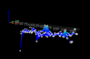
On the off chance I got a partial height map to read, here's what it looked like:

Let me know if you need any further details to help narrow down what's going on. I'm just at a loss as to what the next step might be.
Thank you for everything!
-
@flyscha can you let the machine sit for a while and then grab an M122 B120 output? Does it show a high number of i2c errors?