3 Z motor bedl leveling debug
-
i ended up going 3 motor for bed leveling (instead of 4) motors move bed pivots however calibration not not perfect, one corner is perfect height and 3 other corners off by 2mm or so ... too much so i guess i mess up some where
here are few questions:
-
lead screw position? - is that restive to machine zero? ex my setup is 2 leads screws on left and one on right and the all outdise bed so that makes X-15 Y205 would that concept correct? gping negative outdide bed. also do i mesure actual lead screw location or bracket that hold/touches bed?
-
does order of lead screw matter? or location?
-
for bed config file for some reason when i place probe to 0,205 or any x0 location my head colides with machine body even though normal jog perfectly well goes to 0 on x is that normal?
-
-
@alexus i have 3 point leveling 2 at the front 1 at the back , so my pivot points look like this
Ball joint 3pl
M671 X-15:318:152 Y-15:-15:318 S35 -
- yes, outside the bed positions are normal. usually the position is the pivot point for the bed/gantry. So for a gantry its usually the leadscrews, for a bed its usually the point its mounted.
- the order in M671 matters as it has to match the order the motors are declared in M584.
- if you tell it to probe at X0,Y205 then it will move the probe to be at that point and if the probe is 25mm to the right of the nozzle, the nozzle will end up at X-25.
Owns various duet boards and is the main wiki maintainer for the Teamgloomy LPC/STM32 port of RRF. Assume I'm running whatever the latest beta/stable build is
-
@jay_s_uk
sorry for late reply some how did not get notifications :((((
so machine XY is head noze;eXY, and for bed levelining it is probe XY so i need manually factor in probe offest? well i remember i declared probe offset somewheremotor declaration order is good hint, i will check arangment and try again :))
tnx for helping
-
@jay_s_uk
took me a bit time as i though my table is bent,,, finally setup confirgs with offsets for lead screws outside and zproble compensated relative to nozzle BUT it did not work.... i almost went crazy and then noticed when Z height is being probed and carridge moves say XY only my Z motros are moving... so i realized that while probing next to lead screws proghram was doing heatmap compensation and my reuslts been off all the time caz i mesured old twisted bedmy guess Z aligment needs to be done with all heat map disabled and then heat map can be measured and loaded. so i deiifetly have error in configs.
for now i just renamed heatmap file so it is not loeaded but im getting missing file errors...
whats the proper way to load motor z motors leveling and then load (or not load) build plate heatmaps?
here are my configs
Partial config.g
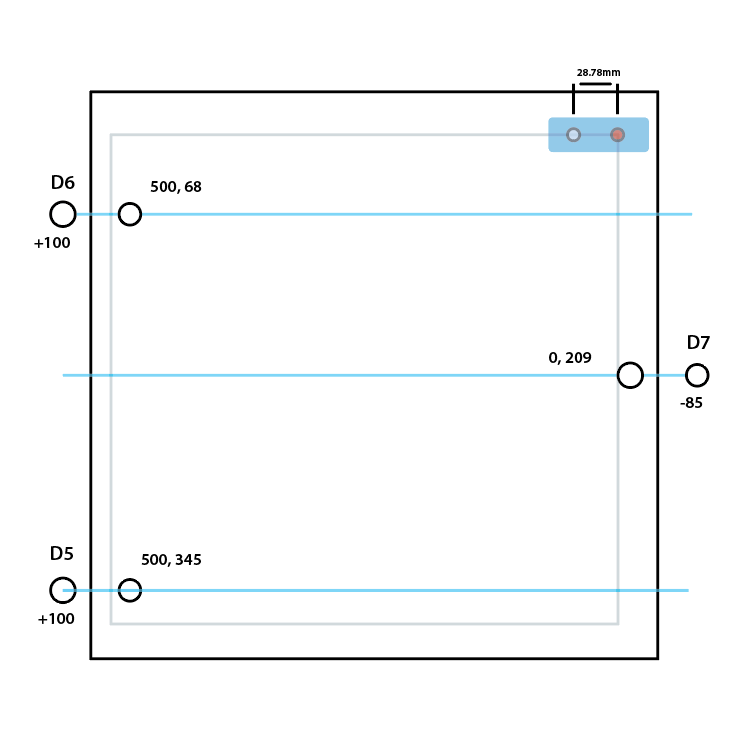
;Lead Screw Locations (Alexus, 3Z Motor Setup)
M671 X600:600:-85 Y345:68:209 S7 ; position of leadscrew/bed pivot point at 5,6,7 Motors (in that oreder), Includes adlustments as screws are outside the bed. S- how much adjusmpents permited mechanically

; Z-Probe
;Alexus BL Touch Declarations
M558 P9 C"^zprobe.in" H5 F100 T2000			; Type 9 BL Touc, w/ pull up, H5 is dive heght 5mm
M950 S0 C"duex.pwm1"						; Duex5 PWM port  - pin 8 yellow wire for servo deploy PWM
G31 X28.78 Y0 Z3.02 P25						; Probe Offest
; END declarations

M557 X50:500 Y0:500 S75	               	; define mesh grid
homez.g
G91              ; relative positioning
G1 H2 Z2 F6000   ; lift Z relative to current position
G90              ; absolute positioning
G1 X250 Y250 F6000 ; go to first probe point
G30              ; home Z by probing the bed

G29 S1			;alexus load heught map
homeall.g
G91                     ; relative positioning
G1 H2 Z2 F6000          ; lift Z relative to current position
G1 H1 X-505 Y-505 F5000 ; move quickly to X and Y axis endstops and stop there (first pass)
G1 H2 X5 Y5 F6000       ; go back a few mm
G1 H1 X-505 Y-505 F360  ; move slowly to X and Y axis endstops once more (second pass)
G90                     ; absolute positioning
G1 X250 Y250 F6000        ; go to first bed probe point and home Z
G30                     ; home Z by probing the bed

G29 S1			;alexus load heught map
bed.g
M561 ; clear any bed transform
;G29  ; probe the bed and enable compensation -- bed heatmap?? quoted out for 4Z testing 10.12.23

G28 ; home


G30 P2 X540 Y345 Z-99999 ;  	D5 probe near a leadscrew
G30 P1 X540 Y68 Z-99999 ; 		D6 probe near a leadscrew
G30 P0 X25 Y209 Z-99999 S3 ; 	D7 probe near a leadscrew - and calibrate 3 motors  //Note X should be 0, but at X0, carridge colides with  gantry edge so i set dfference between probe and extruder
my motor/leadscrew layout looks like this
any comments?
")
-
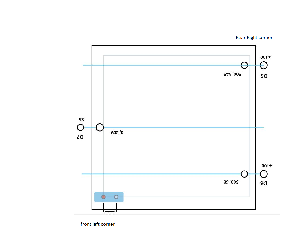
@alexus is your bed in your printer like this?
-
@moth4017
bed on illustration with original orientation is how printer looks when i'm standing in front of it. section where cartridge is depicted is origin X,Y = 0,0. So when i stand in front of printer 0,0 is rear right -
@alexus any reason why you didn't stick to a conventional x0 y0 at front left?
<
-
When doing bed leveling
- cancel any baby-stepping with M290 R0 S0
- cancel mesh compensation with G29 S2
- move the probe to the center of the bed using a G90 G1 command
- set the Z=0 Datum with a G30 command
- use the G32 command to do bed leveling
- once the bed is level do a G30 command again
You can use the "meta" features to do bed leveling in a loop and have it stop when a specified degree of levelness is obtained.
This is from my bed.g file so the numbers won't apply to you. Notice the M671. Some folks put that in config.g. I put everything related to bed leveling in bed.g
M671 X-180:0:180 Y-65:130:-65 S3 ; positions of ball studs

; --- level bed ---

while true
  ; run leveling pass

  ; determine where to probe

  ; --- probe near ball studs ---

  G30 P0 X-145 Y-65 Z-99999    ; probe near ball stud #1
  G30 P1 X0    Y100 Z-99999    ; probe near ball stud #2
  G30 P2 X145  Y-65 Z-99999 S3 ; probe near ball stud #3

  ; check results - exit loop if results are good

  if move.calibration.initial.deviation < 0.02
    break

  ; check pass limit - exit loop if pass limit reached

  if iterations = 5
    break
Also remember that you need to set the Z=0 Datum at bed center:
- when creating the height map
- when loading the height map
Frederick
-
-
While some folks like to have X=0 Y=0 at the corner of their bed I much prefer it to be the center of the bed.
To do this you set your X and Y min/max settings to be +/- half of the total range of each axis.
So for a X axis with 300mm of range of movement and a Y axis of 200mm range the M208 would be:
M208 X-150:150 Y-100:100Now this is just my preference but it is based on lots of experience with 8 different printers - some of which I designed and constructed myself - and all of them have been modified to suit me.
So with X=0 Y=0 at the center of the bed that is where I set the Z=0 Datum by moving the probe to the center and doing the G30.
Some folks like to set the Z=0 Datum using one of the points of the grid they use to create their height map. However I have different heightmaps for different situations and the only thing they have in common is that the center of the bed never changes and is always the center of the height map grid even if it doesn't coincide with a point on the grid.
Frederick
-
@fcwilt
if bed center 0,0 i asusme slicer software needs to know about it?
i run laser cutting machine so flat XY (also do custom buldids) for my brain easier to visualize one corner as absolute zero. though center of bed kinda make sense as id imagine it wold be best tuned point -
@alexus said in 3 Z motor bedl leveling debug:
if bed center 0,0 i asusme slicer software needs to know about it?
Yes, there's usually a printer configuration page for that.
In Cura it's in Settings > Printer > Manage Printers > [select printer] > Machine Settings > Printer > Origin at center
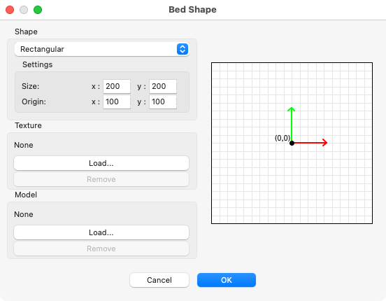
In PrusaSlicer it's in Printer Settings > Bed shape, then set the bed width and the origin on the bed:
There's also a page in the Duet wiki about setting the bed origin in the middle: https://docs.duet3d.com/User_manual/Tuning/Bed_origin
Ian
Bed-slinger - Mini5+ WiFi/1LC | RRP Fisher v1 - D2 WiFi | Polargraph - D2 WiFi | TronXY X5S - 6HC/Roto | CNC router - 6HC | Tractus3D T1250 - D2 Eth
-
@droftarts said in 3 Z motor bedl leveling debug:
setting the bed origin in the middle
All the best folks put the origin there - it's a fung shui thing.

Frederick
-
@ droftarts
tnx i will take a look, i have cura 4.9 (as it seams last to work on Win7)@fcwilt im not too superstitious
just yet maybe after few more failed 24h bulds -
is there way to automate G30 S-1 probe offset detection?
if i change nozzle or adjust screws seams to be too labor intense process to repeat all the time...
to make macro and run loop seams easy, but is there way to get a varianle with values and also how to write it back to config? is that possible? caz i thin just running macro makes more sense -
@alexus said in 3 Z motor bedl leveling debug:
is there way to automate G30 S-1 probe offset detection?
A number of people have created Z probe offset macros. See https://forum.duet3d.com/search?term=macro+Z+offset&in=titles&matchWords=all
But it's going to depend on your printer and probe. If you don't have any way of measuring where the nozzle is (eg like @Exerqtor's macro), you're going to have to manually move the nozzle to the point where it touches the bed first, then you could run a macro that sets Z0, moves up then does G30 S-1, and then stores the probe offset.
Ian
Bed-slinger - Mini5+ WiFi/1LC | RRP Fisher v1 - D2 WiFi | Polargraph - D2 WiFi | TronXY X5S - 6HC/Roto | CNC router - 6HC | Tractus3D T1250 - D2 Eth
-
@droftarts
https://forum.duet3d.com/topic/30411/thoughts-on-an-auto-z-offsett-macro?_=1700771813497that one seams to have good starting point but yea looks like very script will be build specific
good thing im good with coding bad thing im rearly have enough time when no one disrupts me