Issues with pressure advance since RRF 3.4
-
@oliof What extruder jerk are you currently running? After reading your other thread I tried increasing mine to the 3000 range (previously it was 300), but with that setting I started getting various odd noises at sharp corners and seemed to be losing extrusion.
-
@gloomyandy jerk in the 300 to 600 range, acceleration in the 3600 to 6000 range
-
@oliof Thanks, what sort of jerk and acceleration are you running on X, Y, Z? I must say I do find the entire jerk/acceleration thing very confusing having spent some time yesterday searching the forums it seems that values anywhere from high jerk/lowish acceleration to low jerk/high acceleration seem to be in use! There also seems to be some (unresolved) confusion as to when jerk is actually applied with some comments indicating it is only used between moves while others say it is applied (in mode 1) as an initial speed for moves that start at zero.
-
@gloomyandy jerk is a bit of black magic, I spent a weekend with a friend trying to read and understand how its applied in RRF, but I forgot all about it since then.
my jerk/accel on the IDEX are
M566 X360.00 Y210.00 Z18 E300.00 P1                  ; Set maximum instantaneous speed changes (mm/min)
M201 X7500.00 Y4000.00 U7500.00 Z100.00 E6000.00     ; Set accelerations (mm/s^2)
(this is an i3 style portal printer with a prusa bear like frame with a 220^3 print volume)
On the V-Minion my values are
M566 X900.00 Y900.00 Z60.00 E300.00                    ; set maximum instantaneous speed changes (mm/min)
M201 X3000.00 Y3000.00 Z200.00 E6000.00                ; set accelerations (mm/s^2)
(this is an Ormerod style cartesian cantilever printer with a 180^3 print volume)
Just a note that the accelerations on the V-Minion are quite low compared to the klipper config for it, it is on record with 6 minute speed benchies, but I haven't pushed that far yet.
-
@oliof Thanks! It's interesting that your two printers have such a big difference between them! I'm currently using something similar to your first example on my toolchanger with a jerk of 300 and acceleration of 15000, I do get a lot of ringing though so I'll probably be reducing the acceleration somewhat.
Don't want to disrupt this thread, but I wish there was a good way to determine good values for jerk and acceleration with RRF.
-
@gloomyandy the first printer isna glorified ender3 with a terrible y motion system that's dragging it down (also 6mm belts). The second is a very compact machine with 9mm belts designed for rigidity and speed.
To be fair, I haven't even started really tuning the V Minion for fast printing simply for lack of time, or the differences would be even more striking.
-
@oliof Can't resist taking this thread slightly more off topic! How did you select the Jerk speed for the V-Minion? Did you use any test prints to help? I seem to remember it has a big impact on how curves get printed...
-
@oliof
I currently am running a jerk of 1000mm/min with accelerations of 4000 mm/s/s Using a Hemera XS with a volcano style hotend.I used to run by the theory of low jerk high acceleration (J of 500mm/min and 7000mm/s/s) but im now just trying everything in order to isolate the issue
Edit: I should say I am only experiencing this issue on larger nozzles. On a 0.4mm nozzle the issue is imperceptible enough to not be an issue, but on a 0.6mm nozzle the issue is exceptionally bad.
-
I think everyone should learn to use one of these
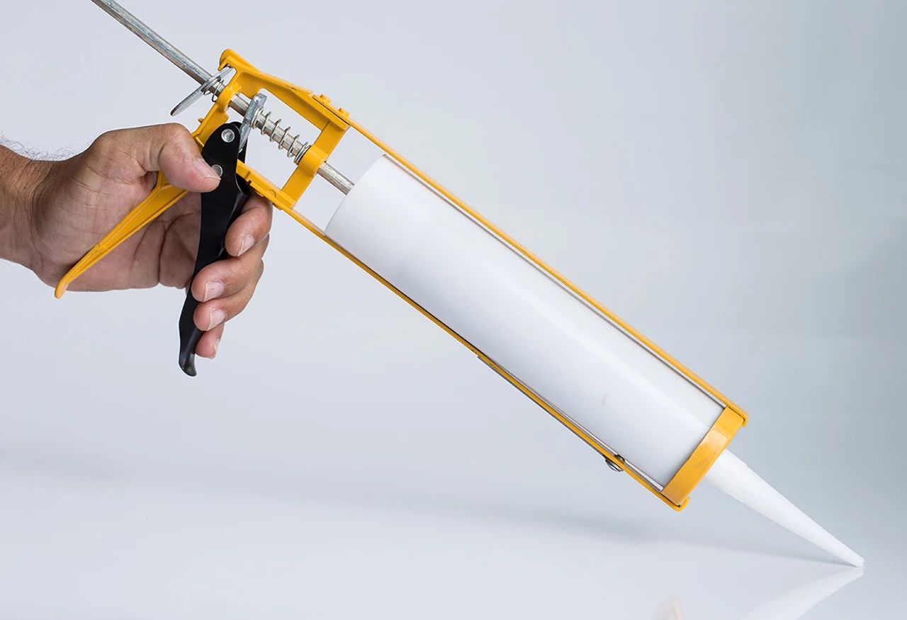
You apply pressure at one end which forces a viscous fluid out of a restricted orifice. Just like a 3D printer extruder. You'll learn a lot about how the flow of a viscous fluid out of a small orifice reacts (or rather hardly reacts) to changes in pressure on the input and how difficult it is to get that flow rate to match the rate to change of movement of the nozzle through space.
Personally, I get best results by keeping the filament flow rate as near constant as possible which essentially means low(ish) acceleration and high(ish) jerk and using pretty much the same speed for all move types.
-
@gloomyandy re:jerk -- I increased it until I got skipping on the motion system, then backed off by 20%. It seems to be a good approach that gets me into a "usable, not too low" range.
@deckingman I had issues with too low acceleration causing print head inertia to be a factor on corner performance. So I tend to aim for low-ish jerk and higher acceleration.
-
@Notepad Are the jerk and acceleration figures you are quoting for the extruder, the movement axis or both?
@deckingman A similar question really what are the actual jerk/acceleration figures you have settled on both for the various axis and the extruder?
-
@gloomyandy I'll get back to you with my actual settings next time I'm at my computer. But given that any print move at any point in time runs at the slowest of XY or E (because they have the synchronised) then extruder jerk will only apply if it's so low that it will slow down X and/or Y. If extruder jerk is not applied to the start of a move, then it won't apply to retractions either, so I can't off hand think of any situation where extruder jerk does apply unless it's so low that it effectively overrides the X or Y axis jerk. For that reason, I set it silly high so that it won't override my X and Y jerk.
-
@gloomyandy With regard to jerk (instantaneous speed change), I look at it like this. If we didn't have it (or it was set to zero) then every move would start at zero speed, accelerate up to the print speed (if the move was long enough) then decelerate to zero speed before commencing the next move. Clearly this would be problematic with short segmented moves such as curves. Therefore it kind of follows that in order to print curves at the same speed as straight lines, the instantaneous speed change should be set to the same as the print speed. So in theory, if we want to print at (say) 60mm/sec, then jerk should be set to 3600 (mm/minute). But in practice, that seems to be too high and also (visually) speed around circular perimeters seems to be the same as the speed on long straight moves with much lower jerk settings. So something is amiss with my logic or the application of jerk. Are we sure that the units for M566 are mm/minute as per the documentation and not mm/sec?
-
@deckingman I think there is an error in your logic here. In the case of a curve the two movement vectors are relatively close to each other (they typically will have a shallow angle between them), so the actual delta change in speed of the X and Y component (lets keep things simple and assume easy kinematics), will be much less than jumping to full speed. Your example is true in the case of a 90 degree corner.
-
@gloomyandy I'm sure you are right in that the angle between line segments plays a part. The description of M566 states (quote) ....
"The model files and GCode files used by repraps generally render circles and other curves shapes as a sequence of straight line segments. If the motors were not allowed any instantaneous speed change, they would have to come to a stop at the junction between each pair of line segments. By allowing a certain amount of instantaneous speed change, printing speed can be maintained when the angle between the two line segments is small enough."
So if we knew how the algorithm worked, then maybe we can determine that the optimum jerk value would be the lowest value which maintains the print speed around a segmented curve? The question is, how many segments or more precisely the angle between them. Thoughts?
-
@gloomyandy So by way of a bit of additional data, I've just run a couple of simple prints. On the basis that I wanted a large angle between segments but not 90 degrees, I made a 200mm diameter, 5 sided hollow "cylinder" with 3mm thick walls. Sliced at 80mm/sec with 3 perimeters (inside and out) that gives 6 perimeter lines using a 0.5m nozzle with no other infill. Then I printed it and played around with M566 on the fly. My default is 1500 for X and Y and that's what I started with. Going higher leads to an audible "clunk" on direction change. This could be more problematic for less robust printer designs. Going lower does have an impact on speed but it's subtle. DWC doesn't update all that fast but I could detect the odd value for top speed which was lower than 80. No such low values could be detected at 1500 Jerk and above.
So maybe that's one strategy for setting jerk. Print a large 5 sided hollow "cylinder" and increase jerk until the machine "clunks", then back off a bit.
As promised, these are the values that work best for me on my machine/
M566 X1500 Y1500 Z300 E3600 M201 X1000 Y1000 Z300 E6000 M203 X21000 Y21000 Z780 E9000 -
@deckingman Interesting! Was the clunk during the printing of the "curve" (rather than at one end)? How much lower did you need to go before you saw a noticeable drop in speed?
From my (rather vague) recollection of school geometry the length of the "sides" does not impact the angle but the number of "sides" does. With 5 sides the angle will be 72degrees with 10 "sides" it would be 36degrees. I'd expect you to be able to use a lower jerk for similar results with a 10 sided object.
If the jerk setting is too low such that the target speed can't be maintained then the length of the sides will start to have an impact as that will (eventually) determine the maximum speed that can be reached between each "corner".
I wonder if a test print which had a large number of "sides" at the base and reduced that number as the height increased would provide a useful insight into how this works on a particular printer?
Maybe we should start a new thread to continue this discussion?
-
@deckingman So if I'm looking at this correctly your settings are counter to the high accel low jerk recommendations for proper
PAinput shaping given elsewhere? I thought, for the CoreXY at least Jerk should have been somewhere around 300 mm/min. -
@gloomyandy said in Issues with pressure advance since RRF 3.4:
@Notepad Are the jerk and acceleration figures you are quoting for the extruder, the movement axis or both?
Those were in relation to extruder jerk and accel settings.
For printing I generally use the following: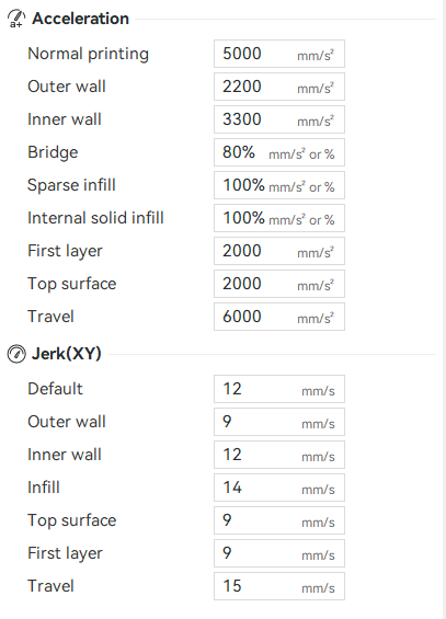
For the actual requested print speeds, the issue is identical if asking for 40mm/s or 300mm/s. As for the printers Jerk and Accel values, these were determined by vibrational analysis and reinforced with real world ABX testing on a unified test print - so I am confident in saying the printer is behaving as intended, isolating the problem to either the extruder, the extrusion control algorithm, or the nozzle flow in general.
I should say, this isnt isolated to one machine, I currently have 5 similar machines behaving the same, and it only becomes apparent on the 0.6mm nozzles and above.
The real bamboo printer manufacturer
-
@edsped Jerk depends on the printers rigidity, If your printer can do X jerk without it inducing vibrations or warp, then you need to go up to that value but no further.
I have identified a weird behaviour with RRF and low jerk, but I believe this will be resolved once IS is done on small line segments.