Problems from the second layer to the 7th layer
-
I use Baby step to get the first layer right, which looks really good.
How much do you need to babystep to get the first layer looking good?
Can you post the first 100-200 lines of a Gcode file that causes this problem? Or upload a whole Gcode file somewhere so we can take a look? It's possible the slicer is inserting speed/acceleration/jerk settings that are overriding those set in config.g.
Some errors in your config.g:
; Aguarde um momento para que as placas de expansão CAN iniciem
o G4 S2
Remove the
ofrom the beginning of the line.M566 X500,00 Y500,00 Z300,00 E1200,00 ; definir alterações instantâneas máximas de velocidade (mm/min)Do not use commas for decimal point. Use decimal point:
.;M208 X0 Y0 Z0 S1 ; definir mínimos do eixoYou have commented out the M208 minimum, but X0 Y0 Z0 is the default.
Check your config.g is valid by sending
M98 P"config.g", and check the response in the console. If there are any errors, please post the response in your reply.Ian
Bed-slinger - Mini5+ WiFi/1LC | RRP Fisher v1 - D2 WiFi | Polargraph - D2 WiFi | TronXY X5S - 6HC/Roto | CNC router - 6HC | Tractus3D T1250 - D2 Eth
-
@droftarts said in Problems from the second layer to the 7th layer:
M98 P"config.g"
Hello, Ian
I did the request and here is the answerM98 P"config.g"HTTP is enabled on port 80
FTP is enabled on port 21
TELNET is disabled
Height map saved to file 0:/sys/heightmap.csv
Error: Failed to load height map from file 0:/sys/heightmap.csv: invalid grid -
400 lines Gcode with problem
G-Code generated by Simplify3D(R) Version 5.1.2 ; Jun 20, 2024 at 10:52:46 PM ; Settings Summary ; processName,PLA ; autoConfigureMaterial,PLA ; autoConfigureQualidade,High ; targetModels,suporte encoder Honda k20 ; profileName,Projeto Uno ; profileVersion,2024-05-08 17:07:31 ; app,S3D-Software 5.1.2 ; technology,fff ; baseProfile,Default ; extruder,Extruder 1 ; toolheadNumber,0 ; nozzleDiameter,0.80000 ; extrusionMultiplier,0.55000 ; extrusionWidthMode,manual ; extrusionWidth,0.62000 ; useRetraction,1 ; retractDistance,6.50000 ; extraRestartDistance,0.20000 ; retractVerticalLift,0.00000 ; retractSpeed,600.00000 ; useCoasting,1 ; coastingDistance,2.10000 ; useWiping,1 ; wipingDistance,6.00000 ; speedMaxFlowRate,900.00000 ; toolheadOffsetX,0.00000 ; toolheadOffsetY,0.00000 ; filamentDiameter,1.75000 ; filamentPricePerKilogram,46.00000 ; filamentDensity,1.25000 ; primaryExtruder,Extruder 1 ; layerHeight,0.20000 ; topSolidLayers,7 ; bottomSolidLayers,1 ; outlinePerimeters,5 ; useVaseMode,0 ; useAdaptiveLayerHeights,0 ; minAdaptiveLayerHeight,0.10000 ; maxAdaptiveLayerHeight,0.40000 ; adaptiveSmoothingLevel,5 ; horizontalOuterCompensation,0.00000 ; horizontalInnerCompensation,0.00000 ; firstLayerUnits,percentage ; firstLayerHeightPercentage,117 ; firstLayerWidthPercentage,100 ; firstLayerSpeedPercentage,80 ; firstLayerHeightAbsolute,0.30000 ; firstLayerWidthAbsolute,0.40000 ; firstLayerSpeedAbsolute,900.00000 ; startPointStrategy,closest ; alignStartPointsX,0.00000 ; alignStartPointsY,0.00000 ; restrictStartPoints,0 ; perimeterPrintingOrder,inside_out ; islandPrintingOrder,closest ; printInfillBeforePerimeters,0 ; useSkirt,1 ; skirtExtruder,Extruder 1 ; skirtLayers,1 ; skirtOffset,0.00000 ; skirtOutlines,15 ; useRaft,0 ; raftExtruder,Extruder 1 ; raftBaseLayers,2 ; raftTopLayers,3 ; raftOffset,3.00000 ; raftSeparationDistance,0.14000 ; raftSpeedUnits,percentage ; raftSpeedPercentage,30 ; raftSpeedAbsolute,600.00000 ; usePrimePillar,0 ; primePillarExtruder,All Extruders ; primePillarWidth,12.00000 ; primePillarLocation,north_west ; primePillarSpeedPercentage,100 ; primePillarInfillPercentage,100 ; autoStopPrimePillar,1 ; primePillarLayersAfterAutoStop,0 ; useOozeShield,0 ; oozeShieldExtruder,All Extruders ; oozeShieldOffset,2.00000 ; oozeShieldOutlines,1 ; oozeShieldSidewallShape,waterfall ; oozeShieldSidewallAngle,30 ; oozeShieldSpeedPercentage,100 ; autoStopOozeShield,1 ; oozeShieldLayersAfterAutoStop,0 ; sparseInfillExtruder,Extruder 1 ; sparseInfillPattern,fast_honeycomb ; sparseInfillRotation,0 ; sparseInfillPercentage,30 ; sparseInfillExtrusionWidthPercentage,115 ; sparseInfillCombinedLayers,1 ; denseInfillLayers,0 ; denseInfillPercentage,55 ; infillOutlineOverlapPercentage,15 ; minInfillLength,1.00000 ; externalInfillPattern,rectilinear ; externalInfillRotation,0 ; solidInfillThresholdArea,25.00000 ; solidInfillExtraExpansion,0.00000 ; useMonotonic,1 ; useDiaphragm,0 ; diaphragmSolidLayers,3 ; diaphragmSpacingLayers,20 ; topLayerExtraExpansion,0.00000 ; topLayerExtrusionModifier,100 ; overrideFanSpeedForTopLayer,0 ; topLayerFanSpeedPercentage,100 ; useIroning,0 ; ironingOutlineOffsetPercentage,50 ; ironingExtrusionWidthPercentage,25 ; ironingExtrusionModifier,15 ; ironingSpeedModifier,30 ; sparseSupportExtruder,Extruder 1 ; sparseSupportInfillPattern,aligned ; sparseSupportInfillRotation,0 ; sparseSupportInfillPercentage,25 ; sparseSupportOutlines,0 ; sparseSupportCombinedLayers,1 ; upperDenseSupportLayers,0 ; lowerDenseSupportLayers,1 ; denseSupportExtruder,Extruder 1 ; denseSupportInfillPercentage,50 ; denseSupportExtraExpansion,0.00000 ; baseSupportLayers,0 ; supportInflationDistance,0.00000 ; supportHorizontalPartOffset,0.70000 ; supportUpperSeparationLayers,1 ; supportLowerSeparationLayers,1 ; temperatureController,Extruder 1 ; enableTemperatureController,1 ; temperatureNumber,0 ; temperatureType,extruder ; stabilizeAtStartup,1 ; temperatureSetpoints,1|210,2|195 ; useIdleCooldown,0 ; cooldownTemperature,150 ; cooldownRequiredIdleTime,180 ; cooldownReheatTime,60 ; temperatureController,Heated Bed ; enableTemperatureController,1 ; temperatureNumber,0 ; temperatureType,platform ; stabilizeAtStartup,1 ; temperatureSetpoints,1|60 ; useIdleCooldown,0 ; cooldownTemperature,150 ; cooldownRequiredIdleTime,180 ; cooldownReheatTime,60 ; fan,Ventoinha ; fanNumber,0 ; fanType,extruder ; blipFanToFullPower,0 ; fanSetpoints,1|0,2|100 ; increaseFanForQuickLayers,0 ; fanMaxQuickLayerTime,45.00000 ; fanMinQuickLayerTime,15.00000 ; maxQuickLayerFanSpeedPercentage,100 ; defaultPrintSpeed,2400.00000 ; outerPerimeterSpeedPercentage,50 ; innerPerimeterSpeedPercentage,80 ; topLayerSpeedPercentage,50 ; solidInfillSpeedPercentage,80 ; sparseSupportSpeedPercentage,80 ; denseSupportSpeedPercentage,70 ; travelSpeedXY,4800.00000 ; travelSpeedZ,1002.00000 ; reduceSpeedForQuickLayers,1 ; speedMaxQuickLayerTime,15.00000 ; minQuickLayerSpeedPercentage,20 ; reduceSpeedForShortPerimeters,1 ; speedMaxShortPerimeterLength,80.00000 ; minShortPerimeterSpeedPercentage,50 ; reduceSpeedForMaxFlowRate,0 ; accelXY,1000.00000 ; accelZ,150.00000 ; accelE,3000.00000 ; jerkXY,600.00000 ; jerkZ,24.00000 ; jerkE,300.00000 ; exportFileFormat,gcode ; useStickyCommands,1 ; use5D,1 ; relativeExtrusionDistances,0 ; allowExtruderAxisZeroing,1 ; independentExtruderAxes,0 ; includeM10123,0 ; includeThumbnailImages,0 ; thumbnailImageEncoding,standard ; thumbnailImageSizes,300|300 ; x3gMachineProfile,r2 ; overrideStepsPerMillimeter,0 ; stepsPerMillimeterX,88.57319 ; stepsPerMillimeterY,88.57319 ; stepsPerMillimeterZ,400.00000 ; stepsPerMillimeterA,96.27520 ; stepsPerMillimeterB,96.27520 ; xyzFileFormatVersion,1 ; makerBotMachineProfile,replicator_5 ; makerBotModelExtruder,mk13 ; makerBotSupportExtruder,mk14_s ; makerBotModelMaterial,pla ; makerBotSupportMaterial,pva ; globalOffsetX,0.00000 ; globalOffsetY,0.00000 ; globalOffsetZ,0.00000 ; applyToolheadOffsets,0 ; buildVolumeShape,rectangular ; buildVolumeX,700.00000 ; buildVolumeY,400.00000 ; buildVolumeZ,400.00000 ; buildVolumeDiameter,200.00000 ; originOffsetX,0.00000 ; originOffsetY,0.00000 ; originOffsetZ,0.00000 ; homingDirectionX,min ; homingDirectionY,min ; homingDirectionZ,min ; mirrorVisualX,0 ; mirrorVisualY,1 ; mirrorVisualZ,0 ; machineBackgroundModel, ; startingScript,M140 S60; faz aquecimento cama |G28; HOME GERAL|G29 V4 T ; AUTO NIVELAMENTO|G1 Y0 Z25 F8000; VAI PRA PONTO DE PURGA|G1 X0 F8000|G1 E60 F250; PURGA FILAMENTO|G92 E0; RESETA EXTRUSOR|G1 X350 F8000 |G1 Y200 Z0 F8000 ; MOVIMENTO para iniciar a impressao ; preLayerChangeScript, ; postLayerChangeScript, ; preRetractionScript, ; postRetractionScript, ; preToolChangeScript, ; postToolChangeScript, ; processChangeScript, ; endingScript,G1 Z300 F6000|M104 S0 ; turn off extruder|M140 S0 ; turn off bed|M84 ; disable motors ; postProcessingScript, ; useBridging,1 ; bridgingThresholdArea,50.00000 ; bridgingInfillExtraExpansion,0.00000 ; bridgingExtrusionModifier,100 ; bridgingSpeedModifier,100 ; overrideFanSpeedForBridging,0 ; bridgingFanSpeedPercentage,100 ; useFixedBridgingAngle,0 ; fixedBridgingAngle,0 ; applyBridgingToPerimeters,0 ; bridgingPerimeterExtraOverlap,0.00000 ; minBridgingPerimeterLength,10.00000 ; useToolChangeRetraction,1 ; toolChangeRetractDistance,12.00000 ; toolChangeExtraRestartDistance,-0.50000 ; toolChangeRetractSpeed,600.00000 ; toolChangePrimeOnFirstUse,0 ; toolChangeRetractAtEnd,0 ; externalThinWallType,perimeters_only ; internalThinWallType,gap_fill ; thinWallAllowedOverlapPercentage,10 ; singleExtrusionMinLength,1.00000 ; singleExtrusionMinWidthPercentage,50 ; singleExtrusionMaxWidthPercentage,200 ; singleExtrusionEndpointExtensionDistance,0.20000 ; onlyRetractWhenCrossingOutlines,1 ; retractBetweenLayers,1 ; retractOnTopLayers,0 ; useRetractionMinTravel,0 ; retractionMinTravel,3.00000 ; useRetractionMinExtrusion,0 ; retractionMinExtrusion,3.00000 ; onlyVerticalLiftOnTopLayers,0 ; retractWhileWiping,0 ; wipingMode,outer_perimeter ; avoidCrossingOutlines,0 ; maxMovementDetourFactor,3.00000 ; openLoopSlicingBehavior,heal ; openLoopThickenWidth,0.50000 ; slicingRegionRepairMode,positive G90 M82 M106 S0 P0 M140 S60 M190 S60 M104 S210 T0 M109 S210 T0 M140 S60; faz aquecimento cama G28; HOME GERAL G29 V4 T ; AUTO NIVELAMENTO G1 Y0 Z25 F8000; VAI PRA PONTO DE PURGA G1 X0 F8000 G1 E60 F250; PURGA FILAMENTO G92 E0; RESETA EXTRUSOR G1 X350 F8000 G1 Y200 Z0 F8000 ; MOVIMENTO para iniciar a impressao ; process PLA ; layer 1, Z = 0.2340 T0 G92 E0.00000 G1 E-6.50000 F600 ; feature skirt ; tool H0.2340 W0.620 G1 Z0.2340 F1002 G1 X321.538 Y175.143 F4800 G92 E0.00000 G1 E6.70000 F600 G92 E0.00000 G1 X322.328 Y173.810 E0.05142 F1920 G1 X323.416 Y172.206 E0.11569 G1 X324.412 Y170.915 E0.16978 G1 X326.044 Y169.079 E0.25128 G1 X327.847 Y167.376 E0.33355 G1 X329.376 Y166.143 E0.39872 G1 X330.287 Y165.482 E0.43606 G1 X331.517 Y164.671 E0.48493 G1 X332.820 Y163.905 E0.53508 G1 X334.162 Y163.208 E0.58525 G1 X335.539 Y162.582 E0.63541 G1 X336.946 Y162.028 E0.68558 G1 X338.454 Y161.524 E0.73833 G1 X340.754 Y160.929 E0.81714 G1 X342.307 Y160.641 E0.86956 G1 X343.807 Y160.443 E0.91975 G1 X345.403 Y160.317 E0.97285 G1 X347.831 Y160.294 E1.05340 G1 X350.265 Y160.482 E1.13440 G1 X351.841 Y160.715 E1.18723 G1 X353.324 Y161.014 E1.23742 G1 X354.789 Y161.390 E1.28759 G1 X356.232 Y161.842 E1.33775 G1 X357.649 Y162.368 E1.38792 G1 X359.038 Y162.968 E1.43808 G1 X360.393 Y163.639 E1.48825 G1 X361.711 Y164.380 E1.53842 G1 X362.989 Y165.188 E1.58859 G1 X364.254 Y166.085 E1.64004 G1 X365.765 Y167.299 E1.70431 G1 X366.913 Y168.343 E1.75580 G1 X367.978 Y169.419 E1.80603 G1 X369.044 Y170.614 E1.85914 G1 X370.482 Y172.473 E1.93712 G1 X371.367 Y173.795 E1.98990 G1 X372.141 Y175.095 E2.04009 G1 X372.846 Y176.433 E2.09026 G1 X373.480 Y177.806 E2.14042 G1 X374.042 Y179.210 E2.19059 G1 X374.530 Y180.641 E2.24076 G1 X374.942 Y182.096 E2.29092 G1 X375.270 Y183.533 E2.33985 G1 X377.187 Y194.033 E2.69391 G1 X379.210 Y196.056 E2.78884 G1 X379.210 Y208.056 E3.18693 G1 X383.210 Y212.056 E3.37460 G1 X383.210 Y231.944 E4.03435 G1 X373.944 Y241.210 E4.46909 G1 X358.056 Y241.210 E4.99615 G1 X354.056 Y237.210 E5.18381 G1 X350.056 Y237.210 E5.31651 G1 X346.056 Y233.210 E5.50417 G1 X342.056 Y233.210 E5.63687 G1 X328.790 Y219.944 E6.25927 G1 X328.790 Y215.691 E6.40035 G1 X321.837 Y203.926 E6.85372 G1 X321.161 Y202.712 E6.89980 G1 X320.457 Y201.275 E6.95290 G1 X319.568 Y199.086 E7.03129 G1 X319.064 Y197.549 E7.08495 G1 X318.574 Y195.675 E7.14921 G1 X318.273 Y194.152 E7.20071 G1 X318.057 Y192.655 E7.25087 G1 X317.917 Y191.110 E7.30235 G1 X317.857 Y189.081 E7.36969 G1 X317.978 Y186.601 E7.45204 G1 X318.308 Y184.184 E7.53297 G1 X318.630 Y182.638 E7.58536 G1 X319.034 Y181.101 E7.63808 G1 X319.822 Y178.775 E7.71956 G1 X320.804 Y176.541 E7.80051 G1 X321.538 Y175.143 E7.85290 G92 E0.00000 G1 E-6.50000 F600 G1 X322.079 Y175.445 F4800 G92 E0.00000 G1 E6.70000 F600 G92 E0.00000 -
@carlinicompetizione said in Problems from the second layer to the 7th layer:
Height map saved to file 0:/sys/heightmap.csv
Error: Failed to load height map from file 0:/sys/heightmap.csv: invalid gridThese errors would be reported by running G29 S3 then G29 S1. I can't see any G29 commands in the config.g you posted earlier, unless you have changed it. You have M501, which runs config_override.g. Can you post that?
In the Gcode output, you are using absolute mode for extrusion; we recommend relative mode (M83)
M82
Also, this line is wrong for RepRapFirmware. This is a Marlin command.
G29 V4 T ; AUTO NIVELAMENTO
I can't see anything else obviously wrong with the Gcode file. It should not changing the motor settings in config.g. It does have some Z movements at maximum speed, so you should try moving the bed at these speeds; try sending the following:
G1 Z25 F8000
G1 Z5 F8000
G1 Z25 F8000
G1 Z5 F8000
Can you post the whole Gcode file? Add ".txt" to the end of the file name, and you should be able to upload it to the forum.
Ian
Bed-slinger - Mini5+ WiFi/1LC | RRP Fisher v1 - D2 WiFi | Polargraph - D2 WiFi | TronXY X5S - 6HC/Roto | CNC router - 6HC | Tractus3D T1250 - D2 Eth
-
Ian, thank you very much for the guidance, I did as you suggested,
The M208 is actually deactivated, I activated it. The Z tests with perfect F8000 drops 25 5 without any problems! When I send the command G29 S3 and G29 S1 there is an error reading the map and I cannot load it. I'm going to change the CURA configuration to RRPP even today it is with Marlin, but in config.g the command is as M83. -
It may be that the Map is not loading, I need to add some command to the config. g to load and activate the created map?
-
@carlinicompetizione
Check the grid spacing in M557 that doesn't make sense to me.
You have only defined 4 points in the grid. -
@carlinicompetizione said in Problems from the second layer to the 7th layer:
I need to add some command to the config. g to load and activate the created map?
There are several ways to do this.
I have added it to my homing routine.
But it also works at the end of the config.g. However, you must definitely call G29 before printing.
There are also several options for G29. I only load the saved map.
If the printer is stable, the mesh does not need to be recreated each time. -
@carlinicompetizione No, you certainly shouldn't save the map in config.g, as no map is in use; I'm not exactly sure what this does, but most likely creates a blank map, hence the 'invalid grid' error.
Also, you shouldn't load a map during config.g, because you have not homed the Z axis to set the Z datum point.I've just remembered you mentioned putting M374 and M375 in config.g, please remove these. They are synonymous with G29 S3 then G29 S1. M376 is okay.
You should home Z, then load the map or run the mesh bed scan, then home Z again. That will give the most reliable results from a saved mesh. You can do this in homez.g, homeall.g, in the start.g of the slicer, or create the file sys/mesh.g, which is run when G29 is sent. See https://docs.duet3d.com/en/User_manual/Reference/Gcodes#g29-mesh-bed-probe and https://docs.duet3d.com/en/User_manual/Connecting_hardware/Z_probe_mesh_bed
But I don't think this is related to the problem of your machine not moving for the second layer, though you could try a test without mesh bed levelling enabled.
Ian
Bed-slinger - Mini5+ WiFi/1LC | RRP Fisher v1 - D2 WiFi | Polargraph - D2 WiFi | TronXY X5S - 6HC/Roto | CNC router - 6HC | Tractus3D T1250 - D2 Eth
-
Having activated the M208 seems to have solved the problem, but it is still not going down, do the first one each, and remain in the same Z, it only starts to change from the 4th layer that starts to go down the Z, the second and the third it prints even Z then there is that excess plastic, the interesting thing is that the display shows the value of X,Y, Z, when the extruder moves in the map, this does not show, it is only from the 4th layer that it starts to descend, for example, it starts printing at Z=2 9 this value is the baby step. finishes the first layer and goes to the second and it doesn't change, it stays at Z=2, finishes the second layer and goes to the third and Z=2 continues. When the 4th layer begins, Z = 2.4 because I established a layer height of 0.4 mm in Simplify 3D. in fact it should be at Z=3.6. the extruder starts hitting the print.
-
@oliof said in Problems from the second layer to the 7th layer:
@carlinicompetizione A raspberry pi does not help here. There is some chance that this is not a software, but a hardware issue, i.e. the mechanism raising the nozzle (or lowering the bed) may be binding until it overcomes the early layers.
You could try commanding the printer without issuing a full print, doing moves with the G0 and G1 commands after homing, to see how things behave.
I would like to know if there is a possible solution to this problem that the system has that disregards the first layers?, the printer is industrial, and I have already spent too much time making it work with this Duet 3D 6HC card. I really need a solution, otherwise I have to change my motherboard to another brand that is less problematic and can print without so much hassle.
-
@carlinicompetizione If we knew the answer to this issue, we would have told you already! We have to find out the information to try and solve it from you, so any information you can give us helps.
it starts printing at Z=2 9 this value is the baby step
I think you're saying that you are using 2mm of baby stepping. I'd guess this is the issue, and it's probably because you have not set the Z probe Z offset correctly. Baby stepping usually only needs to be a small adjustment, maybe +/- half a layer height. Much more than that, yes, odd things are likely to happen.
Please set the Z probe Z offset again. Currently the X and Y offsets are set to 0 as well, so set them to. You're using a BLTouch I think, so there should definitely be an X, Y and Z offset. Your current probe offset is:
G31 P500 Y0; definir valor de disparo da sonda Z, deslocamento e altura de disparo
G31 P500 X0 Z0.85 ; definir valor de disparo da sonda Z, deslocamento e altura de disparo
You can put this on one like together, like this:
G31 P500 X0 Y0 Z0.85 ; definir valor de disparo da sonda Z, deslocamento e altura de disparoFor setting Z probe X, Y and Z offset, see https://docs.duet3d.com/en/User_manual/Connecting_hardware/Z_probe_testing
Ian
Bed-slinger - Mini5+ WiFi/1LC | RRP Fisher v1 - D2 WiFi | Polargraph - D2 WiFi | TronXY X5S - 6HC/Roto | CNC router - 6HC | Tractus3D T1250 - D2 Eth
-
I believe we have discovered the problem. I started to slow down
changing microsteps from 16 to 8 and Z began to move as programmed in the slicer. Without being satisfied with the result, I went back to 16 microsteps and lowered the instantaneous on Z by approximately 30%. Then I managed to print a piece with a higher quality than what I had until then. Even so, the first to second layer is not respecting the programmed distance.
EX: the first layer starts at Z=0.40mm (this height is correct according to the baby step, also from 0.40mm or less. In the slicer, a layer height of 0.3mm was determined, so the second layer would start with Z=0.7mm , but it was only for 0.51mm, so I did a manual intervention just to understand if the next layers would maintain this flaw (I paused the printing and lowered the table manually to complete the 0.19 mm) when the second layer was finished and the third started. the value was already correct Z=0.81 mm. It seems to me like a bug in the firmware, it doesn't make sense to do that. -
@carlinicompetizione Did you try any of the things I suggested?
- calibrate your Z probe offset - https://docs.duet3d.com/en/User_manual/Connecting_hardware/Z_probe_testing
- try a print without baby stepping - set
G92 Z0with the nozzle just touching the bed before printing, don't home Z at the beginning of the print - try a print without mesh bed compensation
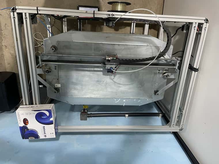
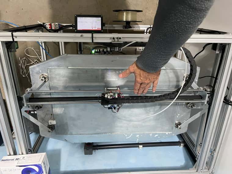
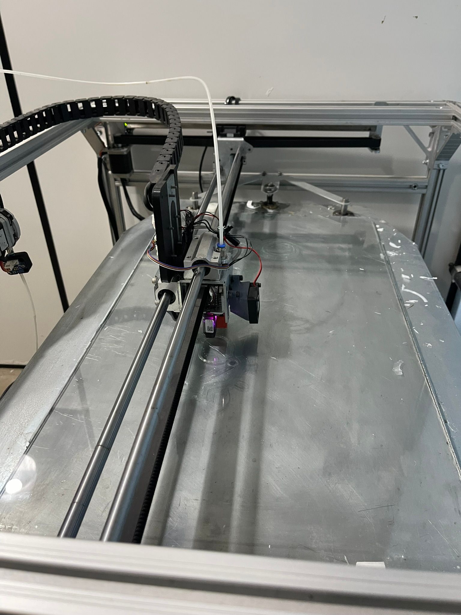
And one more thing to try: yes, your Z jerk looks high to me, and so does your acceleration and maximum speed for Z, especially for the steps per mm on Z. I don't know the layout of your machine, how heavy the bed is, or even if the bed moves in Z, or if your gantry moves in Z. So the values you have might be okay, but might not be. Maybe post a picture of your printer so we can get a better idea of the size. For example, I have a bed slinger with 200x200mm bed and 2mm lead M8 leadscrews, and can only move them this fast before skipping (though they are quite small NEMA 17 motors):
M92 Z800  ; set steps per mm
M566 Z12  ; set maximum instantaneous speed changes (mm/min)
M203 Z600 ; set maximum speeds (mm/min)
M201 Z20  ; set accelerations (mm/s^2)
Yours were set as:
M92 Z1650.50
M566 Z300.00
M203 Z1000.00
M201 Z250.00
Though I'm not sure why your settings would not work to start with, and then work okay at later layers. If you can share a full Gcode file, that may help.
I'd suggest setting low values for jerk, acceleration and maximum speed (ie like mine), and check if movement is correct. If it is, you can then increase them until you find the limit.
Ian
Bed-slinger - Mini5+ WiFi/1LC | RRP Fisher v1 - D2 WiFi | Polargraph - D2 WiFi | TronXY X5S - 6HC/Roto | CNC router - 6HC | Tractus3D T1250 - D2 Eth
-
-
-
I am wondering if commas and decimals are interchangeable in config.g.
Your M566 uses commas and the rest use decimals.
@carlinicompetizione said in Problems from the second layer to the 7th layer:
M566 X500,00 Y500,00 Z300,00 E1200,00 ; definir alterações instantâneas máximas de velocidade (mm/min)
M203 X3000.00 Y3000.00 Z1000.00 E1200.00 ; definir velocidades máximas (mm/min)
M201 X500.00 Y500.00 Z250.00 E1200.00 ; definir acelerações (mm/s^2) -
@tas
In the config.g in the file everything is with a dot, but I'll check, you'll see that something typing is getting in the way too -
@droftarts
In these days I made several impressions to fine-tune the resolution that until then I could not make due to so much instability of operation. The last impressions with a 0.8 beak are getting good. using simplify3D that seems somewhat limited compared to Cura.
Even so, when starting the second layer, the table does not go down to the correct value. When it goes to third, it works normally. It's very strange. It doesn't make any sense. I lowered the Jerk values a lot from 500mm/min to 300mm/min. The z was at 110 I went to 60mm/min, but I will lower it more to see if it solves the problem of the second layer, it is interesting because it goes down only half the value stipulated by the slicer. But only in this layer that does this. Then take off cute. -
Sounds like mechanical binding on the z axis. Are you able to turn the z axis by hand and feel for change in resistance?