Duet3D Logo Duet3D
    • Tags
    • Documentation
    • Order
    • Register
    • Login

    6XD I/O >> Issue solved

    Scheduled Pinned Locked Moved
    Duet Hardware and wiring
    4
    121
    5.2k
    Loading More Posts
    • Oldest to Newest
    • Newest to Oldest
    • Most Votes
    Reply
    • Reply as topic
    Log in to reply
    This topic has been deleted. Only users with topic management privileges can see it.
    • tecnoundefined
      tecno @dc42
      last edited by

      @dc42
      C = pin 2

      PXL_20240917_085540092.jpg PXL_20240917_085626813.jpg

      The optocouplers are on the existing PCB on this PnP machine. All I/O are 24 V

      So I assume I can use io1.out and use io1.in for home etc

      tecnoundefined 1 Reply Last reply Reply Quote 0
      • tecnoundefined
        tecno @tecno
        last edited by

        Anybody care to advise?

        droftartsundefined 1 Reply Last reply Reply Quote 0
        • droftartsundefined
          droftarts administrators @tecno
          last edited by

          @tecno I need a bit of context. What does this PCB actually do? Does it turn something(s) on and off? Please post an image of the other side of the board, too.

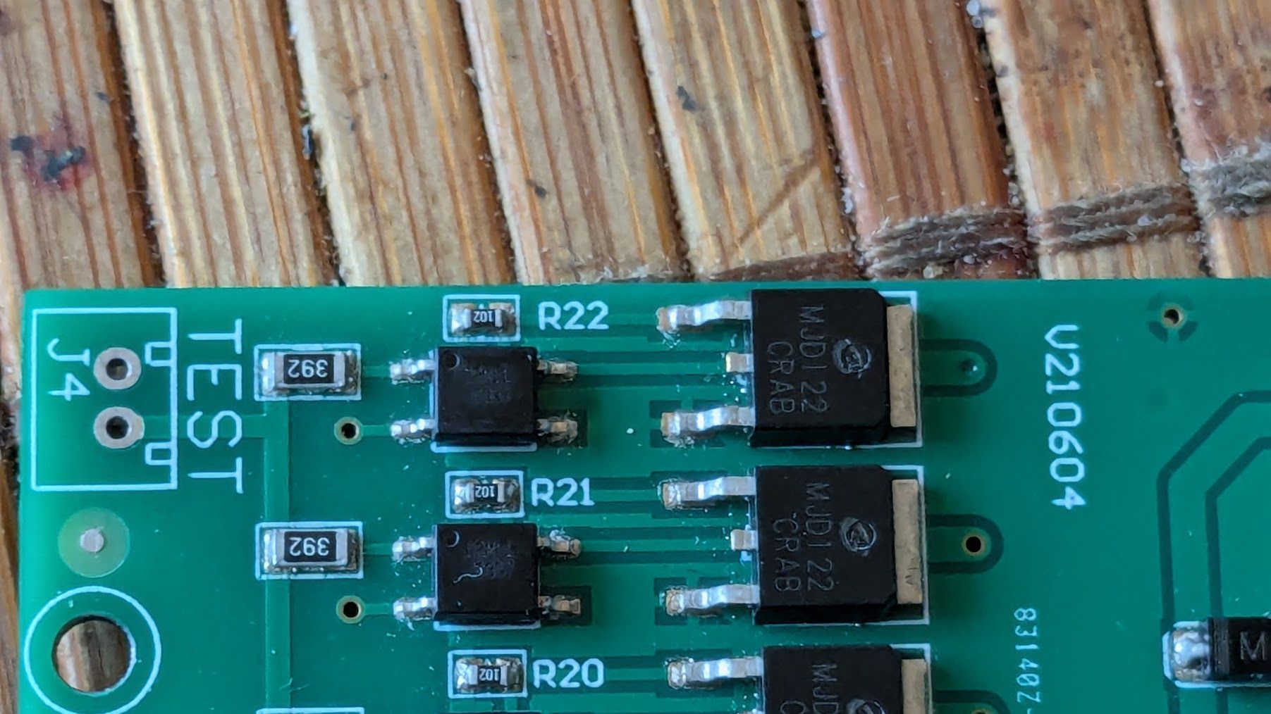
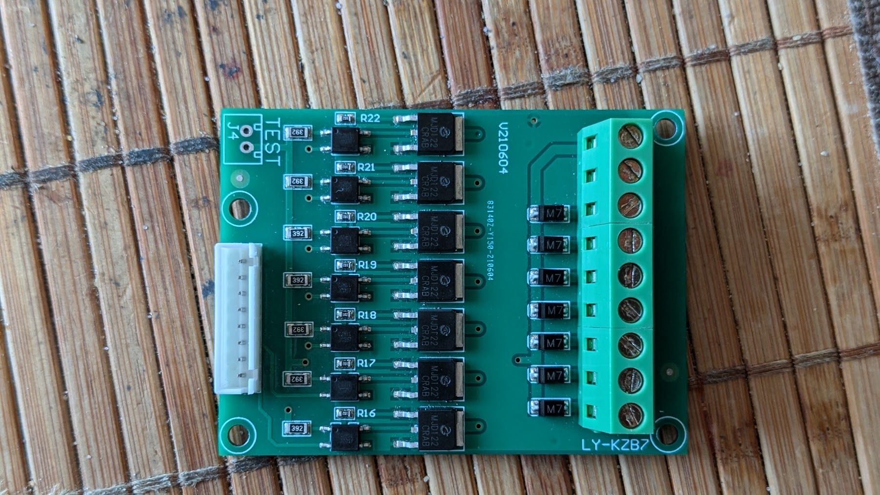
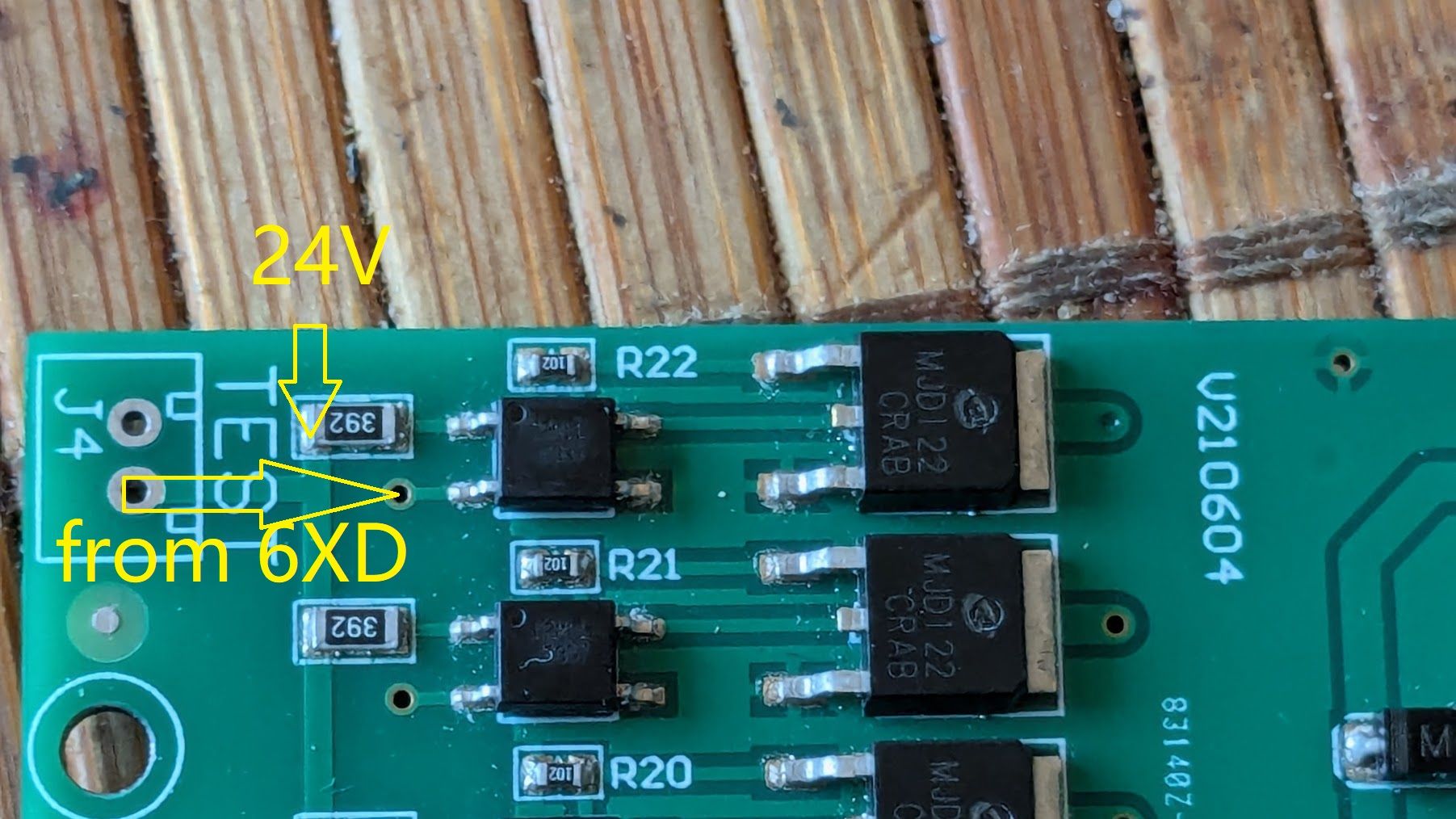
          I'd guess it is an output board, as the optocouplers look like they switch MOSFETs, and control whatever is connected on the green headers on the right. There are 8 pins on the white connector, presumably +V on one pin, and 7 pins to switch each of the 7 optocouplers to GND. There are 9 output terminals; presumably +V and GND, plus the 7 outputs from the MOSFETs?

          Ian

          Bed-slinger - Mini5+ WiFi/1LC | RRP Fisher v1 - D2 WiFi | Polargraph - D2 WiFi | TronXY X5S - 6HC/Roto | CNC router - 6HC | Tractus3D T1250 - D2 Eth

          tecnoundefined 1 Reply Last reply Reply Quote 0
          • tecnoundefined
            tecno @droftarts
            last edited by

            @droftarts
            Hi Ian,
            You have observed the board correctly. This bord gets outputsignals from controller via the ribboncable.
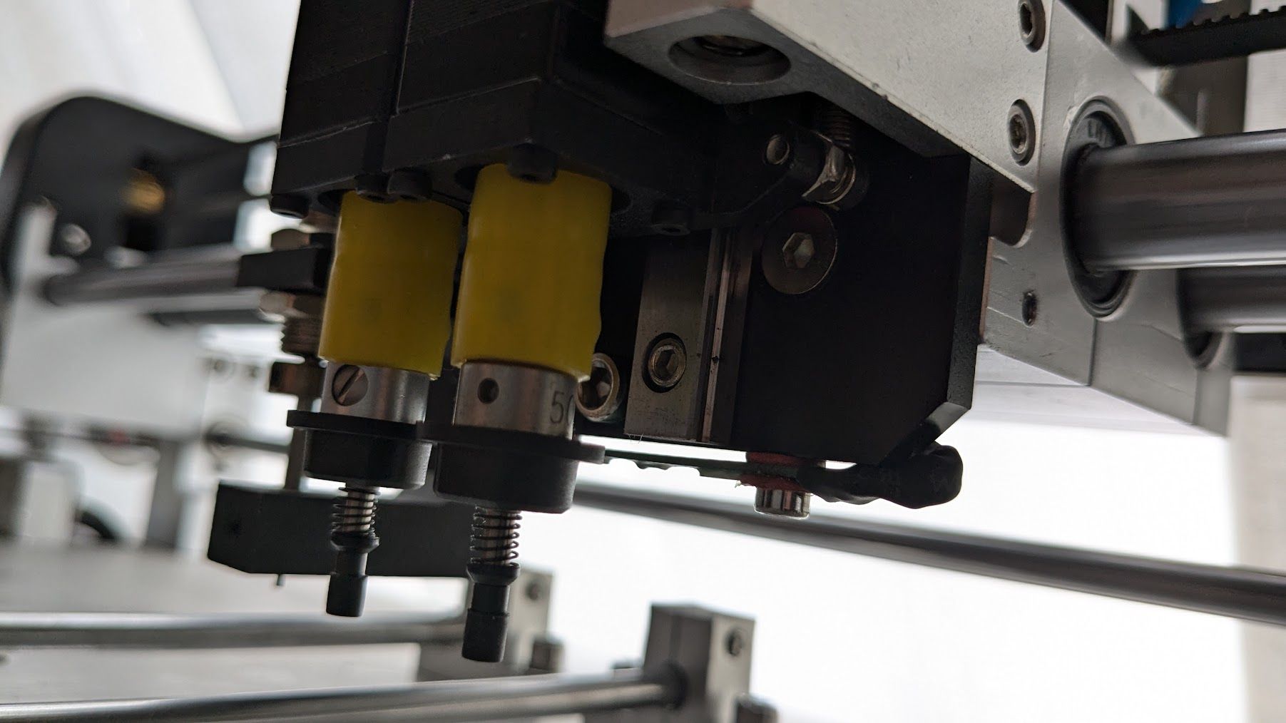
            Controlls nozzle vacuum, pin feeder solenoid Air controll, Xross cursor, LED light and vacuum power.

            Cheers
            Bengt

            tecnoundefined droftartsundefined 2 Replies Last reply Reply Quote 0
            • tecnoundefined
              tecno @tecno
              last edited by

              PXL_20240917_085540092.jpg

              1 Reply Last reply Reply Quote 0
              • droftartsundefined
                droftarts administrators @tecno
                last edited by

                @tecno If you can look up the product number of the optocouplers (I can't see the part number on them from you pictures), it may be they don't need 24V to turn them on and off. However, if it's wired like this:

                There are 8 pins on the white connector, presumably +V on one pin, and 7 pins to switch each of the 7 optocouplers to GND.

                and

                C = pin 2

                i.e. the R22 optocoupler C pin goes to the second pin down on the connector, the first being +V and shared to the A pin on all Optocouplers (please check if there's continuity between pin 1 and the A pin on each optocoupler with a multimeter), then you need to switch the C pin on each optocoupler to GND, which isn't what the io.out pins do (they output a 3.3V signal). I think you'll need to use the OUT pins for that, which do switch to GND. They should also all be able to cope with 24V.

                Ian

                Bed-slinger - Mini5+ WiFi/1LC | RRP Fisher v1 - D2 WiFi | Polargraph - D2 WiFi | TronXY X5S - 6HC/Roto | CNC router - 6HC | Tractus3D T1250 - D2 Eth

                tecnoundefined 2 Replies Last reply Reply Quote 0
                • tecnoundefined
                  tecno @droftarts
                  last edited by

                  @droftarts

                  C2M11

                  droftartsundefined 1 Reply Last reply Reply Quote 0
                  • tecnoundefined
                    tecno @droftarts
                    last edited by

                    @droftarts said in 6XD I/O:

                    They should also all be able to cope with 24V.

                    That confirms my question, just wanted to be sure and safe 🙂

                    1 Reply Last reply Reply Quote 0
                    • droftartsundefined
                      droftarts administrators @tecno
                      last edited by

                      @tecno said in 6XD I/O:

                      C2M11

                      I can't find any optocoupler with that marking.

                      That confirms my question, just wanted to be sure and safe 🙂

                      That's the OUT pins, though, not the IO.out pins, just to be clear! IO.out pins are only 3.3V tolerant, wiring 24V to them will destroy the MCU.

                      Ian

                      Bed-slinger - Mini5+ WiFi/1LC | RRP Fisher v1 - D2 WiFi | Polargraph - D2 WiFi | TronXY X5S - 6HC/Roto | CNC router - 6HC | Tractus3D T1250 - D2 Eth

                      tecnoundefined 1 Reply Last reply Reply Quote 0
                      • tecnoundefined
                        tecno @droftarts
                        last edited by

                        @droftarts
                        6f05f2d8-26cb-4ade-a342-882d8f31fd3b-image.png

                        These 3 only?

                        droftartsundefined 1 Reply Last reply Reply Quote 0
                        • droftartsundefined
                          droftarts administrators @tecno
                          last edited by

                          @tecno You have the 6x fan outputs as well, 3x 4-pin, 3x 2-pin.

                          Ian

                          Bed-slinger - Mini5+ WiFi/1LC | RRP Fisher v1 - D2 WiFi | Polargraph - D2 WiFi | TronXY X5S - 6HC/Roto | CNC router - 6HC | Tractus3D T1250 - D2 Eth

                          tecnoundefined 1 Reply Last reply Reply Quote 0
                          • tecnoundefined
                            tecno @droftarts
                            last edited by

                            @droftarts

                            Thanks Ian, appreciated.

                            tecnoundefined 1 Reply Last reply Reply Quote 0
                            • tecnoundefined
                              tecno @tecno
                              last edited by

                              @droftarts
                              ccb296f8-231c-44d9-9969-2a3087b585e8-image.png

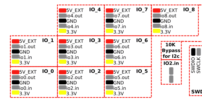
                              io1.in is capable to take 24V ??

                              droftartsundefined 1 Reply Last reply Reply Quote 0
                              • droftartsundefined
                                droftarts administrators @tecno
                                last edited by droftarts

                                @tecno Yes, but io#.in pins don't switch to GND. They are for reading a voltage input, eg endstop, or digital input, eg communications. See https://docs.duet3d.com/Duet3D_hardware/Duet_3_family/Duet_3_Mainboard_6XD_Hardware_Overview#inputoutput-port-capabilities

                                Ian

                                Bed-slinger - Mini5+ WiFi/1LC | RRP Fisher v1 - D2 WiFi | Polargraph - D2 WiFi | TronXY X5S - 6HC/Roto | CNC router - 6HC | Tractus3D T1250 - D2 Eth

                                tecnoundefined 1 Reply Last reply Reply Quote 0
                                • tecnoundefined
                                  tecno @droftarts
                                  last edited by tecno

                                  @droftarts
                                  OK, will have to sort out my input I/O's and see how they work.

                                  tecnoundefined 1 Reply Last reply Reply Quote 0
                                  • tecnoundefined
                                    tecno @tecno
                                    last edited by

                                    @droftarts

                                    All limits are OPTO's X, Y, Z1 and Z2 + one more that I can not figure out is Lz

                                    Also Emergency switch did go to old driver.

                                    droftartsundefined 1 Reply Last reply Reply Quote 0
                                    • droftartsundefined
                                      droftarts administrators @tecno
                                      last edited by

                                      @tecno They can connect to the IO headers. See https://docs.duet3d.com/en/User_manual/Connecting_hardware/Sensors_endstops#h-33v-compatible-optical-endstop
                                      You can use 3.3V or 5V for them. Or do they need 24V too?

                                      Emergency stop can go to any IO input, too. See https://docs.duet3d.com/en/User_manual/Connecting_hardware/IO_E_stop

                                      Ian

                                      Bed-slinger - Mini5+ WiFi/1LC | RRP Fisher v1 - D2 WiFi | Polargraph - D2 WiFi | TronXY X5S - 6HC/Roto | CNC router - 6HC | Tractus3D T1250 - D2 Eth

                                      tecnoundefined 1 Reply Last reply Reply Quote 0
                                      • tecnoundefined
                                        tecno @droftarts
                                        last edited by

                                        @droftarts

                                        24V ;(

                                        droftartsundefined 1 Reply Last reply Reply Quote 0
                                        • droftartsundefined
                                          droftarts administrators @tecno
                                          last edited by

                                          @tecno said in 6XD I/O:

                                          24V ;(

                                          That shouldn't matter, as the 6XD IO#.in are 30V-tolerant. Just supply the optos with 24V, signal wire to the IO#.in.

                                          Ian

                                          Bed-slinger - Mini5+ WiFi/1LC | RRP Fisher v1 - D2 WiFi | Polargraph - D2 WiFi | TronXY X5S - 6HC/Roto | CNC router - 6HC | Tractus3D T1250 - D2 Eth

                                          tecnoundefined 1 Reply Last reply Reply Quote 0
                                          • tecnoundefined
                                            tecno @droftarts
                                            last edited by

                                            @droftarts
                                            OK, thanks

                                            Lz mystery? Looks like a loadcell? Just behind toolheads.

                                            PXL_20240918_131600490.jpg

                                            droftartsundefined 1 Reply Last reply Reply Quote 0
                                            • First post
                                              Last post
                                            Unless otherwise noted, all forum content is licensed under CC-BY-SA