6XD I/O >> Issue solved
-
-
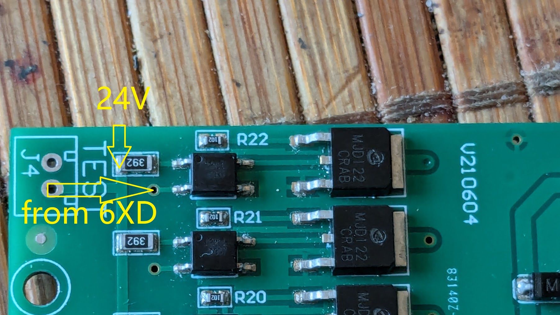
@tecno If you can look up the product number of the optocouplers (I can't see the part number on them from you pictures), it may be they don't need 24V to turn them on and off. However, if it's wired like this:
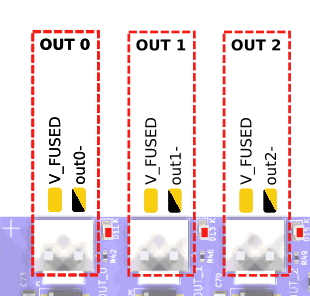
There are 8 pins on the white connector, presumably +V on one pin, and 7 pins to switch each of the 7 optocouplers to GND.
and
C = pin 2
i.e. the R22 optocoupler C pin goes to the second pin down on the connector, the first being +V and shared to the A pin on all Optocouplers (please check if there's continuity between pin 1 and the A pin on each optocoupler with a multimeter), then you need to switch the C pin on each optocoupler to GND, which isn't what the io.out pins do (they output a 3.3V signal). I think you'll need to use the OUT pins for that, which do switch to GND. They should also all be able to cope with 24V.
Ian
-
C2M11
-
@droftarts said in 6XD I/O:
They should also all be able to cope with 24V.
That confirms my question, just wanted to be sure and safe
")
-
-
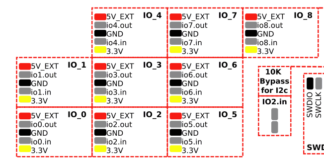
These 3 only?
-
@tecno You have the 6x fan outputs as well, 3x 4-pin, 3x 2-pin.
Ian
-
Thanks Ian, appreciated.
-
io1.in is capable to take 24V ??
-
@tecno Yes, but io#.in pins don't switch to GND. They are for reading a voltage input, eg endstop, or digital input, eg communications. See https://docs.duet3d.com/Duet3D_hardware/Duet_3_family/Duet_3_Mainboard_6XD_Hardware_Overview#inputoutput-port-capabilities
Ian
-
@droftarts
OK, will have to sort out my input I/O's and see how they work. -
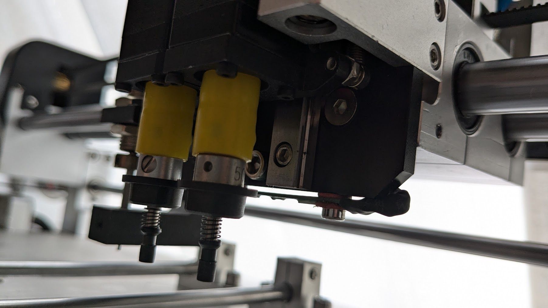
All limits are OPTO's X, Y, Z1 and Z2 + one more that I can not figure out is Lz
Also Emergency switch did go to old driver.
-
@tecno They can connect to the IO headers. See https://docs.duet3d.com/en/User_manual/Connecting_hardware/Sensors_endstops#h-33v-compatible-optical-endstop
You can use 3.3V or 5V for them. Or do they need 24V too?Emergency stop can go to any IO input, too. See https://docs.duet3d.com/en/User_manual/Connecting_hardware/IO_E_stop
Ian
-
24V ;(
-
-
-
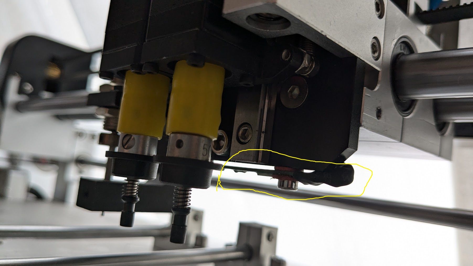
Lz mystery? Looks like a loadcell? Just behind toolheads.
If you mean the thing the pokes out looking like a button, it could be a microswitch or pressure switch, or tool offset switch, or limit switch in case of problems. Otherwise, I don't really know.
Edit: or is that the red LED cross target?
Ian
-
-

-
@tecno Maybe an inductive probe? ie for creating a mesh of the board if it is warped? This video talks about "automatically correct the offset caused by PCB irregularities". https://youtu.be/eW8JtbPlvKQ?t=29
For wiring, see https://docs.duet3d.com/en/User_manual/Connecting_hardware/Z_probe_connecting#npn-output-normally-open-inductive-or-capacitive-sensor
But could be NPN or PNP.Ian