6XD I/O >> Issue solved
-
All limits are OPTO's X, Y, Z1 and Z2 + one more that I can not figure out is Lz
Also Emergency switch did go to old driver.
-
@tecno They can connect to the IO headers. See https://docs.duet3d.com/en/User_manual/Connecting_hardware/Sensors_endstops#h-33v-compatible-optical-endstop
You can use 3.3V or 5V for them. Or do they need 24V too?Emergency stop can go to any IO input, too. See https://docs.duet3d.com/en/User_manual/Connecting_hardware/IO_E_stop
Ian
Bed-slinger - Mini5+ WiFi/1LC | RRP Fisher v1 - D2 WiFi | Polargraph - D2 WiFi | TronXY X5S - 6HC/Roto | CNC router - 6HC | Tractus3D T1250 - D2 Eth
-
24V ;(
-
24V ;(
That shouldn't matter, as the 6XD IO#.in are 30V-tolerant. Just supply the optos with 24V, signal wire to the IO#.in.
Ian
Bed-slinger - Mini5+ WiFi/1LC | RRP Fisher v1 - D2 WiFi | Polargraph - D2 WiFi | TronXY X5S - 6HC/Roto | CNC router - 6HC | Tractus3D T1250 - D2 Eth
-
-
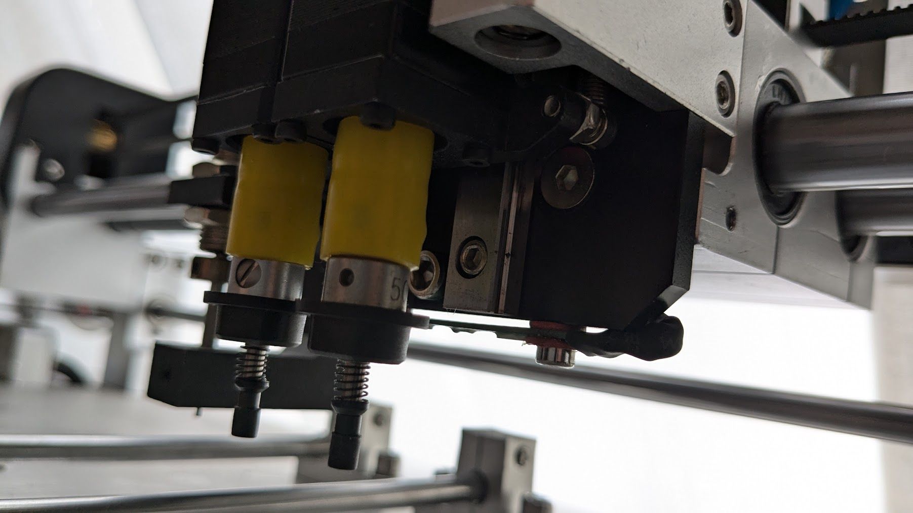
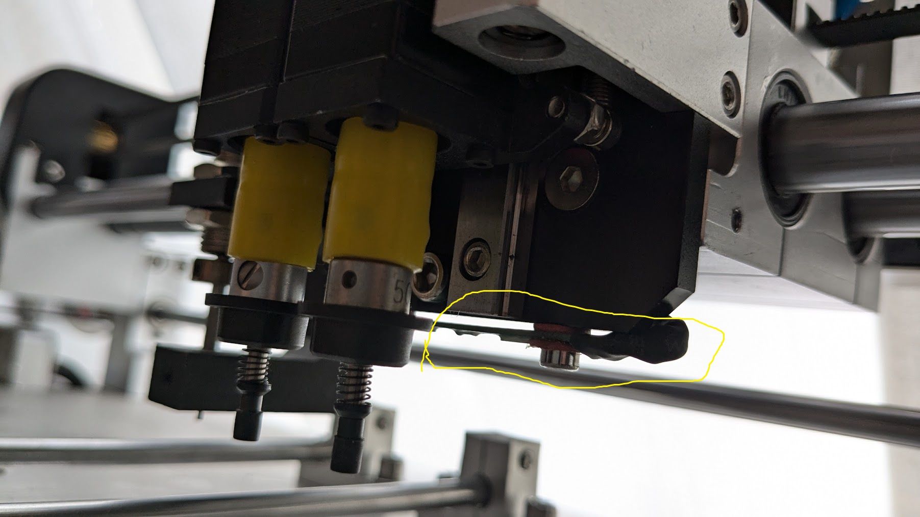
Lz mystery? Looks like a loadcell? Just behind toolheads.
If you mean the thing the pokes out looking like a button, it could be a microswitch or pressure switch, or tool offset switch, or limit switch in case of problems. Otherwise, I don't really know.
Edit: or is that the red LED cross target?
Ian
Bed-slinger - Mini5+ WiFi/1LC | RRP Fisher v1 - D2 WiFi | Polargraph - D2 WiFi | TronXY X5S - 6HC/Roto | CNC router - 6HC | Tractus3D T1250 - D2 Eth
-
-

-
@tecno Maybe an inductive probe? ie for creating a mesh of the board if it is warped? This video talks about "automatically correct the offset caused by PCB irregularities". https://youtu.be/eW8JtbPlvKQ?t=29
For wiring, see https://docs.duet3d.com/en/User_manual/Connecting_hardware/Z_probe_connecting#npn-output-normally-open-inductive-or-capacitive-sensor
But could be NPN or PNP.Ian
Bed-slinger - Mini5+ WiFi/1LC | RRP Fisher v1 - D2 WiFi | Polargraph - D2 WiFi | TronXY X5S - 6HC/Roto | CNC router - 6HC | Tractus3D T1250 - D2 Eth
-
OK, will take on that one later on as I see it is not criticall for now to get this machine up and running.
Thanks once again Ian, I really appreciate your kind help.
So back to the machine and start crimping some connectors.
-
Part in yellow circle = LED light (feeling stupid)
-
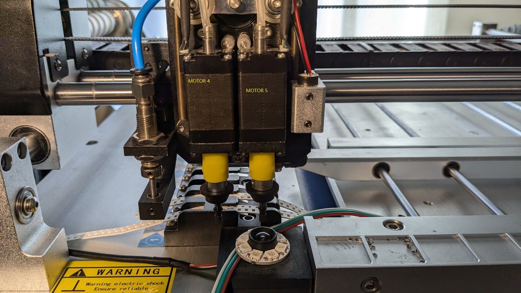
Now that I have all ports set OK I just found out that Driver 5 is not responding. Earlier test there was a mess on driver numbering so I took it for granted that all motors work.
If I switch wires from Driver 4 to 5 and vice versa the fault follows the cable. Bommer ....
-
-
@tecno said in 6XD I/O >> Faulty Driver 5:
If I switch wires from Driver 4 to 5 and vice versa the fault follows the cable. Bommer ....
Do you mean if you switch the wires, the motor then stops working on Driver 4? Sounds like a cable issue.
Ian
Bed-slinger - Mini5+ WiFi/1LC | RRP Fisher v1 - D2 WiFi | Polargraph - D2 WiFi | TronXY X5S - 6HC/Roto | CNC router - 6HC | Tractus3D T1250 - D2 Eth
-
Cable from driver 5 is not working if i use it on motor 4
Cable from driver 4 is working if used on motor 5
So Driver 5 on 6DX is not working.
Cheers
Bengtps. Camera and LED light is coming up next
")
-
@tecno said in 6XD I/O >> Faulty Driver 5:
Cable from driver 5 is not working if i use it on motor 4
Cable from driver 4 is working if used on motor 5
I'm misunderstanding something. When you say 'driver 5', are you talking about the 'driver 5' connector on the 6XD, or the cable, external driver and motor that is connected to 'driver 5' on the 6XD? ie are you unplugging the cable at the 6XD end, or the external driver end? Ideally, swap the entire cable, external driver and motor (that is working) from 6XD driver 4 connector, to the 6DX driver 5 connector.
Also post your config.g, please, in case it's a config error.
Ian
Bed-slinger - Mini5+ WiFi/1LC | RRP Fisher v1 - D2 WiFi | Polargraph - D2 WiFi | TronXY X5S - 6HC/Roto | CNC router - 6HC | Tractus3D T1250 - D2 Eth
-
It is the Driver 5 on 6XD that is not working Have changed cables so no cable fault,
;***Display initial welcome message ;-M291: Display message and optionally wait for response \ https://duet3d.dozuki.com/Wiki/M291 ;M291 P"Please go to <a href=""https://www.duet3d.com/StartHere"" target=""_blank"">this</a> page for further instructions on how to set it up." R"Welcome to your new Duet 3!" S1 T0 ;***Network Settings Ethernet Version only ;-M552: Set IP address, enable/disable network interface \ https://duet3d.dozuki.com/Wiki/M552 if {network.interfaces[0].type = "ethernet"} M552 P192.168.1.25 S1 else M552 S1 ;***Serial Setup M575 P1 B57600 S1 ;***Name Controller M550 P"PnP" ; Set machine name ;***General preferences G90 ; absolute coordinates M83 ; relative extruder moves ;***Axis/Drives M569 P0 S0 ; X M569 P1 S0 ; Y M569 P2 S0 ; RECEIVE MATERIAL M569 P3 S0 ; NOZZLE 1 OR 2 M569 P4 S0 ; ROTATE NOZZLE 2 M569 P5 S0 ; ROTATE NOZZLE 1 M584 X0 R0 ; X LIN M584 Y1 R0 ; Y LIN M584 C2 R0 ; RECEIVE MATERIAL M584 Z3 R1 ; NOZZLE 1 OR 2 M584 A4 R1 ; ROTATE NOZZLE 2 M584 B5 R1 ; ROTATE NOZZLE 1 ;***Motor Settings M350 X16 Y16 C16 Z16 A16 B16 I1 ; Configure microstepping with interpolation M92 X40.00 Y40.00 C8.8880 Z8.8888 A8.8888 B8.8888 ; Set steps per mm 50mm/rev M566 X900.00 Y900.00 C900.00 Z100.0 A100.0 B100.0 ; Set maximum instantaneous speed changes (mm/min) M203 X126000.00 Y126000.00 C24000.00 Z24000.0 A24000.0 B24000.0 ; Set maximum speeds (mm/min) M201 X50000.00 Y50000.00 C500.00 Z5000.0 A5000.0 B5000.0 ; Set accelerations (mm/s^2) M906 X800 Y800 C600.00 Z500.0 A500.0 B500.0 I30 ; Set motor currents (mA) and motor idle factor in per cent M564 H0 ; Sets homing, H0 allows mvmnt wo homing M84 S30 ; Set idle timeout ;***Axis Limits ;-M208: Set axis max travel \ https://duet3d.dozuki.com/Wiki/M208 ;-Parameters ;-Snnn 0 = set axis maximum (default), 1 = set axis minimum ;-Xnnn X axis limit ;-Ynnn Y axis limit ;-Znnn Z axis limit M208 X0 Y0 Z0 A-180 B-180 S1 ; Set axis minima M208 X415 Y500 Z10 A180 B180 S0 ; Set axis maxima ;***Endstops ;-M574: Set endstop configuration \ https://duet3d.dozuki.com/Wiki/M574 ;-Parameters ;-Xnnn Position of X endstop: 0 = none, 1 = low end, 2 = high end. ;-Ynnn Position of Y endstop: 0 = none, 1 = low end, 2 = high end. ;-Znnn Position of Z endstop: 0 = none, 1 = low end, 2 = high end. ;-E Select extruder endstops to define active high or low (RepRapFirmware 1.16 and earlier only) ;-Snnn Endstop type: 0 = active low endstop input, 1 = active high endstop input, 2 = Z probe, 3 = motor load detection M574 X1 S1 P"io0.in" ;X Opto M574 Y1 S1 P"io1.in" ;Y Opto M574 Z2 S1 P"io2.in" ;Z Opto ;***IO ;-M950: Create heater, fan, spindle or GPIO/servo pin \ https://duet3d.dozuki.com/Wiki/M950 ;-Parameters: ;-Hnn Heater number ;-Fnn Fan number ;-Jnn Input pin number (RRF 3.01RC2 and later only) ;-Pnn or Snn Output/servo pin number. Servo pins are just GpOut pins with a different default PWM frequency. ;-Rnn Spindle number (RRF 3.3beta2 and later only) ;-Dn (Duet 3 MB6HC running RRF 3.4 or later only) SD slot number (the only value supported is 1) ;-C"name" Pin name(s) and optional inversion status, see Pin Names. Pin name "nil" frees up the pin. A leading '!' character inverts the input or output. A leading '^' character enables the pullup resistor1. The '^' and '!' characters may be placed in either order. ;-Qnn (optional) PWM frequency in Hz. Valid range: 0-65535, default: 500 for GpOut pins, 250 for fans and heaters ;-T Temperature sensor number, required only when creating a heater. See M308. ;-Lbbbor Laaa:bbb RPM values that are achieved at zero PWM and at maximum RPM. (optional and for spindles only - RRF 3.3beta2 and later) ;***Inputs ;M950 J0 C"io3.in" ;Drag Pin Sensor ;***Outputs M950 P0 C"out0" ; Q20000 ;#1 Nozzle Vacuum M950 P1 C"out1" ; Q20000 ;#2 Nozzle Vacuum M950 P2 C"out2" ; Q20000 ;Drag PIN Actuator M950 P3 C"out3" ; Q20000 ;ENA Nozzle 1/2 Up M950 P4 C"out4" ; Q20000 ;Xross cursor M950 P5 C"out5" ; Q20000 ;LED light M950 P6 C"out6" ; Q20000 ;Vacuum power ;***Analog Sensors for Nozzle pressure ;-Common Parameters ;-Sn Sensor number ;-P"pin_name" The name of the control board pin that this sensor uses. For thermistors it is the thermistor input pin name, see Pin Names. For sensors connected to the SPI bus it is the name of the output pin used as the chip select. ;-Y"sensor_type" The sensor and interface type, one of: "thermistor", "pt1000", "rtd-max31865", "thermocouple-max31855", "thermocouple-max31856", "linear-analog", "dht21", "dht22", "dhthumidity", "current-loop-pyro", "drivers", "mcu-temp" (see note below regarding "mcu-temp" support on Duet 3 Mini 5+). Duet WiFi/Ethernet with an attached DueX2 or DueX5 also support "drivers-duex". Firmware 3.2 and earlier also supports "dht11" but this support is likely to be removed in future firmware versions. ;-A"name" Sensor name (optional), displayed in the web interface ;M308 S0 P"temp0" Y"linear-analog" A"Pressure_1" F0 B0 C4095 ;M308 S1 P"temp1" Y"linear-analog" A"Pressure_2" F0 B0 C4095 ;***End of config.g -
@tecno said in 6XD I/O >> Faulty Driver 5:
Have changed cables so no cable fault,
You swapped the cable, external stepper driver and motor from 6XD driver 4, where it was working, to driver 5, where it didn't work? Are axes homed, or position set with G92, before you try to move them? When you send a move command, does the axis value in DWC change? Is any error reported?
Are all the external stepper drivers the same? What make and model are they? You haven't added any stepper driver timings to your M569 commands, ie T parameter, something like
M569 P# S0 T5:5:10:10, which is usually needed for external drivers; see https://docs.duet3d.com/en/User_manual/Connecting_hardware/Motors_connecting_external#configuring-the-step-timingAlso, on your M584 commands, add
S0to the ones withR0, andS1to the ones withR1eg:M584 X0 R0 S0 ; X LIN M584 Y1 R0 S0 ; Y LIN M584 C2 R0 S0 ; RECEIVE MATERIAL M584 Z3 R1 S1 ; NOZZLE 1 OR 2 M584 A4 R1 S1 ; ROTATE NOZZLE 2 M584 B5 R1 S1 ; ROTATE NOZZLE 1What firmware version are you running?
Ian
Bed-slinger - Mini5+ WiFi/1LC | RRP Fisher v1 - D2 WiFi | Polargraph - D2 WiFi | TronXY X5S - 6HC/Roto | CNC router - 6HC | Tractus3D T1250 - D2 Eth
-
3.5.1
No homeing yet M564 H0
Edit config
;***Axis/Drives
M569 P0 S0 T5:5:10:10 ; X
M569 P1 S0 T5:5:10:10 ; Y
M569 P2 S0 T5:5:10:10 ; RECEIVE MATERIAL
M569 P3 S1 T5:5:10:10 ; NOZZLE 1 OR 2
M569 P4 S1 T5:5:10:10 ; ROTATE NOZZLE 2
M569 P5 S1 T5:5:10:10 ; ROTATE NOZZLE 1M584 X0 R0 ; X LIN
M584 Y1 R0 ; Y LIN
M584 C2 R0 ; RECEIVE MATERIAL
M584 Z3 R1 ; NOZZLE 1 OR 2
M584 A4 R1 ; ROTATE NOZZLE 2
M584 B5 R1 ; ROTATE NOZZLE 1 -
@tecno you changed the S0/S1 in M569, I said to add it to M584.
Please answer these questions:
You swapped the cable, external stepper driver and motor from 6XD driver 4, where it was working, to driver 5, where it didn't work?
When you send a move command, does the axis value in DWC change?
Is any error reported?
Are all the external stepper drivers the same?
What make and model are they?Ian
Bed-slinger - Mini5+ WiFi/1LC | RRP Fisher v1 - D2 WiFi | Polargraph - D2 WiFi | TronXY X5S - 6HC/Roto | CNC router - 6HC | Tractus3D T1250 - D2 Eth