6XD I/O >> Issue solved
-
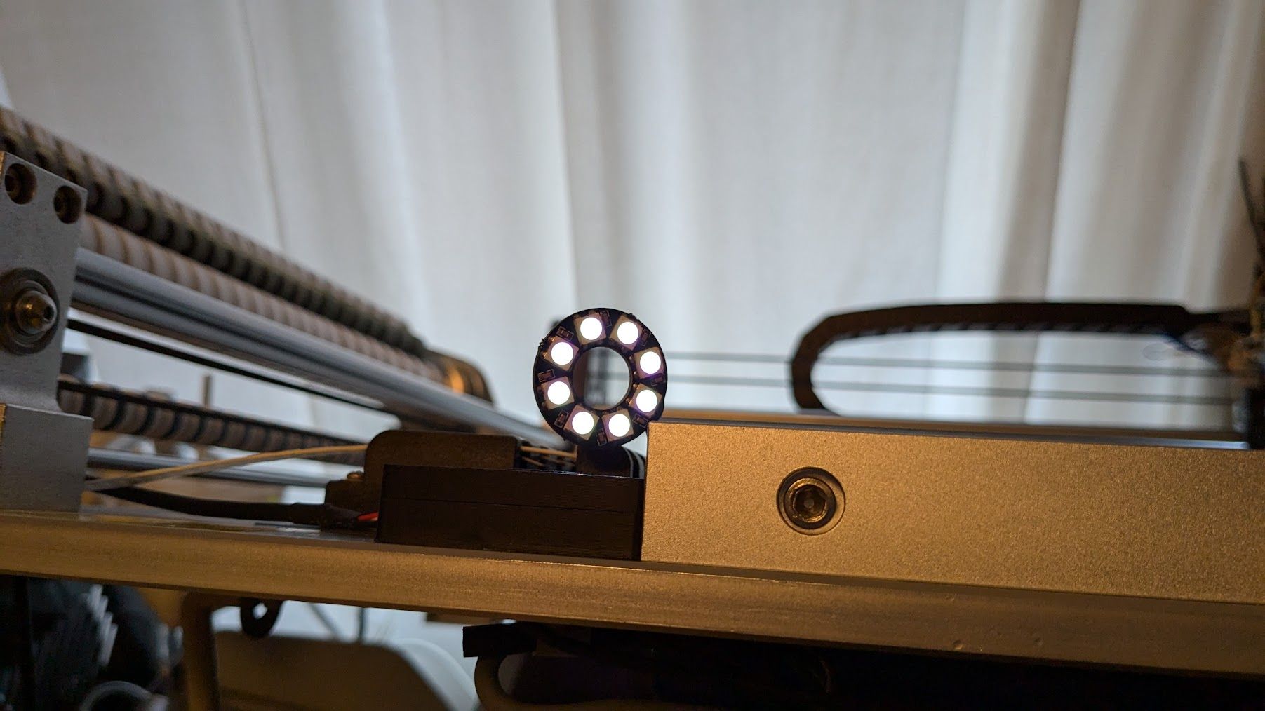
@tecno Do all 8 LEDs work now, and are controllable?
RGB LEDs aren't the best for white light. You'll have to play around with the levels in M150 for R, U (for green) and B, and brightness (P) to get close to what you want. If it's mostly white you want, you probably should have got RGBW, or just white, LEDs.
Ian
Bed-slinger - Mini5+ WiFi/1LC | RRP Fisher v1 - D2 WiFi | Polargraph - D2 WiFi | TronXY X5S - 6HC/Roto | CNC router - 6HC | Tractus3D T1250 - D2 Eth
-
@droftarts
Yes all 8 workI am aware that I can not get perfect greyscale with RGB. Hard to find 8leds RGBW that fits.
Thank you very much for your kind help Ian, I owe you a pint or two
")
I am sure more questions will arise
Cheers
Bengt -
-
@tecno said in 6XD I/O >> Issue solved:
;***Outputs
M950 P0 C"out0" ; Q500 ;#1 Nozzle Vacuum
M950 P1 C"out1" ; Q500 ;#2 Nozzle Vacuum
M950 P2 C"out2" ; Q500 ;Drag PIN Actuator
M950 P3 C"out3" ; Q500 ;ENA Nozzle 1/2 Up
M950 P4 C"out4" ; Q500 ;Xross cursor
M950 P5 C"out5" ; Q500 ;LED light x
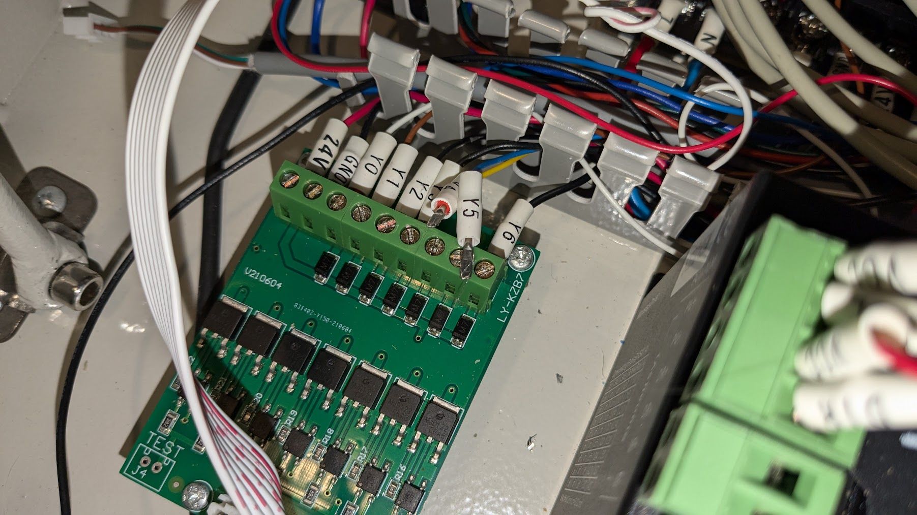
M950 P6 C"out6" ; Q500 ;Vacuum powerHave problem with Outputs 4 and 5. can not switch off. Any advice is appreciated-
Off=1.4V On=1.3V all other Off 24V On 0V
-
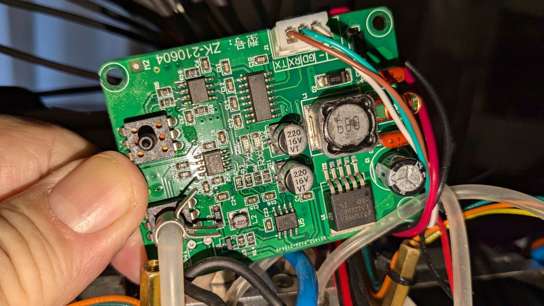
Is this something we can get working?
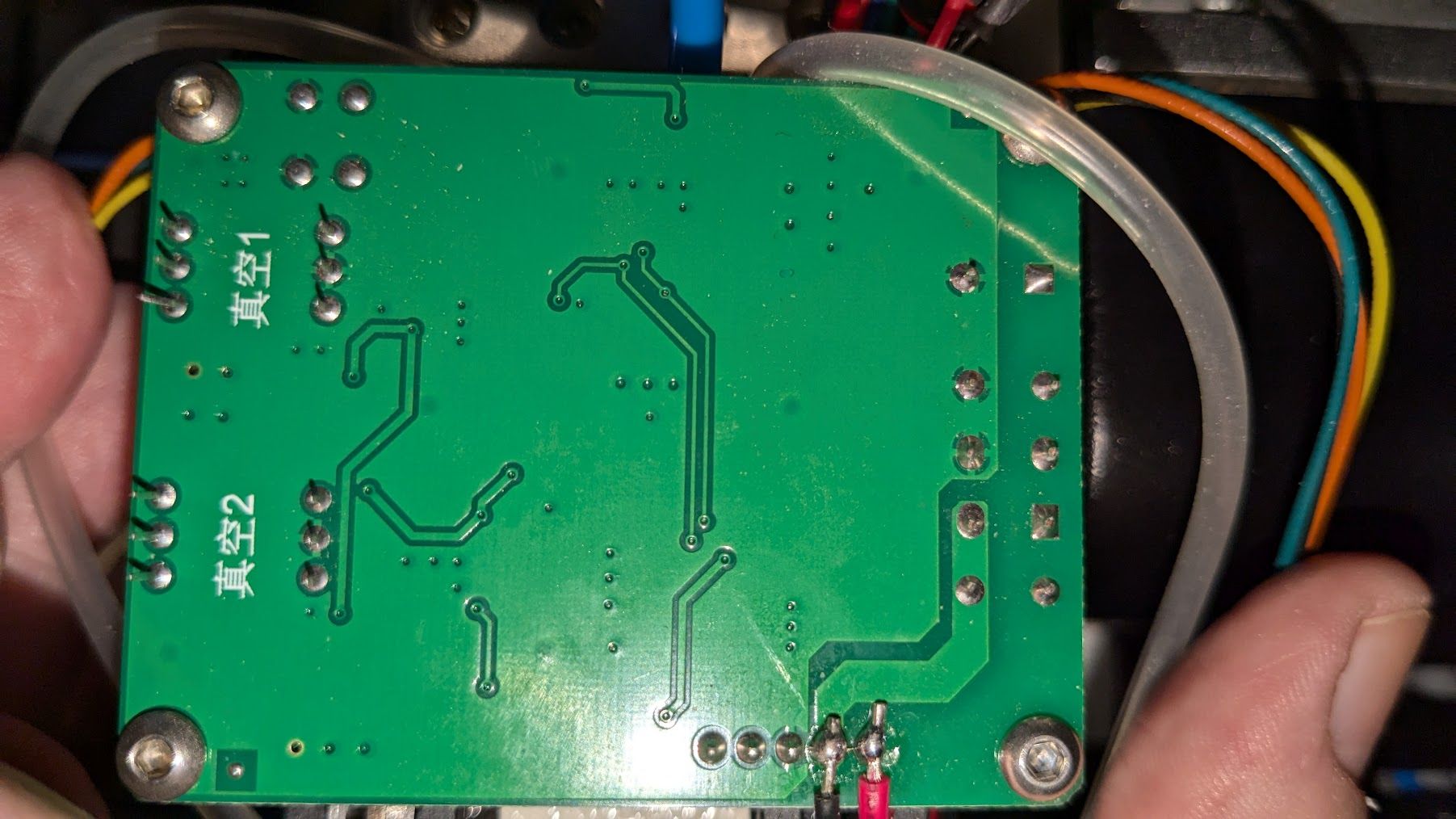
There is a cable with RX/TX/GND for the old controller. Two chips for vacuum measurement.
Cheers
Bengt -
@tecno said in 6XD I/O >> Issue solved:
Have problem with Outputs 4 and 5. can not switch off. Any advice is appreciated-
Off=1.4V On=1.3V all other Off 24V On 0VWas this working before? Have you fixed it? Sounds more like a wiring problem.
Is this something we can get working?
There is a cable with RX/TX/GND for the old controller. Two chips for vacuum measurement.What chip is it? You need to find out what signal it outputs, and what signal it expects. If it outputs an analog signal of 0-3.3V, you can probably set it up as an analogue sensor, or a digital sensor if it outputs an on/off signal.
Ian
Bed-slinger - Mini5+ WiFi/1LC | RRP Fisher v1 - D2 WiFi | Polargraph - D2 WiFi | TronXY X5S - 6HC/Roto | CNC router - 6HC | Tractus3D T1250 - D2 Eth
-
@droftarts
Hello Ian,These two worked OK with original controller, never got them working with 6XD.
Wires have been checked, but I have to measure continiuity once moore on out 4 and 5.Have to dismanlte the board and see what is on it.
Bengt
-
@tecno As they are both LEDs, are you supplying the 24V to the correct side of the LED? If not, the LEDs act as a diode, and don't let the power through.
Ian
Bed-slinger - Mini5+ WiFi/1LC | RRP Fisher v1 - D2 WiFi | Polargraph - D2 WiFi | TronXY X5S - 6HC/Roto | CNC router - 6HC | Tractus3D T1250 - D2 Eth
-
@droftarts
Cable is OK
Original connected to PSU, 12V for Cross and 5V for LED Light -
-
-
Regarding outputs 3 4 5 and 8 = not working at all!
Done following Change
;***Outputs
M950 P0 C"out0" ; Q500 ;#1 Nozzle Vacuum
M950 P1 C"out1" ; Q500 ;#2 Nozzle Vacuum
M950 P2 C"out2" ; Q500 ;Drag PIN Actuator
M950 P3 C"out3" ; Q500 ;ENA Nozzle 1/2 Up
;M950 P4 C"out4" ; Q500 ;Xross cursor
;M950 P5 C"out5" ; Q250 ;LED light
M950 P6 C"out6" ; Q500 ;Vacuum power
M950 P7 C"out7" ; Q500 ;Xross cursor
M950 P8 C"out8" ; Q500 ;LED lightTested first to move #4 to #7 and voila the xross cursor works with on and off.
So next #5 to #8 = NO GO
Changed #8 to #7 and the LED Lighting works.So now it is time to get this 6XD on WARANTY A S A P
Cheers
Bengt -
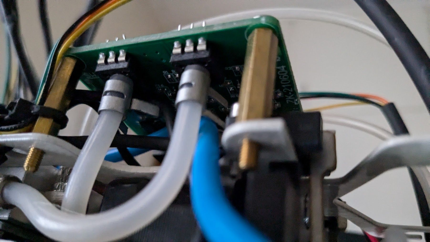
@tecno I suggest that you test the outputs on the actual 6XD. In all the previous 100+ messages in this thread, the fault has NOT been the 6XD, it's been the wiring. I assume that you have tested this by moving connections on this switching board, rather than testing the outputs on the 6XD:
There's a ribbon cable between the 6XD and that board. Have you tested the continuity of that? Have you tested that there are no failed components on that expansion board on these lines? After all the previous issues, I very much doubt it's an issue with the 6XD.
Ian
Bed-slinger - Mini5+ WiFi/1LC | RRP Fisher v1 - D2 WiFi | Polargraph - D2 WiFi | TronXY X5S - 6HC/Roto | CNC router - 6HC | Tractus3D T1250 - D2 Eth
-
@droftarts said in 6XD I/O >> Issue solved:
rather than testing the outputs on the 6XD:
All testing is on 6XD
The picture was to clarify port 4/5 to be the only way to switch off 4 and 5 loosening cables!
Pls explain why #8 works on #7 if it is as you claim to cabling issue!
Far too many issues points to a faulty 6XD.
Been setting up 4 machines with Mini 5+ and this one is giving one more gray hair! -
@tecno Every issue so far has been fixed, and has not been the fault of the 6XD. As for grey hair, you've given me plenty.
Have you checked the macros or commands you use to turn the outputs on and off refer to the correct pin?
I need to see how you're testing the outputs on the 6XD. Ideally, with a multimeter, test for voltage between the V_OUTLC# pin and the out#- pin, of each output. You should get no voltage when it's turned off, and should read the voltage of the V_OUTLC# when turned on. Repeat for all out# pins.
You should do this from a fresh restart, so the config.g is applied. Note that you currently have out4 and out5 commented out.
If there is an output that is not working, please post the full config.g that you used to test, and post the macros or commands you are using to turn these on and off. Also post a good image of the area around the fan outputs, which should show if any of the MOSFETs that control the out#- pins has been damaged.
Ian
Bed-slinger - Mini5+ WiFi/1LC | RRP Fisher v1 - D2 WiFi | Polargraph - D2 WiFi | TronXY X5S - 6HC/Roto | CNC router - 6HC | Tractus3D T1250 - D2 Eth
-
@droftarts
Nice with grey hair")
Yes all macros checked as regards command and pin#
M42 P3 S0
M42 P3 S1M42 P4 S0
M42 P4 S1M42 P5 S0
M42 P5 S1Tested with DMM and 3-5 works as you describe BUT connecting LED Light on say #5 it is permanently ON so as I see it there is something wrong. Connecting the LED Light to output 7 or 8 I can switch on and off.
Cheers
Bengt -
@tecno Those results don't make much sense. You said out4- and out5- don't switch off, and out8- doesn't switch on.
I think you're saying the results of your testing are:
- Multimeter test: out3-, out4-, out5- test correctly. Do out1-, out2-, out6-, out7-, out8- respond correctly? I thought out8 was the problem?
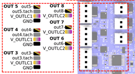
- LED test: out5- is permanently on. out7- and out8- test correctly. What about the rest? How are you connecting the LED? Between a V+ pin (whatever voltage the LED takes) and the out#- pin?
So out5- is the only one you tested with both tests? And it works okay with the multimeter test, but not the LED test?
Please post a picture of how you're testing with the LED, on a pin that's not working, so I can see the setup.
Please post your config.g, and all the macros you are using to turn the outputs on and off.Ian
Bed-slinger - Mini5+ WiFi/1LC | RRP Fisher v1 - D2 WiFi | Polargraph - D2 WiFi | TronXY X5S - 6HC/Roto | CNC router - 6HC | Tractus3D T1250 - D2 Eth
-
Outputs 0 1 2 6 7 8 OK
Outputs 3 4 5 the Led light is not controllable and always on.
config.txt macroszip.txt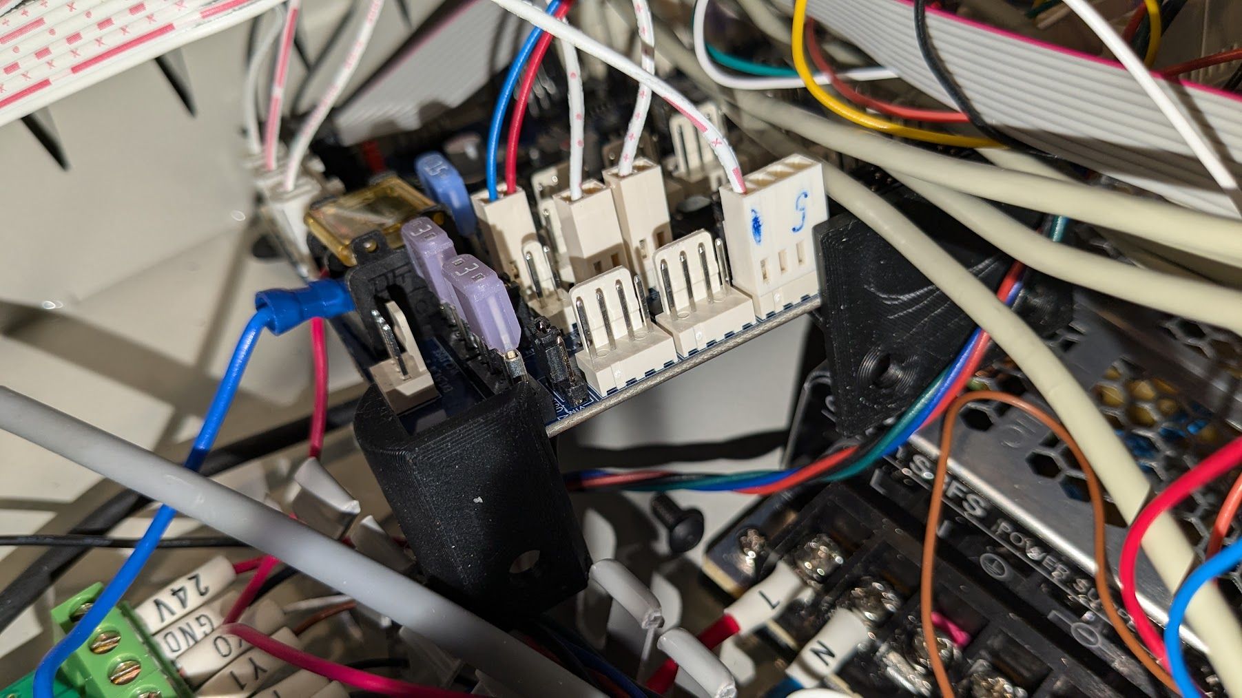
-
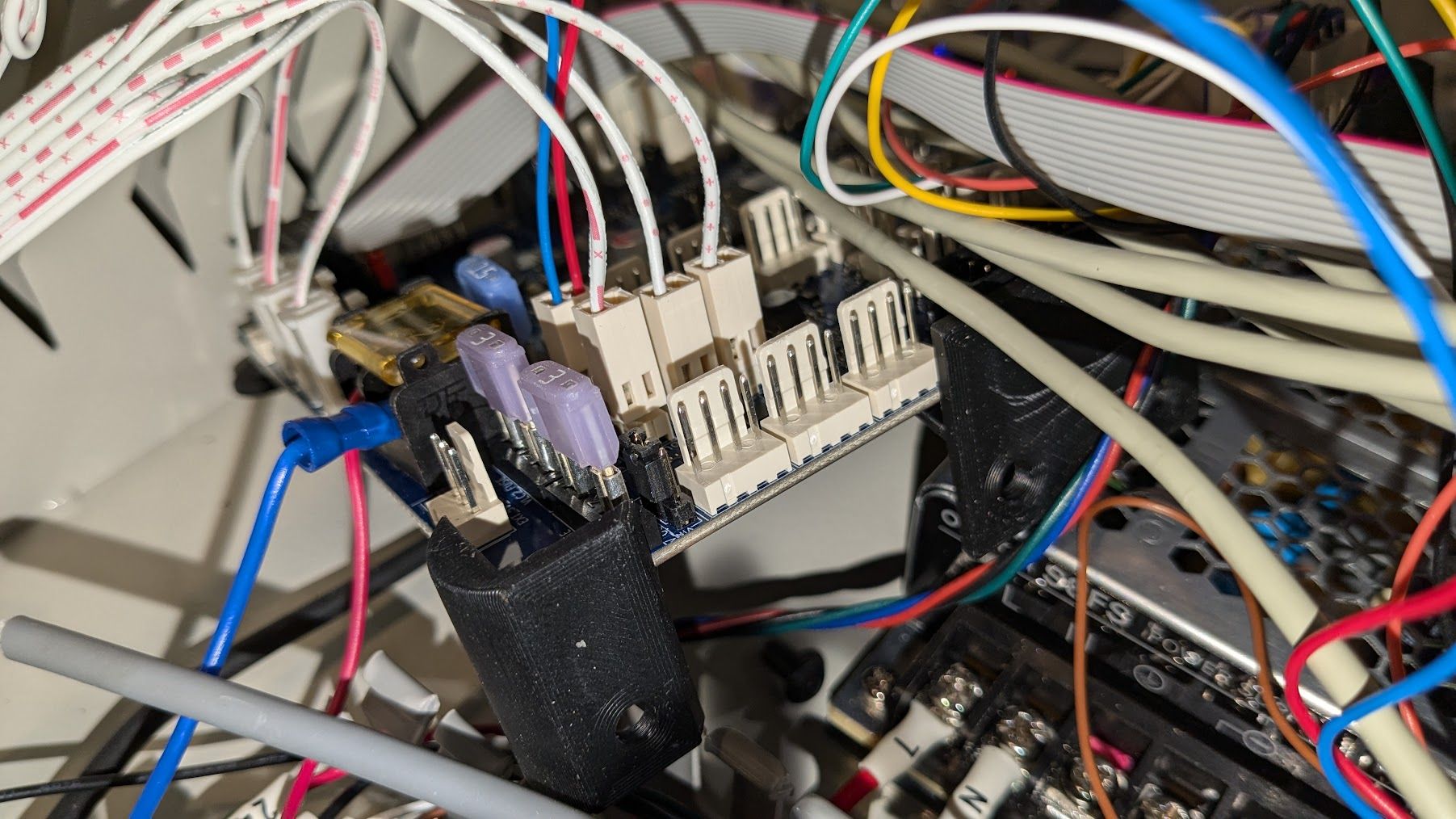
@tecno So in the first picture the LED doesn't work, connected to out3-, but in the second picture it does work, connected to out8-?
And you're not directly connecting an LED, you're still using the breakout board?
Ian
Bed-slinger - Mini5+ WiFi/1LC | RRP Fisher v1 - D2 WiFi | Polargraph - D2 WiFi | TronXY X5S - 6HC/Roto | CNC router - 6HC | Tractus3D T1250 - D2 Eth
-
3 4 5 behave the same. Does this anything with V_OUTLC1 and V_OUTLC2 to do?