Duet3D Logo Duet3D
    • Tags
    • Documentation
    • Order
    • Register
    • Login

    6XD I/O >> Issue solved

    Scheduled Pinned Locked Moved
    Duet Hardware and wiring
    4
    121
    5.3k
    Loading More Posts
    • Oldest to Newest
    • Newest to Oldest
    • Most Votes
    Reply
    • Reply as topic
    Log in to reply
    This topic has been deleted. Only users with topic management privileges can see it.
    • tecnoundefined
      tecno @tecno
      last edited by

      @droftarts

      Here pics of vacuum sensors = no labels

      PXL_20240930_124533812.jpg PXL_20240930_124257385.jpg

      tecnoundefined 2 Replies Last reply Reply Quote 0
      • tecnoundefined
        tecno @tecno
        last edited by

        @dc42 @droftarts

        Regarding outputs 3 4 5 and 8 = not working at all!

        Done following Change
        ;***Outputs
        M950 P0 C"out0" ; Q500 ;#1 Nozzle Vacuum
        M950 P1 C"out1" ; Q500 ;#2 Nozzle Vacuum
        M950 P2 C"out2" ; Q500 ;Drag PIN Actuator
        M950 P3 C"out3" ; Q500 ;ENA Nozzle 1/2 Up
        ;M950 P4 C"out4" ; Q500 ;Xross cursor
        ;M950 P5 C"out5" ; Q250 ;LED light
        M950 P6 C"out6" ; Q500 ;Vacuum power
        M950 P7 C"out7" ; Q500 ;Xross cursor
        M950 P8 C"out8" ; Q500 ;LED light

        Tested first to move #4 to #7 and voila the xross cursor works with on and off.
        So next #5 to #8 = NO GO
        Changed #8 to #7 and the LED Lighting works.

        So now it is time to get this 6XD on WARANTY A S A P

        Cheers
        Bengt

        droftartsundefined 1 Reply Last reply Reply Quote 0
        • droftartsundefined
          droftarts administrators @tecno
          last edited by

          @tecno I suggest that you test the outputs on the actual 6XD. In all the previous 100+ messages in this thread, the fault has NOT been the 6XD, it's been the wiring. I assume that you have tested this by moving connections on this switching board, rather than testing the outputs on the 6XD:

          alt text

          There's a ribbon cable between the 6XD and that board. Have you tested the continuity of that? Have you tested that there are no failed components on that expansion board on these lines? After all the previous issues, I very much doubt it's an issue with the 6XD.

          Ian

          Bed-slinger - Mini5+ WiFi/1LC | RRP Fisher v1 - D2 WiFi | Polargraph - D2 WiFi | TronXY X5S - 6HC/Roto | CNC router - 6HC | Tractus3D T1250 - D2 Eth

          tecnoundefined 1 Reply Last reply Reply Quote 0
          • tecnoundefined
            tecno @droftarts
            last edited by tecno

            @droftarts said in 6XD I/O >> Issue solved:

            rather than testing the outputs on the 6XD:

            All testing is on 6XD

            The picture was to clarify port 4/5 to be the only way to switch off 4 and 5 loosening cables!

            Pls explain why #8 works on #7 if it is as you claim to cabling issue!

            Far too many issues points to a faulty 6XD.
            Been setting up 4 machines with Mini 5+ and this one is giving one more gray hair!

            droftartsundefined 1 Reply Last reply Reply Quote 0
            • droftartsundefined
              droftarts administrators @tecno
              last edited by

              @tecno Every issue so far has been fixed, and has not been the fault of the 6XD. As for grey hair, you've given me plenty.

              Have you checked the macros or commands you use to turn the outputs on and off refer to the correct pin?

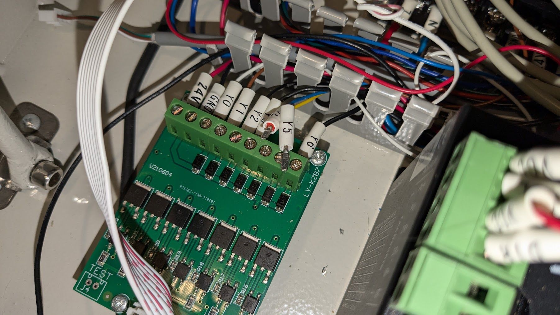
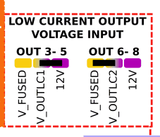
              I need to see how you're testing the outputs on the 6XD. Ideally, with a multimeter, test for voltage between the V_OUTLC# pin and the out#- pin, of each output. You should get no voltage when it's turned off, and should read the voltage of the V_OUTLC# when turned on. Repeat for all out# pins.

              c629310e-5686-4f09-b75a-7633e6053d6a-image.png

              You should do this from a fresh restart, so the config.g is applied. Note that you currently have out4 and out5 commented out.

              If there is an output that is not working, please post the full config.g that you used to test, and post the macros or commands you are using to turn these on and off. Also post a good image of the area around the fan outputs, which should show if any of the MOSFETs that control the out#- pins has been damaged.

              Ian

              Bed-slinger - Mini5+ WiFi/1LC | RRP Fisher v1 - D2 WiFi | Polargraph - D2 WiFi | TronXY X5S - 6HC/Roto | CNC router - 6HC | Tractus3D T1250 - D2 Eth

              tecnoundefined 1 Reply Last reply Reply Quote 0
              • tecnoundefined
                tecno @droftarts
                last edited by

                @droftarts
                Nice with grey hair 😉

                Yes all macros checked as regards command and pin#
                M42 P3 S0
                M42 P3 S1

                M42 P4 S0
                M42 P4 S1

                M42 P5 S0
                M42 P5 S1

                Tested with DMM and 3-5 works as you describe BUT connecting LED Light on say #5 it is permanently ON so as I see it there is something wrong. Connecting the LED Light to output 7 or 8 I can switch on and off.

                Cheers
                Bengt

                droftartsundefined 1 Reply Last reply Reply Quote 0
                • droftartsundefined
                  droftarts administrators @tecno
                  last edited by

                  @tecno Those results don't make much sense. You said out4- and out5- don't switch off, and out8- doesn't switch on.

                  I think you're saying the results of your testing are:

                  • Multimeter test: out3-, out4-, out5- test correctly. Do out1-, out2-, out6-, out7-, out8- respond correctly? I thought out8 was the problem?
                  • LED test: out5- is permanently on. out7- and out8- test correctly. What about the rest? How are you connecting the LED? Between a V+ pin (whatever voltage the LED takes) and the out#- pin?

                  So out5- is the only one you tested with both tests? And it works okay with the multimeter test, but not the LED test?

                  Please post a picture of how you're testing with the LED, on a pin that's not working, so I can see the setup.
                  Please post your config.g, and all the macros you are using to turn the outputs on and off.

                  Ian

                  Bed-slinger - Mini5+ WiFi/1LC | RRP Fisher v1 - D2 WiFi | Polargraph - D2 WiFi | TronXY X5S - 6HC/Roto | CNC router - 6HC | Tractus3D T1250 - D2 Eth

                  tecnoundefined 1 Reply Last reply Reply Quote 0
                  • tecnoundefined
                    tecno @droftarts
                    last edited by droftarts

                    @droftarts

                    Outputs 0 1 2 6 7 8 OK
                    Outputs 3 4 5 the Led light is not controllable and always on.
                    config.txt macroszip.txt

                    PXL_20241001_154645609.jpg PXL_20241001_154303359.jpg

                    droftartsundefined 1 Reply Last reply Reply Quote 0
                    • droftartsundefined
                      droftarts administrators @tecno
                      last edited by droftarts

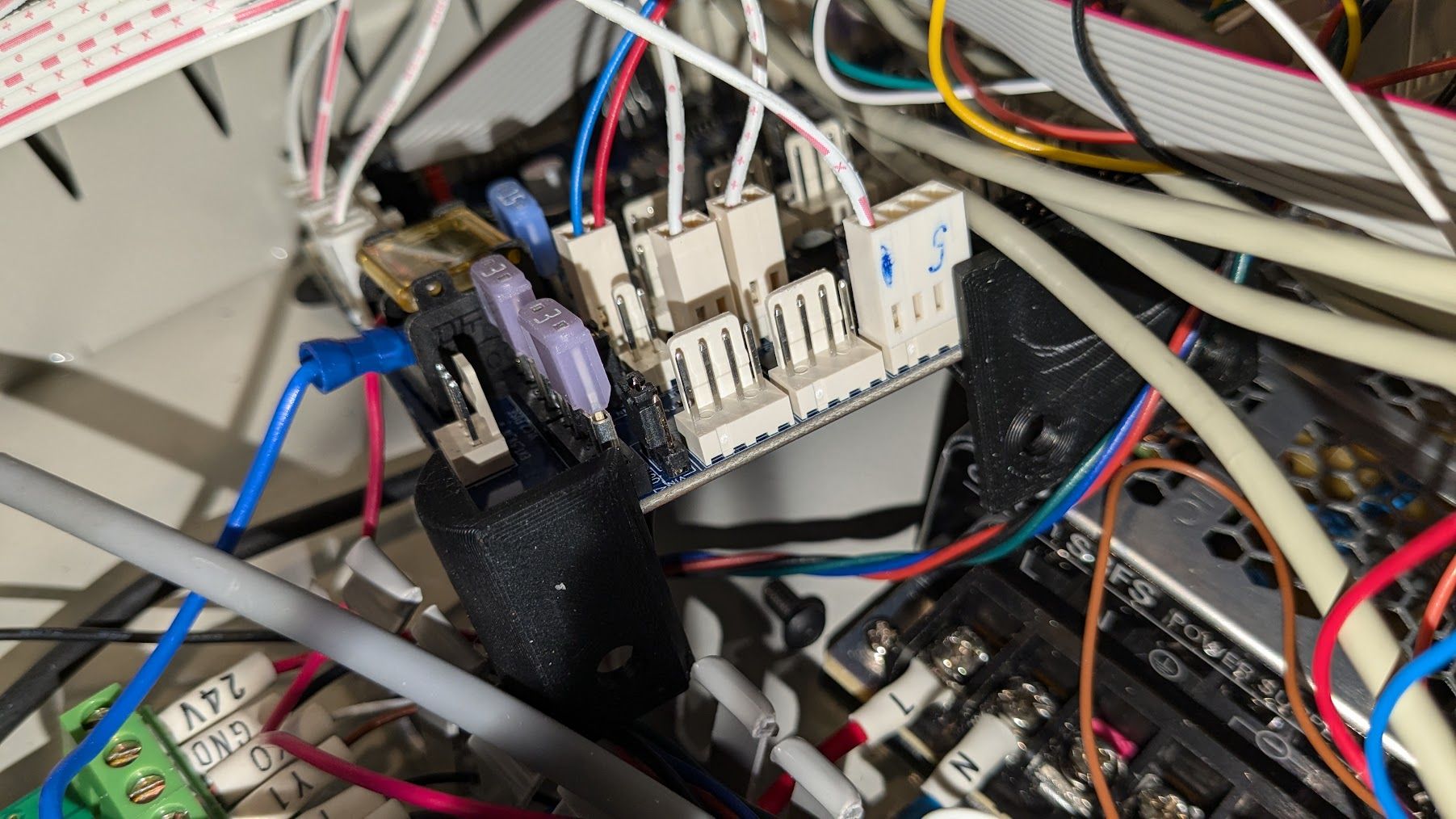
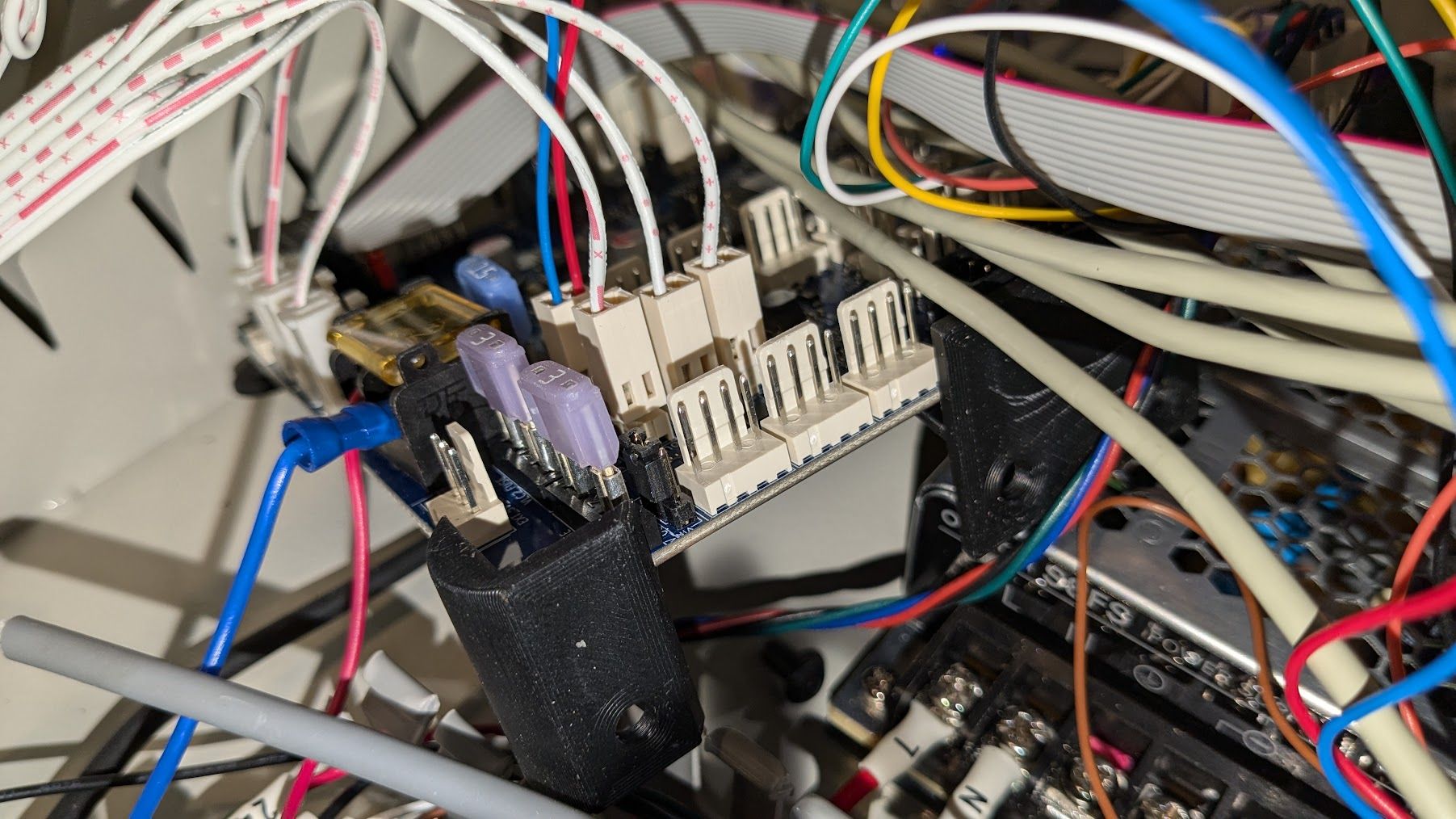
                      @tecno So in the first picture the LED doesn't work, connected to out3-, but in the second picture it does work, connected to out8-?

                      And you're not directly connecting an LED, you're still using the breakout board?

                      Ian

                      Bed-slinger - Mini5+ WiFi/1LC | RRP Fisher v1 - D2 WiFi | Polargraph - D2 WiFi | TronXY X5S - 6HC/Roto | CNC router - 6HC | Tractus3D T1250 - D2 Eth

                      tecnoundefined 2 Replies Last reply Reply Quote 0
                      • tecnoundefined
                        tecno @droftarts
                        last edited by

                        @droftarts

                        3 4 5 behave the same. Does this anything with V_OUTLC1 and V_OUTLC2 to do?

                        tecnoundefined 1 Reply Last reply Reply Quote 0
                        • tecnoundefined
                          tecno @droftarts
                          last edited by

                          @droftarts

                          Not a breakout board.

                          1 Reply Last reply Reply Quote 0
                          • tecnoundefined
                            tecno @tecno
                            last edited by tecno

                            @tecno

                            Does this anything with V_OUTLC1 and V_OUTLC2 to do?

                            YES IT DOES !!

                            tecnoundefined droftartsundefined 2 Replies Last reply Reply Quote 0
                            • tecnoundefined
                              tecno @tecno
                              last edited by

                              @dc42 @droftarts

                              Possible to concentrate on VACUUM sensors?

                              1 Reply Last reply Reply Quote 0
                              • droftartsundefined
                                droftarts administrators @tecno
                                last edited by

                                @tecno said in 6XD I/O >> Issue solved:

                                Does this anything with V_OUTLC1 and V_OUTLC2 to do?

                                YES IT DOES !!

                                Care to explain? I didn't even think you were using the V_OUTLC pins on the fan headers.

                                So they are all working now?

                                Ian

                                Bed-slinger - Mini5+ WiFi/1LC | RRP Fisher v1 - D2 WiFi | Polargraph - D2 WiFi | TronXY X5S - 6HC/Roto | CNC router - 6HC | Tractus3D T1250 - D2 Eth

                                tecnoundefined 1 Reply Last reply Reply Quote 0
                                • tecnoundefined
                                  tecno @droftarts
                                  last edited by

                                  @droftarts

                                  As 6-8 works with V_OUTLC2 I tried to same setting for 3-5 and now it works.
                                  9ca9f618-db6c-4255-a4bc-935f06881bce-image.png

                                  Cheers
                                  Bengt

                                  droftartsundefined 1 Reply Last reply Reply Quote 0
                                  • droftartsundefined
                                    droftarts administrators @tecno
                                    last edited by droftarts

                                    @tecno said in 6XD I/O >> Issue solved:

                                    As 6-8 works with V_OUTLC2 I tried to same setting for 3-5 and now it works.

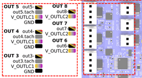
                                    I did wonder about that myself, but didn't think the voltage on V_OUTLC1 or 2 would matter. However, looking at the schematic of the 6XD, it does:
                                    563b65d1-25e4-4153-a6b6-6570b768ddb9-image.png

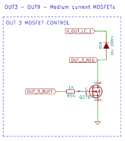
                                    As the LEDs connected to OUT3_NEG are powered from 24V, but VOUTLC1 was jumpered to 12V, then the LEDs will get around 12V even when the port is turned off, which is why they stayed lit. I'll have to remember that. Presumably you jumpered both of them to V-FUSED, which is 24V?

                                    Anyway, another problem resolved without recourse to a warranty replacement (which would have exhibited the same problem)!

                                    Ian

                                    Bed-slinger - Mini5+ WiFi/1LC | RRP Fisher v1 - D2 WiFi | Polargraph - D2 WiFi | TronXY X5S - 6HC/Roto | CNC router - 6HC | Tractus3D T1250 - D2 Eth

                                    tecnoundefined 1 Reply Last reply Reply Quote 0
                                    • tecnoundefined
                                      tecno @droftarts
                                      last edited by

                                      @droftarts said in 6XD I/O >> Issue solved:

                                      Anyway, another problem resolved without recourse to a warranty replacement (which would have exhibited the same problem)!

                                      I am happy as well.

                                      /Bengt

                                      1 Reply Last reply Reply Quote 0
                                      • tecnoundefined
                                        tecno @tecno
                                        last edited by

                                        @tecno said in 6XD I/O >> Issue solved:

                                        @droftarts

                                        Here pics of vacuum sensors = no labels

                                        PXL_20240930_124533812.jpg PXL_20240930_124257385.jpg

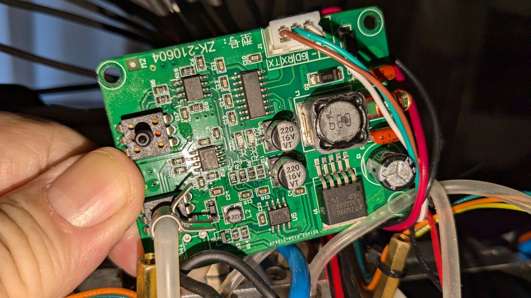
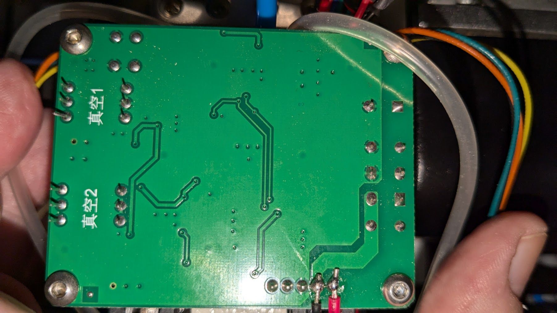
                                        This is what I have found

                                        MPS20N0040D-D Sphygmomanometer Dip Air Pressure Sensor Module 0-40kPa DIP-6

                                        [https://vi.aliexpress.com/item/1005004022663794.html?src=google&src=google&albch=shopping&acnt=298-731-3000&isdl=y&slnk=&plac=&mtctp=&albbt=Google_7_shopping&aff_platform=google&aff_short_key=UneMJZVf&gclsrc=aw.ds&albagn=888888&ds_e_adid=&ds_e_matchtype=&ds_e_device=c&ds_e_network=x&ds_e_product_group_id=&ds_e_product_id=en1005004022663794&ds_e_product_merchant_id=109387757&ds_e_product_country=SE&ds_e_product_language=en&ds_e_product_channel=online&ds_e_product_store_id=&ds_url_v=2&albcp=21634419038&albag=&isSmbAutoCall=false&needSmbHouyi=false&gad_source=1&gclid=Cj0KCQjw3vO3BhCqARIsAEWblcBENDN27oxA7msLr5_lLmacaCHv5tt1BCNc5EVKpbXMww9pwTqv4d0aAvlFEALw_wcB&gatewayAdapt=glo2vnm](link url)

                                        droftartsundefined 1 Reply Last reply Reply Quote 0
                                        • droftartsundefined
                                          droftarts administrators @tecno
                                          last edited by

                                          @tecno That board is effectively a 'black box'. You could try powering it up, and see what data comes out of RX/TX, but I think it's going to be difficult to integrate, and easiest to just replace.

                                          Google-ing that pressure sensor shows it on a breakout board that can connect to an Arduino: https://makersportal.com/shop/mps20n0040d-ported-pressure-sensor
                                          The output is an analogue 0-5V, so would need to be converted to 0-3.3V to be read by a Duet input. Fortunately this is quite easy to do with a voltage divider circuit, eg https://randomnerdtutorials.com/how-to-level-shift-5v-to-3-3v/. Then define it as a "linear-analog" sensor in M308.

                                          Google-ing "ported pressure sensor" shows that Adafruit do one that uses I2C: https://www.adafruit.com/product/3965
                                          I haven't looks closely, but this might be simple to integrate using M260. Don't use long cables with I2C, it's quite susceptible to noise.

                                          Sparkfun also do one: https://www.sparkfun.com/products/16476. Other ported pressure sensors may be available.

                                          Ian

                                          Bed-slinger - Mini5+ WiFi/1LC | RRP Fisher v1 - D2 WiFi | Polargraph - D2 WiFi | TronXY X5S - 6HC/Roto | CNC router - 6HC | Tractus3D T1250 - D2 Eth

                                          tecnoundefined 1 Reply Last reply Reply Quote 1
                                          • tecnoundefined
                                            tecno @droftarts
                                            last edited by

                                            @droftarts
                                            The board was working OK with original controller.
                                            The RX/TX signals are 5V on this board, I have bi-dir levelconverter.

                                            Is this the correct way to setup a second com port?

                                            ;***Serial Setup

                                            M575 P1 B57600 S1

                                            M575 P2 B9600 C"io_8" S7

                                            Cheers
                                            Bengt

                                            droftartsundefined 1 Reply Last reply Reply Quote 0
                                            • First post
                                              Last post
                                            Unless otherwise noted, all forum content is licensed under CC-BY-SA