Sovol SV08 Multiple Motion System Upgrade.
-
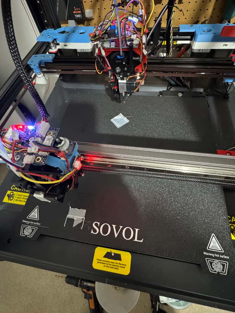
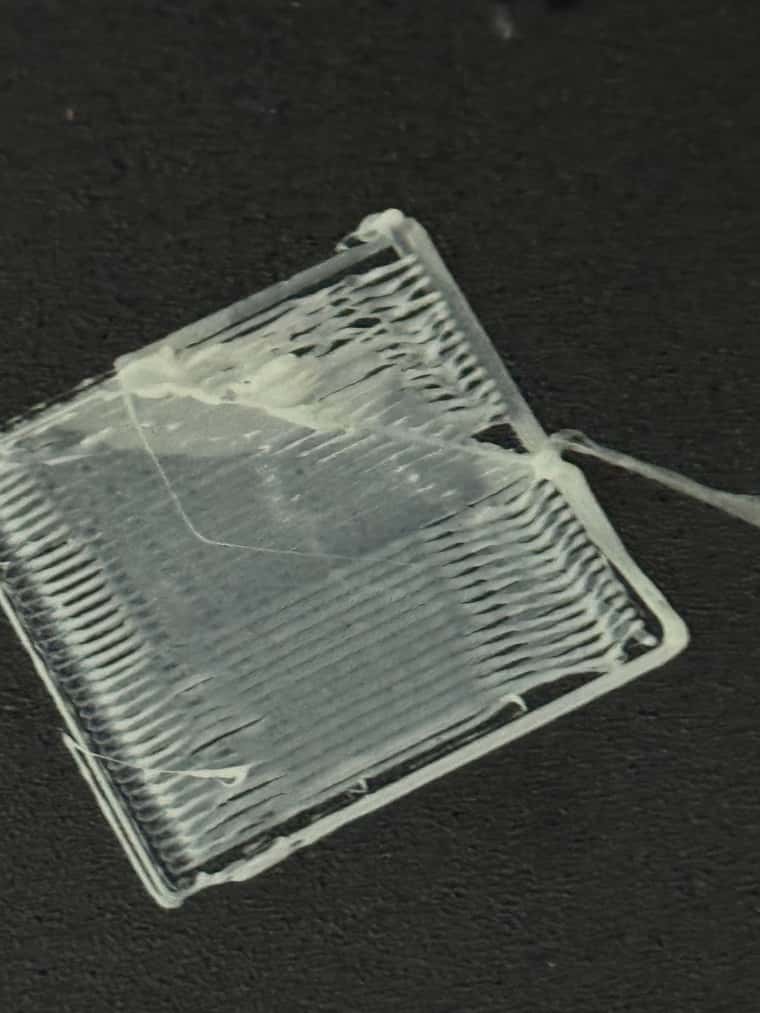
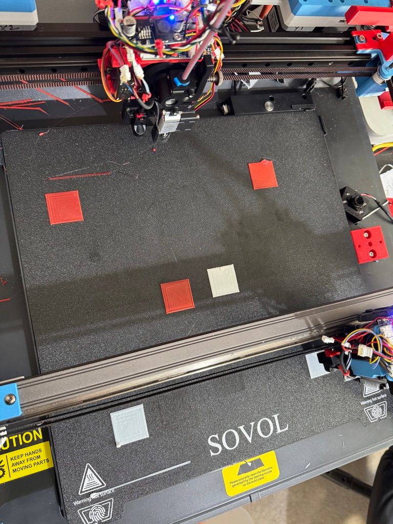
Horrible print quality I know because I didn't get the Z height quite right on the back gantry, plus it seems to have come loose a bit, plus had to comment out two lines of Gcode out due to Multiple Motion System gantry conflicts - which is why I think the front gantry print messed out.
Also had to manually set temperatures as haven't properly programmed them into the tool changing macros.
But still this is my first dual head, 4 segment print.
With the post processor created segment boundary crossing the 45 square on the back gantry.
-
@dwuk Still looking good for a first attempt. I guess you had mesh levelling off?
Maybe try to dial in each toolhead independently with unaltered single-head gcode. When both work OK on their own, let them cooperate. -
@o_lampe thanks. It was a pretty poor quality first test I agree, but it was nice to see both heads actually printing something independently.
The rear head had come quite loose which is why the lines are a bit curved- so I have upgraded the bolts that hold the two linear rails together.
Also I had specified ABS instead of PLA in the material profile in Orcaslicer which explains why the extruders kept wanting to go up to 260 and the bed was hotter than it usually is.
Will look at mesh levelling fairly soon.
Will do another attempt in the next couple of days once I have made some corrections to the parallel print gcode post processor.
Won't be able to get beyond layer2 though until I have resolved my RRF MMS M598 sync issue.
I tried working around it with conditional rrf gcode with loops and dwells - but haven't found a reliable way to get the motion systems to wait for each other yet.
-
@dwuk said in Sovol SV08 Multiple Motion System Upgrade.:
Also when you just use the button's to move the U & V - they don't react instantly - so I am wondering where there is some sort of comms issue in 3.6.0b4 - as I don't notice this in 3.5.4
There are known synchronisation issues in 3.6beta releases including beta 4 when a main board is used in expansion mode. These have now been resolved.
Duet WiFi hardware designer and firmware engineer
Please do not ask me for Duet support via PM or email, use the forum
http://www.escher3d.com, https://miscsolutions.wordpress.com -
@dc42 great - look forward to getting access to the fixed version.
The biggest issue that leaves me with is that I can't seem to get M598 to work in any version I have tried.
I am sending commands in the sequence
M596 P1
G1....setA
M596 P0
G1...setB
M598
G1...setC (with or without M596 P0)When SetB is faster than SetA - I am finding setC moves start before setA moves are complete -which is not the behaviour I was hoping for.
-
 undefined dwuk3d referenced this topic
-
@dc42 Update - solved my M598 not working issue hopefully.
So far (apart from the poor quality test print) I have been running all my tests with the gcode. M569/G1/M598 sequences in macro's - that I have been executing standalone.
I noticed that in the documentation it mentions something about macro's only using one stream.
Thought I would try downloading the macro, and then re-uploading it as a job.
Doing this completely changed the behaviour - and in my first few tests it looks like now the M598's seem to be doing what I wanted - i.e. Gantries waiting for each other, things that shouldn't be running in parallel waiting for each other.
So will change to using jobs rather than macro's for all of my future tests.
Also using this approach I have been able to get M597 to accept numbers as high as 30 without the motion all getting messed up - like it did in earlier tests when I went above 6.
However I am not sure whether this is due to the macro vs job differences, or the fact that my system is currently set as V3.6.0b4 on all boards (other than the Mini5+ - that is still on 3.5.4 due to the slow motion issue).
-
@dwuk said in Sovol SV08 Multiple Motion System Upgrade.:
I noticed that in the documentation it mentions something about macro's only using one stream.
Do you mean this setion? https://docs.duet3d.com/en/User_manual/RepRapFirmware/Multiple_motion_systems#macros-and-motion-systems
I'm not sure if this is changed behaviour between 3.5 and 3.6, or at least how it deals with multiple motion within macros may have changed, as you say it was working in 3.5. I'll check with @dc42.
Ian
Bed-slinger - Mini5+ WiFi/1LC | RRP Fisher v1 - D2 WiFi | Polargraph - D2 WiFi | TronXY X5S - 6HC/Roto | CNC router - 6HC | Tractus3D T1250 - D2 Eth
-
@droftarts Yes I think it was that section.
What I think is happening is if you run a macro from DWC then it seems to ignore M598's - this happens I think on 3.5.4 and 3.6.0b4. M596's work as expected though in this mode.
The difference I have noticed between 3.5.4 and 3.6.0b4 - is relating to releasing Axis.
In 3.5.4 Axis seem to not be held after M400's (or the ignored M598's I presume).Whereas with 3.6.0b4 I can't so far find a way of releasing an Axis once is has been allocated to motion system by a M596. Neither M598's run from DWC or from Jobs seem to release the Axis - which I am managing to work around for now by doing the homing within M596's.
But this will probably be a problem when I want to do things like layers with part IDEX duplicate mode and part independent Axis printing.
I haven't investigated M400s - but I suspect I have the same issue with them.
I am wondering whether I can work around it somehow by swapping motors between Axis,
-
Having quite a lot of trouble with getting parallel moves working - on 5.6.0b4
If I only have a small number of G1's then they run in parallel ok, but as soon as I introduce more than 5 moves then only the last 5 seem to run in parallel.
For example if I send 10 moves to motion system 0, plus 5 to motion system 1, then it seems that the motion system 1 moves will not start until there are only 5 moves left on the motion system 0 queue.
I have tried lots of combinations of P,R and S values M597 values on both queues - but it doesn't seem to make any difference to when the queue 1 start to run in parallel.
It also doesn't seem to be a speed or time related - because changing the speed of the last 5 moves in queue 0 also exhibits the same behaviour.
I guess I could do some complex processing on the two streams to work out their likely move times and then try and present them in tiny little blocks - but that is not the way I was expecting things to work.
What I have like to be able to do is ideally have a whole 'segment' (probably about 1/4 the size of the print bed) sent to motion system 0, in parallel to another 'segment' sent to motion system 1 - which could be 100s of G0/G1/G2/G3s running in parallel.
Have tried to understand the code - but it is quite complicated.
My only discoveries so far is that it looks like the M597 P value defaults to 60 on both queues - not 3 on queue1 as per documentation. Also I can't see anywhere that the S value is processed.
Example very simple job attached.
if move.axes[0].homed == false || move.axes[1].homed == false || move.axes[2].homed == false || move.axes[3].homed == false || move.axes[4].homed == false
  G28


T0

G1 Y20 X100 G5000
M400


M596 P0


G1 Y10 F500
G1 X100 F500
G1 Y20 F500
G1 X150 F500
G1 Y30 F500
G1 X160 F500
G1 Y40  F500
G1 X170 F500
G1 Y50 F500  ;First Parallel Move
G1 X180 F500
G1 Y60 F500
G1 X190 F500
G1 Y70 F500

M596 P1


G1 U100 F5000
G1 U200 F5000


M596 P0


G1 Y20 F10000
G1 Y50 F10000
G1 X200 F5000
G1 X300 F5000


M596 P1

G1 U120 F5000
G1 U200 F5000
G1 V300 F5000

M598
M400


M596 P0
I this example Gantry0 does the first 8 moves by itself, with gantry1 only starting to move in parallel to the last 5 moves. If I change the number of moves in the first block then the parallel start moves back or forward - so that only the last 5 moves are done in parallel.
The 2nd two small blocks of moves run in parallel ok.
-
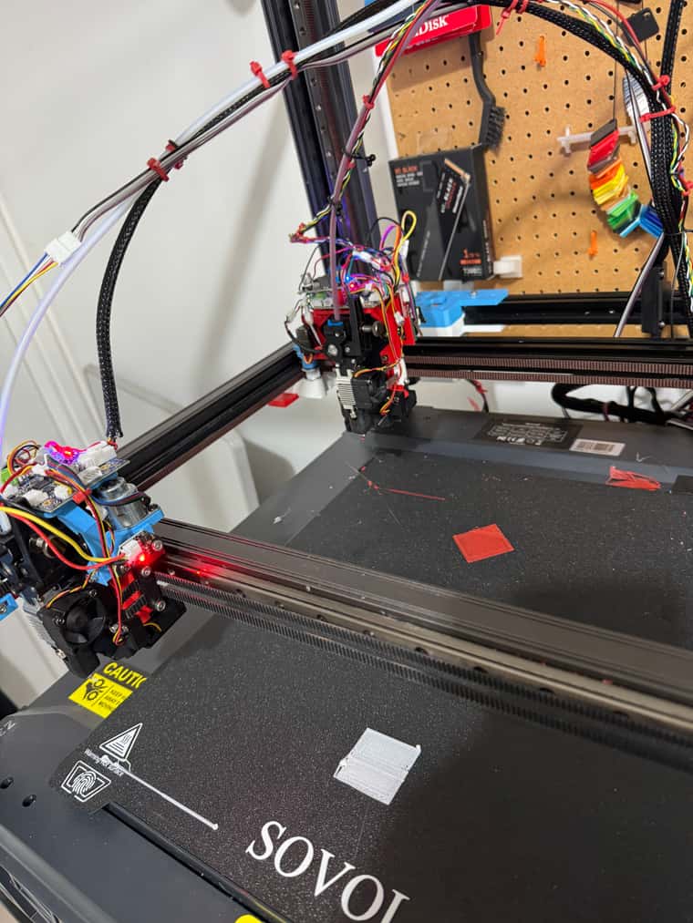
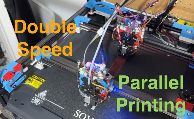
Demo of slightly parallel print.
https://youtube.com/shorts/02D4zS33ymk?si=yqVuzbFA2yzvwQvO
The red and white segments should be both printing at the same time - but as per 1m50s into video - the white only comes in about 5 moves from the end of the Red.
The GCODE file consisted for M569 P1, Red Segment 1, M569 P0, White Segment1 etc.
Work needed I know on parking and restart priming - but still fairly pleased with the slightly overlapping segments.
-
Update - found a command by looking at the RRF code - M606 S1.
This seems to be needed to get the parallel printing to work - it is not mentioned in the Multi Motion System documentation - but is in the Gcode dictionary.
I got a few out of memory errors and head crashes (update - this was due to me still trying to increase the queue sizes to 100 which is no longer required) so might need to refine homing - but did manage to get my gcode post-processed segmented print to run in parallel by adding this command to the top of the file.
But did manage to get some proper parallel printing going - see attached video.
-
Made quite a few improvements to Z height setting between the two gantries.
So far only using the two inductive problems - but will add in the front Gantry Voron Tap capability, plus the ball probe.
Also made a start on Z Hopping - initial Macro here.
;M800.g
if exists(param.P)
    if param.P == 0
        if exists(param.H)
            if param.H > 0
                M596 P0
                G90
                G1 H2 B0.8 F300
                M84 B ; Turn off IDLE current on B

            else
                M596 P0
                G90
                G1 H2 B0.4 F300
                M84 B ; Turn off IDLE current on B

        else
            echo "Hop parameter H missing"
    if param.P == 1
        if exists(param.H)
            if param.H > 0
                M280 P1 S60  ; Set Servo

            else
                M280 P1 S120  ; Set Servo

        else
            M42 P1 S0
At present I have a stepper on Axis B for the front gantry (P0) and a servo for the rear gantry (P1).
Not sure how well the servo movements will work with the motion queue - so lots of testing to do.
-
Having a bit of trouble getting a consistent first layer across both tools when I have tried a large single model printed by both print heads - so decided to start investigation mesh compensation.
First stage is probing the bed - I don't think it is too bad based on this initial test - I was expecting it to be worse than this.
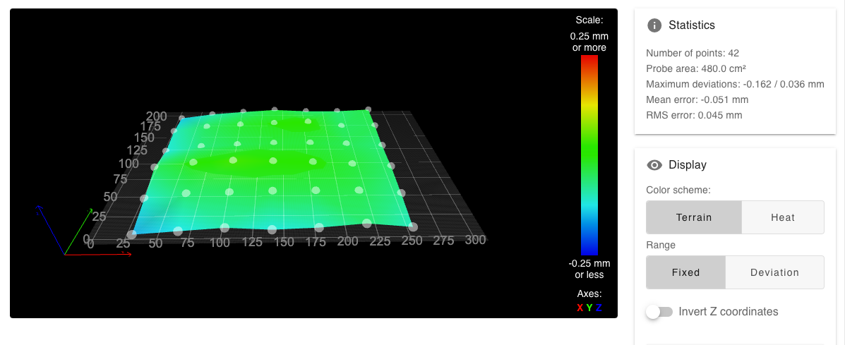
Because the mesh compensation in the firmware is not aware of my 'mini Z axis/ZHopper' - then I am going to have to do the mesh compensation off-line in a post processor.
I will have to split each long move into segments the size of the grid.
First thing I will do is just try and get printing working really well on the XY axis (without the ZHopper), but with mesh compensation on.
Will then investigate whether I can do anything with tool mapping - by switching the Z axis between the main gantry Z axis at layer changes, and within the layer my ZHop (B) Axis - to see if I can convince the firmware to apply the compensation to my miniZ axis instead of the real one.
If as I expect this doesn't work -
Then will try to get the same results with no mesh compensation on, but instead doing the compensation in a post processor - - that takes in the Gcode and the heightmap.csv - then replicates what is done in Move::ComputeHeightCorrection. - and then does actual moves using my B axis.
Then once I have got it working for the XY axis, I should be able to do the same for the UV axis, plus later the 2 other IDEX print heads.
-
Update - changed my probing approach and tried some prints with and without mesh levelling and didn't notice a lot of difference, so will leave it for now.
Managed to get a fairly good quality dual tool IDEX print working - see attached.
Just need to sort out oozing while tool is parked, and some sort of wiping.
Now moving on the Z Hoppers.
At present my XY Zhopper is attached the the Mini5+ board (with the UV Gantry) - which I expected to cause problems when using multiple motion systems - which it did.
So I have swapped one of the Z Motors over to the Mini5+, so that the Zhopper is on the main 6HC board.
Initial tests are showing better results - with the Z Hopper moving at the correct time in the sequence.
The Servo based Z Hopper is a bit of an issue too.
I was expecting to run it on Motion System 1 - with the UV axis - but I am finding the servo movements are not happening as expected, where as if I run the UV Axis and the Servo on Motion System 0 is seems to work better - so might have to operate in that way - will probably have to swap the rest of the Z Axis over to the Mini5+ too - so will use Motion System 0 for UVZ + Servo, and Motion System 1 for X,Y,B(Z Hopper).
I don't really need to run the Z in parallel so will what happens for a while leaving it spread across the two boards - as unfortunately the stepper connectors are different between the 6HC and Mini5+
-
Parallel printing working demo Video
Fully aligned - single object parallel print
With alignment using Ember Prototypes CXC
-
@dwuk said in Sovol SV08 Multiple Motion System Upgrade.:
I will have to split each long move into segments the size of the grid.
IMO, that won't be that easy. Mesh adjustment is continuous between grid points.
And for tool No2 you'd have to know where tool No1 is to compensate No2's adjustment accordingly. -
@o_lampe said in Sovol SV08 Multiple Motion System Upgrade.:
@dwuk said in Sovol SV08 Multiple Motion System Upgrade.:
I will have to split each long move into segments the size of the grid.
IMO, that won't be that easy. Mesh adjustment is continuous between grid points.
And for tool No2 you'd have to know where tool No1 is to compensate No2's adjustment accordingly.I'm thinking that if I do external adjustments I will get the printer to probe the mesh, but not enable mesh compensation of any print head - and would do all of the mesh adjustments manually.
Therefore in the example you gave Tool No1 would have its own independent adjustment (using the Z Hopper stepper), and therefore would not affect the adjustments that would need to be made for Tool No2 (using its Z hopper stepper) I think.
From looking at the code - it looks like long moves are segmented up for various reasons - including mesh compensation grid size - and then if mesh compensation is turned on it interpolates what the Z position of the moveTo point needs to be adjusted by - then effectively adds a Z up or down move to the XY move - which then I am guessing adds tiny linear steps to the Z move as moves between the two XY points.
Therefore in the case of my XYB and UVC design - I would only use Z for layer changes, with all other Zhops and mesh adjustments being done independently with the B and C Zhopper axis.
Every XY or UV move would where required firstly be segmented into grid size chunks, and then have a B or C move up or down added to every XY or UV move.
It may as you say be more complicated than this - but it should do something to help.
Once I have resolved my flushing/oozing issues will do some more tests to confirm where meshing issues show up, and then try to fix them with my proposed approach.
Once I get to IDEX I would have something like - with XxYBb UuVCc Z - where BbCc are the 4 Z Hoppers - which would all need to be added to the moves for manual meshing.
PS/ I think the Z hopper approach to small fast moves - rather than using the now quite heavy (and soon to be even heavier) Z gantry might end up working quite well.
-
Quite a frustrating day.
Hit an issue with Sensorless homing in motion System 1 on main 6HC board. But found that on 3.5.4 it is possible to release Axis from motion systems with this sequence - from the current motion system
T-1
M400 (or probably M598)So switched the axis between Motion system 0 and 1 to get the homing to work,
Made some good progress on flushing, but then hit an issue with speeds.
On 3.5.4 motion system 0 move speeds seem to match the GCODE/config.g ok - but on Motion System 1 they seem to be a lot faster - even on layer 1 - and the web interface doesn't report the speeds.
So switched to 3.6.0.rc1 to try and solve the speed issue.
The good news is that the Axis on the Mini5+ doesn't seem to be slow now - like it was on 3,6,0b4
On 3.6.0rc1 sensorless homing seems to work ok on motion system1 - but the problem with these versions is that it seems to be impossible to release an axis from a motion system once it has been used - including the first time - as per the @Alva thread.
Tried getting 3.6.0.rc1 homing macro's working - but it was getting steadily more complicated - especially with bed probing - where I need to specify Z,X & Y in the same command - but it won't let me - as they are stuck in separate motion systems after homing - so have switched back to 3.5.4 again for now
The only way I can think to get 3.6.0rc1 working for me is:
a) Switch XYZ to be back to all be on motion system 0 - and forget the servo based Z Hopping on the UV axis (which only works on Motion system 0).
b) Switch Bed probing over from the XYZ to UVZ Axis. -
@dwuk said in Sovol SV08 Multiple Motion System Upgrade.:
I would only use Z for layer changes, with all other Zhops and mesh adjustments being done independently with the B and C Zhopper axis.

That's what I proposed to implement in RRF while I played with the hashPrinter.I wonder if it's possible to use G10/G11 for FW-retraction with zHop in your case? You'd have to link it with your BbCc motors. @dc42 ?
-
@o_lampe Interesting - I hadn't thought about firmware retraction - its turned off in my printer profile - but if I turn it on - I get this as a typical sequence
G10 ; retract
;WIPE_START
G1 X140.121 Y84.188 E-.24
;WIPE_END
M486 S-1
M486 S1
G1 Z.6 F15000
G1 X152.303 Y279.456 Z.6
G1 Z.2
G11 ; unretract
I've created my own ZHOP command - M800 - I guess I could use being inside a G10/G11 pair to know to change the Z moves to my M800 commands.
I will also try just commenting out the Z moves (or turning off Z Hopping in the slicer), and try setting the Z axis to my B/C axis in the M563 tool definition as you suggest- and then specify Z Movement in my M207 to see what happens.
Will also try turning on meshing with my BC axis defined as Z to see if it does any auto adjustments using my axis, rather than the proper Z Axis.