Duet not connect in anyways - Clue: nozzle fan always on
-
@genioluiz7 Yes, that's correct. If you edited it on the SD card, that's all you need to do. If you edited config.g on your PC, then you need to copy it to the SD card. Then replace the SD card in the Duet and reset.
The config.g file is read by the Duet at start up. It shouldn't now try to turn on. Connect via USB and send M997 S1.
If the WiFi updates correctly, and sending M552 S1 turns it on (check with M122), then you will need to edit config.g to enable networking at start up, by removing the
;from the M552 S1 line.Ian
TronXY X5S with Duet 3 MB6HC and Roto toolboard : Cartesian bed-slinger with Duet 3 Mini 5+ WiFi and 1LC : RRP Fisher Delta v1 with Duet 2 Maestro : Polargraph with Duet 2 WiFi
-
@droftarts nothing. It didn't work. How we proceed now?
M997 S1
T0:20.6 /0.0 B:20.9 /0.0
Trying to connect at 230400 baud: failed
Trying to connect at 115200 baud: failed
Trying to connect at 74880 baud: failed
Trying to connect at 9600 baud: failed
Error: Installation failed due to comm write error
ok
M122
=== Diagnostics ===
RepRapFirmware for Duet 2 WiFi/Ethernet version 3.4.6 (2023-07-21 14:08:28) running on Duet WiFi 1.02 or later
Board ID: 0JD0M-9P6M2-NW4SN-6J1DG-3SD6J-TUT3L
Used output buffers: 1 of 26 (2 max)
=== RTOS ===
Static ram: 23896
Dynamic ram: 75148 of which 0 recycled
Never used RAM 13036, free system stack 193 words
Tasks: NETWORK(ready,26.2%,384) HEAT(notifyWait,0.0%,333) Move(notifyWait,0.0%,363) MAIN(running,73.2%,460) IDLE(ready,0.5%,30), total 100.0%
Owned mutexes: USB(MAIN)
=== Platform ===
Last reset 00:02:30 ago, cause: reset button or watchdog
Last software reset time unknown, reason: User, GCodes spinning, available RAM 9748, slot 2
Software reset code 0x0003 HFSR 0x00000000 CFSR 0x00000000 ICSR 0x0041f000 BFAR 0xe000ed38 SP 0x00000000 Task MAIN Freestk 0 n/a
Error status: 0x00
Aux0 errors 0,0,0
Step timer max interval 0
MCU temperature: min 29.7, current 34.6, max 34.9
Supply voltage: min 1.6, current 1.7, max 1.8, under voltage events: 0, over voltage events: 0, power good: no
Heap OK, handles allocated/used 0/0, heap memory allocated/used/recyclable 0/0/0, gc cycles 0
Events: 0 queued, 0 completed
Driver 0: ok, SG min n/a
Driver 1: ok, SG min n/a
Driver 2: ok, SG min n/a
Driver 3: ok, SG min n/a
Driver 4: ok, SG min n/a
Driver 5:
Driver 6:
Driver 7:
Driver 8:
Driver 9:
Driver 10:
Driver 11:
Date/time: 1970-01-01 00:00:00
Cache data hit count 4294967295
Slowest loop: 14.09ms; fastest: 0.14ms
I2C nak errors 0, send timeouts 0, receive timeouts 0, finishTimeouts 0, resets 0
=== Storage ===
Free file entries: 10
SD card 0 detected, interface speed: 20.0MBytes/sec
SD card longest read time 3.9ms, write time 0.0ms, max retries 0
=== Move ===
DMs created 83, segments created 0, maxWait 0ms, bed compensation in use: none, comp offset 0.000
=== MainDDARing ===
Scheduled moves 0, completed 0, hiccups 0, stepErrors 0, LaErrors 0, Underruns [0, 0, 0], CDDA state -1
=== AuxDDARing ===
Scheduled moves 0, completed 0, hiccups 0, stepErrors 0, LaErrors 0, Underruns [0, 0, 0], CDDA state -1
=== Heat ===
Bed heaters 0 -1 -1 -1, chamber heaters -1 -1 -1 -1, ordering errs 0
=== GCodes ===
Segments left: 0
Movement lock held by null
HTTP is idle in state(s) 0
Telnet is idle in state(s) 0
File is idle in state(s) 0
USB is ready with "M122" in state(s) 0
Aux is idle in state(s) 0
Trigger is idle in state(s) 0
Queue is idle in state(s) 0
LCD is idle in state(s) 0
Daemon is idle in state(s) 0
Autopause is idle in state(s) 0
Code queue is empty
=== Network ===
Slowest loop: 1001.24ms; fastest: 0.00ms
Responder states: HTTP(0) HTTP(0) HTTP(0) HTTP(0) FTP(0) Telnet(0)
HTTP sessions: 0 of 8
= WiFi =
Interface state: disabled
Module is disabled
Failed messages: pending 0, notready 0, noresp 0
Socket states: 0 0 0 0 0 0 0 0
ok -
@genioluiz7 I'm not sure. Try sending
M552 S0to put it in idle mode, thenM997 S1.If that doesn't work, I think whatever event caused the firmware to be deleted in the first place may have damaged the WiFi module. Looking back at the first M122 report you posted, it says:
Last software reset at 1988-01-29 20:06, reason: HardFault undefInstr, Platform spinning, available RAM 106152, slot 0We have found "HardFault undefInstr" (undefined instructions) are quite often associated with ESD (static discharge) events.
Ian
TronXY X5S with Duet 3 MB6HC and Roto toolboard : Cartesian bed-slinger with Duet 3 Mini 5+ WiFi and 1LC : RRP Fisher Delta v1 with Duet 2 Maestro : Polargraph with Duet 2 WiFi
-
@droftarts So, how can I verify this?
I saw during the tests that the blu led on the wifi module sometimes flashes. Maybe is a signal that it is still alive
There is somenthing else we can try to do? -
@genioluiz7 did you try using M997 S1 to reinstall the WiFi firmware?
Duet WiFi hardware designer and firmware engineer
Please do not ask me for Duet support via PM or email, use the forum
http://www.escher3d.com, https://miscsolutions.wordpress.com -
@dc42 yes I tried but nothing happened. What do you think?
-
@genioluiz7 I've read back through the forum thread, and it does seem that the WiFi module has failed. Because the firmware on the Duet was also erased, I'd suspect either a wiring short or ESD "static electricity" shock has caused it to fail. The way that the Duet circuit is designed is that short circuits to the 3.3V rail are first absorbed by the SD card holder and WiFi module, hopefully before the main processor, so that they fail first. They are easier to replace than the main processor.
Most likely you will need to replace the WiFi module. If you can't do this yourself, there may be others local to you that can help, see https://forum.duet3d.com/topic/13875/community-repairs. Unfortunately Duet3D does not carry out these repairs itself. Otherwise, I think you will need to replace the Duet board.
Ian
TronXY X5S with Duet 3 MB6HC and Roto toolboard : Cartesian bed-slinger with Duet 3 Mini 5+ WiFi and 1LC : RRP Fisher Delta v1 with Duet 2 Maestro : Polargraph with Duet 2 WiFi
-
@droftarts, I've replaced the WiFi module. Now what have I to do?
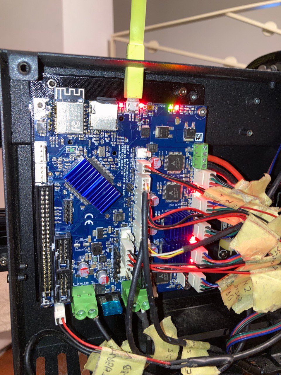
I post a picture of the LEDs that are on now.
-
@genioluiz7 flash it using M997 S1
-
@jay_s_uk as you can see the 'diag' light is on, between the SD card and USB.
So I follow the next instruction you send me previous in this conversation:
On Duet 2, in normal operation:- the DIAG LED will turn on as power is applied, then turn off as soon as the firmware starts loading, usually less than 0.5 second.
- In normal operation, it will turn back on if the probe type is set to M558 P1 in config.g. Removing the SD card and resetting should switch it off. Apart from this case, the DIAG LED should normally be off.
- Errors in config.g may cause the Duet to get stuck in a boot loop, which will cause the DIAG LED to be on permanently. Remove SD card and reset.
- If the reset button is stuck in (rare), or has been mounted so it is pushed in by an enclosure, the Duet will get stuck in a boot loop, which will cause the DIAG LED to be on permanently. Check there is clearance around the reset button, or use some tweezers to gently pull the button out.
- If the firmware has been erased the DIAG LED will be on permanently.
Diag LED still on
I tried also to flash it with BOSSA, with the erase pin but the LED doesn't turn off.
Now when I connect via USB the YAT software doesn't detect the COM10
-
Do you still have the heat sinks mounted? Perhaps they are making contact and shorting something.
Have you removed the board from the case and disconnected everything except for the USB connection?
Give the board a blast of compressed air to dislodge any debris that may be causing a short.
Does anything get hot to the touch shortly after being connected to usb power?
-
- Do you still have the heat sinks mounted? Perhaps they are making contact and shorting something.
No, they are correctly mounted.
Have you removed the board from the case and disconnected everything except for the USB connection?- Give the board a blast of compressed air to dislodge any debris that may be causing a short.
Ok
- Does anything get hot to the touch shortly after being connected to usb power?
No, nothing
As you can see below, I unplugged everything, and everything is clean and all the LEDs are on.

Now the COM10 is detected. So I tried the Fallback procedure #2 with BOSSA, but after clicked Write I clicked Verify and this warning message appeared.
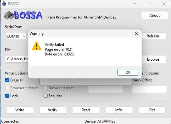
What could I do now?
-
@genioluiz7 did the heatsinks come with the board?
-
@jay_s_uk yes
-
@genioluiz7 then its a clone board and not covered by a duet warranty etc. Clone boards come with those blue heatsinks, duet boards do not.
If its none functioning then theres not much you can do -
@jay_s_uk Since I bought it from someone else, could it be that they were added later? I believe that is original.
I said yes becouse when I received the board they were already mounted. Ma non so di più.
-
@genioluiz7 i mean you could add them later.
The ultimate way to tell would be remove the heatsinks on the main MCU and see if theres any evidence of a sticker.
Having the heatsinks on the drivers and MCU do nothing anyway as the board takes the heat away -
@genioluiz7 ignore the DIAG LED. On Duet 2 it is shared with the Z probe command pin, so it doesn't mean anything, except that for certain startup errors it will flash an error code.
When you flashed the board using Bossa, did you remove the Erase jumper before pressing the Write button? If you don't remove it then the write will fail, leading to lots of verify errors.
Duet WiFi hardware designer and firmware engineer
Please do not ask me for Duet support via PM or email, use the forum
http://www.escher3d.com, https://miscsolutions.wordpress.com -
@dc42 Thanks for the suggestion on the LED Diag.
Yes, I followed the instructions about that. I can show what I did in particular:
Turned off Duet
Put Jumpering the erase jumper.
Turned on Duet for few sec.
Than turned off.
Removed the erase jumper.
Turned on Duet again.
Then pressed the Reset button.
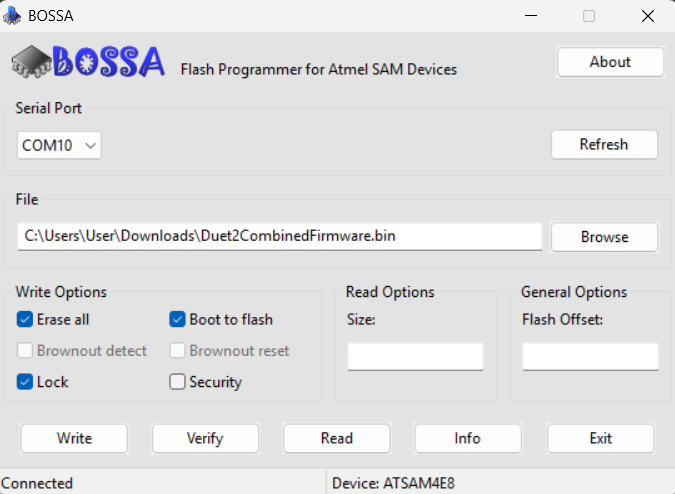
Opened Bossa and selected COM10 and checked boxes Erase all, Lock, and Boot to flash, then press Write. The write process worked
After I clicked Verify and at the end I got the warning message (Verify failed Page errors: 1021 Byte errors: 63923) and I stoped -
@genioluiz7 if the Erase jumper was definitely not in place when you ran Bossa, then sadly I think the flash memory of the main processor on the Duet as been damaged. The only other possibility I can think of is that the 3.3V rail is low, perhaps because something powered by it is drawing excessive current. If you have a multimeter, you could measure the voltage between the 3.3V and ground pins of one of the endstop connectors.