• Tags
  • Documentation
  • Order
  • Register
  • Login
Duet3D Logo Duet3D
  • Tags
  • Documentation
  • Order
  • Register
  • Login

Fly-SHT36 Max V3 RP2040 Based CAN-FD Toolboard

Scheduled Pinned Locked Moved
RepRapFirmware on other controllers
3
44
1.6k
Loading More Posts
  • Oldest to Newest
  • Newest to Oldest
  • Most Votes
Reply
  • Reply as topic
Log in to reply
This topic has been deleted. Only users with topic management privileges can see it.
  • undefined
    CrazyCreator @jay_s_uk
    last edited by 28 Mar 2025, 18:18

    @jay_s_uk
    So ... Now i have the first Question 😉

    ; TestFan - Zum testen des FAN Port's am Fly-SHT36 Max V3
    M950 F10 C"124.out13" Q500	; create fan 10 on pin gpio13 on Fly-SHT36 Max V3 Board and set its frequency
    M106 P10 C"TEST-Fan" H-1	; set fan 10 value. Thermostatic control is turned OFF
    

    I wrote this in my config.g, but without success.
    The FAN is connected to the GPIO13 FAN0
    Is a 24V Fan and the jumper is setting on the VCC

    http://www.crazycreatorcube.com

    undefined 1 Reply Last reply 28 Mar 2025, 18:20 Reply Quote 0
    • undefined
      jay_s_uk @CrazyCreator
      last edited by 28 Mar 2025, 18:20

      @CrazyCreator thats incorrect naming
      the correct names to use can be found in this table here
      https://teamgloomy.github.io/fly_sht36_max_v3_pins.html#fly-sht36-max-v3-other-pins-in-firmware

      Owns various duet boards and is the main wiki maintainer for the Teamgloomy LPC/STM32 port of RRF. Assume I'm running whatever the latest beta/stable build is

      undefined 3 Replies Last reply 28 Mar 2025, 18:20 Reply Quote 0
      • undefined
        CrazyCreator @jay_s_uk
        last edited by 28 Mar 2025, 18:20

        @jay_s_uk Why didn't I see the button? Thank you.

        http://www.crazycreatorcube.com

        1 Reply Last reply Reply Quote 0
        • undefined
          CrazyCreator @jay_s_uk
          last edited by CrazyCreator 28 Mar 2025, 19:21

          @jay_s_uk
          So the entry for my test fan now looks like this:

          M950 F10 C"124.out1" Q500 	
          M106 P10 S255				
          

          It also appears in the frontend, but when I increase it with the slider, nothing happens.
          but on SHT a blue LED lights up synchronously to control the slider
          I think I need to test my cables and plugs

          http://www.crazycreatorcube.com

          undefined 1 Reply Last reply 28 Mar 2025, 20:09 Reply Quote 0
          • undefined
            CrazyCreator @jay_s_uk
            last edited by 28 Mar 2025, 20:08

            @jay_s_uk
            I've now checked all the cables and crimped a new one.

            But the fan remains silent.

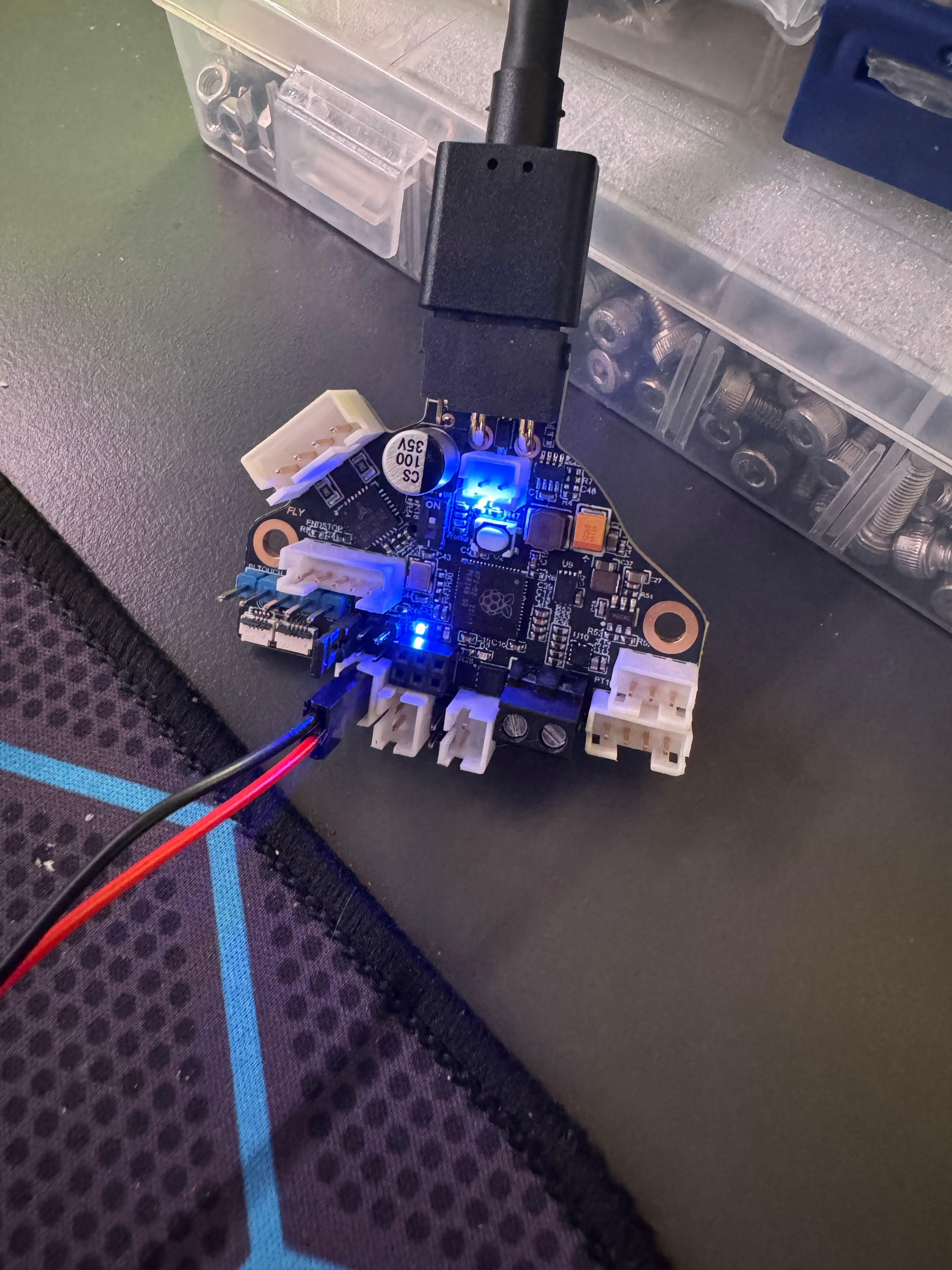
            I've attached a picture with the perhaps silly question: Did I set the jumper for 24V correctly?
            There's 24V at the connector above, I measured it, and the fan is a 24V fan.

            IMG_0706.jpg

            http://www.crazycreatorcube.com

            undefined 1 Reply Last reply 28 Mar 2025, 20:10 Reply Quote 0
            • undefined
              jay_s_uk @CrazyCreator
              last edited by 28 Mar 2025, 20:09

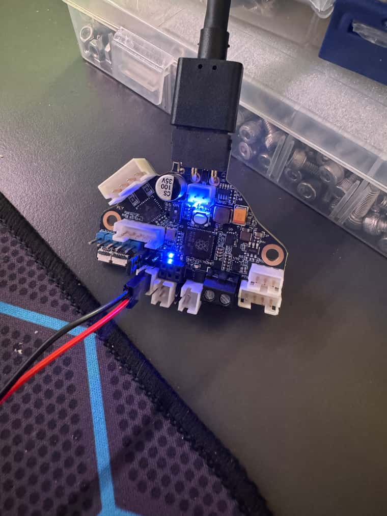
              @CrazyCreator did you install the fan mosfet?

              Owns various duet boards and is the main wiki maintainer for the Teamgloomy LPC/STM32 port of RRF. Assume I'm running whatever the latest beta/stable build is

              1 Reply Last reply Reply Quote 0
              • undefined
                jay_s_uk @CrazyCreator
                last edited by 28 Mar 2025, 20:10

                @CrazyCreator looks like you didn't
                https://teamgloomy.github.io/fly_sht36_max_v3_general.html#fan-mosfets

                Owns various duet boards and is the main wiki maintainer for the Teamgloomy LPC/STM32 port of RRF. Assume I'm running whatever the latest beta/stable build is

                undefined 1 Reply Last reply 28 Mar 2025, 20:17 Reply Quote 0
                • undefined
                  CrazyCreator @jay_s_uk
                  last edited by 28 Mar 2025, 20:17

                  @jay_s_uk
                  Oh dear... How could I have forgotten that? I put the MOSFET in a small bowl so I wouldn't forget it!!!

                  Now the fan works too 🙂

                  http://www.crazycreatorcube.com

                  1 Reply Last reply Reply Quote 1
                  • undefined
                    CrazyCreator
                    last edited by 30 Mar 2025, 16:36

                    So... Let's move on 🙂

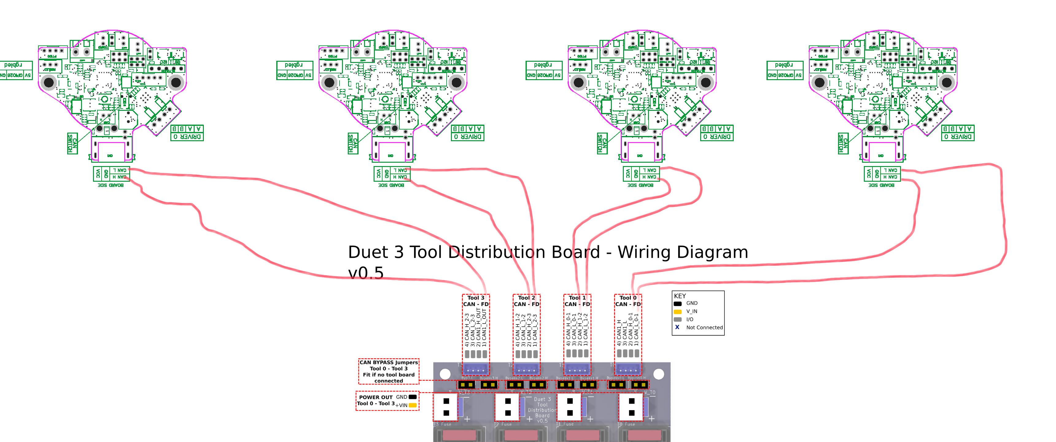
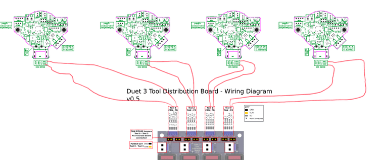
                    Since the SHT36 is working so well, I got a toolboard yesterday and now want to connect 4 SHT36s to it.

                    Is the CAN wiring in my ugly drawing correct?

                    ToolBoardTo4xSHT.png

                    http://www.crazycreatorcube.com

                    undefined 1 Reply Last reply 30 Mar 2025, 16:45 Reply Quote 0
                    • undefined
                      jay_s_uk @CrazyCreator
                      last edited by 30 Mar 2025, 16:45

                      @CrazyCreator that looks fine.
                      You'll need the bypass jumpers in place as these are being treated as stubs.
                      https://docs.duet3d.com/en/User_manual/Machine_configuration/CAN_connection#stubs

                      https://docs.duet3d.com/en/Duet3D_hardware/Duet_3_family/Duet_3_Tool_Distribution_Board#h-2-wire-connection

                      Owns various duet boards and is the main wiki maintainer for the Teamgloomy LPC/STM32 port of RRF. Assume I'm running whatever the latest beta/stable build is

                      undefined 1 Reply Last reply 30 Mar 2025, 16:49 Reply Quote 0
                      • undefined
                        CrazyCreator @jay_s_uk
                        last edited by 30 Mar 2025, 16:49

                        @jay_s_uk Currently, all 8 jumpers are plugged in. I think that's correct, right?

                        http://www.crazycreatorcube.com

                        undefined 1 Reply Last reply 30 Mar 2025, 18:26 Reply Quote 0
                        • undefined
                          jay_s_uk @CrazyCreator
                          last edited by 30 Mar 2025, 18:26

                          @CrazyCreator yes, that's right

                          Owns various duet boards and is the main wiki maintainer for the Teamgloomy LPC/STM32 port of RRF. Assume I'm running whatever the latest beta/stable build is

                          1 Reply Last reply Reply Quote 1
                          • undefined
                            CrazyCreator
                            last edited by CrazyCreator 19 Apr 2025, 01:18

                            Today I finally got back to my printer 🙂 and have a little bit of work ahead of me for tomorrow.

                            I would like to connect a GL-8FN1 sensor as an X-Endstop to the SHT36.
                            Unfortunately, I've only found these two options:
                            Bildschirmfoto 2025-04-19 um 03.17.53.png
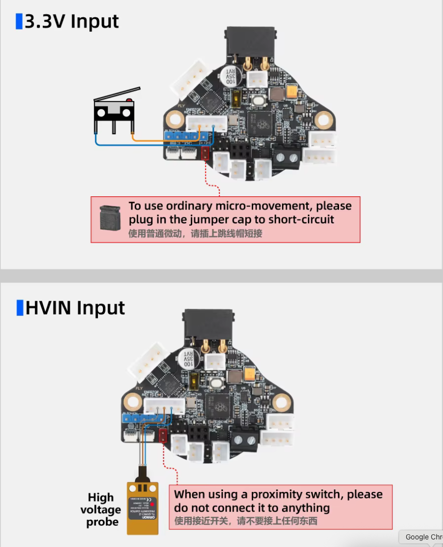
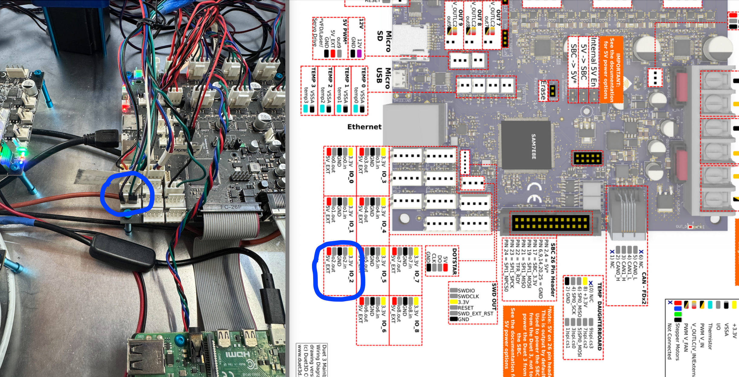
                            And now I'm not sure if the "HVIN" input corresponds to my sensor.

                            I'm already using the same sensor as a Y-Endstop. It's connected to the MB6HC, of ​​course:

                            M574 Y1 S1 P"!io2.in" ; configure switch-type (e.g., microswitch) endstop for low end on Y via pin io2.in
                            

                            Unfortunately, I'm currently a bit unsure about which pins I should use on the SHT36.

                            http://www.crazycreatorcube.com

                            undefined 1 Reply Last reply 19 Apr 2025, 05:28 Reply Quote 0
                            • undefined
                              jay_s_uk @CrazyCreator
                              last edited by 19 Apr 2025, 05:28

                              @CrazyCreator looks like it runs on 12-24v so same has the HVIN

                              Owns various duet boards and is the main wiki maintainer for the Teamgloomy LPC/STM32 port of RRF. Assume I'm running whatever the latest beta/stable build is

                              undefined 1 Reply Last reply 19 Apr 2025, 10:20 Reply Quote 0
                              • undefined
                                CrazyCreator @jay_s_uk
                                last edited by CrazyCreator 19 Apr 2025, 10:20

                                @jay_s_uk
                                It's this sensor: https://s.click.aliexpress.com/e/_oo1zqJ5

                                And it's connected like this:
                                Bildschirmfoto 2025-04-19 um 12.17.20.png

                                http://www.crazycreatorcube.com

                                undefined 1 Reply Last reply 19 Apr 2025, 11:34 Reply Quote 0
                                • undefined
                                  jay_s_uk @CrazyCreator
                                  last edited by 19 Apr 2025, 11:34

                                  @CrazyCreator then just a normal end stop then

                                  Owns various duet boards and is the main wiki maintainer for the Teamgloomy LPC/STM32 port of RRF. Assume I'm running whatever the latest beta/stable build is

                                  undefined 1 Reply Last reply 21 Apr 2025, 15:55 Reply Quote 0
                                  • undefined
                                    CrazyCreator @jay_s_uk
                                    last edited by CrazyCreator 21 Apr 2025, 15:55

                                    @jay_s_uk Hello ... Ready now 😃

                                    MicroProbe and Proximity Sensor connected and working (in Testconfig).

                                    Only if you interested, there the part from config.g

                                    ; Endstops
                                    M574 X1 S1 P"!124.io1.in"                                                               ; configure switch-type (e.g. microswitch) endstop for low end on X via pin 124.io1.in on Fly-SHT36 Max V3
                                    M574 Y1 S1 P"!io2.in"                                                                   ; configure switch-type (e.g. microswitch) endstop for low end on Y via pin io2.in on MB6HC
                                    M574 Z1 S2                                                                              ; configure Z-probe endstop for low end on Z on Fly-SHT36 Max V3
                                    
                                    ; Z-Probes 
                                    ; Configuration for Z-Probe - BTT BiQu MicroProbe V1
                                    M558 P9 H6 F250:30 T8000 C"^124.io0.in"                                                 ; set Z probe type to microprobe and the dive height + speeds
                                    M950 P0 C"124.io0.out"                                                                  ; Setup 124.io0.out as on/off port on Fly-SHT36 Max V3
                                    G31 P500 X0 Y0 Z0.7                                                                     ; set Z probe trigger value, offset and trigger height
                                    
                                    ; Configuration for Scanning Probe from SHT36
                                    M558 K1 P11 C"124.i2c.ldc1612" H5 F120 T6000                                            ; configure scanning probe via slot #1
                                    G31 P500 X0 Y0 Z0.7                                                                     ; set Z probe trigger value, offset and trigger height
                                    
                                    ; Define Mesh Grid and Probing Points distance
                                    M557 X30:360 Y15:330 P5                                                                 ; define mesh grid
                                    

                                    Bildschirmfoto 2025-04-21 um 17.56.01.png 
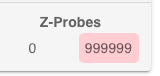
I think this is normal, because the Scanning Probe is not connected?

                                    http://www.crazycreatorcube.com

                                    undefined 1 Reply Last reply 21 Apr 2025, 17:23 Reply Quote 0
                                    • undefined
                                      jay_s_uk @CrazyCreator
                                      last edited by 21 Apr 2025, 17:23

                                      @CrazyCreator yes, if it's not connected it'll read like that. It'll also read like that if it's not calibrated

                                      Owns various duet boards and is the main wiki maintainer for the Teamgloomy LPC/STM32 port of RRF. Assume I'm running whatever the latest beta/stable build is

                                      undefined 2 Replies Last reply 21 Apr 2025, 17:33 Reply Quote 0
                                      • undefined
                                        CrazyCreator @jay_s_uk
                                        last edited by 21 Apr 2025, 17:33

                                        @jay_s_uk
                                        That will be the next project. Calibrating the scanner... Yeaaaaah 😞

                                        http://www.crazycreatorcube.com

                                        1 Reply Last reply Reply Quote 0
                                        • undefined
                                          CrazyCreator @jay_s_uk
                                          last edited by CrazyCreator 22 Apr 2025, 21:53

                                          @jay_s_uk
                                          Can you help me again?

                                          When I send the MicroProbe to probe the bed, it moves to the planned point and the pin pops out briefly but then goes back in immediately
                                          and the bed stops.
                                          The DWC Show: Z-Probe 0
                                          Bildschirmfoto 2025-04-22 um 23.41.24.png
                                          Then the error message appears:
                                          Bildschirmfoto 2025-04-22 um 23.41.38.png
                                          The config.g for this:

                                          ; Endstops
                                          M574 X1 S1 P"!124.io1.in"                                                               ; configure switch-type (e.g. microswitch) endstop for low end on X via pin 124.io1.in on Fly-SHT36 Max V3
                                          M574 Y1 S1 P"!io2.in"                                                                   ; configure switch-type (e.g. microswitch) endstop for low end on Y via pin io2.in on MB6HC
                                          M574 Z1 S2                                                                              ; configure Z-probe endstop for low end on Z on Fly-SHT36 Max V3
                                          
                                          ; Z-Probes 
                                          ; Configuration for Z-Probe - BTT BiQu MicroProbe V2
                                          M558 P9 H6 F250:30 T8000 C"^124.io0.in"                                                ; set Z probe type to microprobe and the dive height + speeds
                                          M950 P0 C"124.io0.out"                                                                  ; Setup io0.out as on/off port on Fly-SHT36 Max V3
                                          G31 P500 X30.01 Y48.6 Z0.7                                                              ; set Z probe trigger value, offset and trigger height
                                          
                                          ; Configuration for Scanning Probe from SHT36
                                          ;M558 K1 P11 C"124.i2c.ldc1612" H5 F120 T6000                                           ; configure scanning probe via slot #1
                                          ;G31 P500 X0 Y0 Z0.7                                                                    ; set Z probe trigger value, offset and trigger height
                                          
                                          ; Define Mesh Grid and Probing Points distance
                                          M557 X30:300 Y15:250 P5                                                                 ; define mesh grid


                                          When i try the other way in config.g with !

                                          ; Endstops
                                          M574 X1 S1 P"!124.io1.in"                                                               ; configure switch-type (e.g. microswitch) endstop for low end on X via pin 124.io1.in on Fly-SHT36 Max V3
                                          M574 Y1 S1 P"!io2.in"                                                                   ; configure switch-type (e.g. microswitch) endstop for low end on Y via pin io2.in on MB6HC
                                          M574 Z1 S2                                                                              ; configure Z-probe endstop for low end on Z on Fly-SHT36 Max V3
                                          
                                          ; Z-Probes 
                                          ; Configuration for Z-Probe - BTT BiQu MicroProbe V2
                                          M558 P9 H6 F250:30 T8000 C"^!124.io0.in"                                                ; set Z probe type to microprobe and the dive height + speeds
                                          M950 P0 C"124.io0.out"                                                                  ; Setup io0.out as on/off port on Fly-SHT36 Max V3
                                          G31 P500 X30.01 Y48.6 Z0.7                                                              ; set Z probe trigger value, offset and trigger height
                                          
                                          ; Configuration for Scanning Probe from SHT36
                                          ;M558 K1 P11 C"124.i2c.ldc1612" H5 F120 T6000                                           ; configure scanning probe via slot #1
                                          ;G31 P500 X0 Y0 Z0.7                                                                    ; set Z probe trigger value, offset and trigger height
                                          
                                          ; Define Mesh Grid and Probing Points distance
                                          M557 X30:300 Y15:250 P5                                                                 ; define mesh grid
                                          

                                          If I connect it like this, the MicroProbe works. The pin pops out and is triggered by the bed, and the bed stops.

                                          BUT then I see a red 1000 on the display.
                                          Bildschirmfoto 2025-04-22 um 23.45.42.png

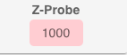
                                          But the homing works perfectly fine, even though it says 1000 in red. That's kind of surprising, because that's not how it's supposed to be, is it?

                                          Maybe you can take a look at my configuration?

                                          Attached are config.g and the homing files:
                                          config.g
                                          homeall.g
                                          homex.g
                                          homey.g
                                          homez.g

                                          Maybe

                                          http://www.crazycreatorcube.com

                                          undefined 1 Reply Last reply 23 Apr 2025, 05:37 Reply Quote 0
                                          • First post
                                            Last post
                                          Unless otherwise noted, all forum content is licensed under CC-BY-SA