Sovol SV08 Multiple Motion System Upgrade.
-
@dwuk3d Where did you find the CAD files for the INDX? Annoyingly, the Discord link on https://www.bondtech.se/indx-by-bondtech/ is not valid.
Ian
Bed-slinger - Mini5+ WiFi/1LC | RRP Fisher v1 - D2 WiFi | Polargraph - D2 WiFi | TronXY X5S - 6HC/Roto | CNC router - 6HC | Tractus3D T1250 - D2 Eth
-
@droftarts I have posted about the problem on the Discord and they say they will update the link with a permanent one - so hopefully it will be fixed soon.
Re the CAD - it's not to scale - I just knocked up a rough presentation of the components from a few screenshots from the video an the 3D Musketeers Podcast - so that I could play with different configurations.
-
@dwuk3d Bondtech INDX Projected costs now out - $35 per tool head. Really happy with that.
$250 for the toolhead/extruder - a bit pricey - but worth it I think for the reduced complexity the solution brings.Availability Nov25 - which is quite a while off unfortunately.
Tool change time 12 secs, with heat up only 4 secs.
Overall looks very promising.
I don't think I could justify adding 4 toolheads at that price to my system - but two I think would work quite well - one on each gantry - with the IDEX extruders on the gantries being single colour, or maybe with an MMU/Box Turtle type add-on (which wouldn't have to wait until November).
-
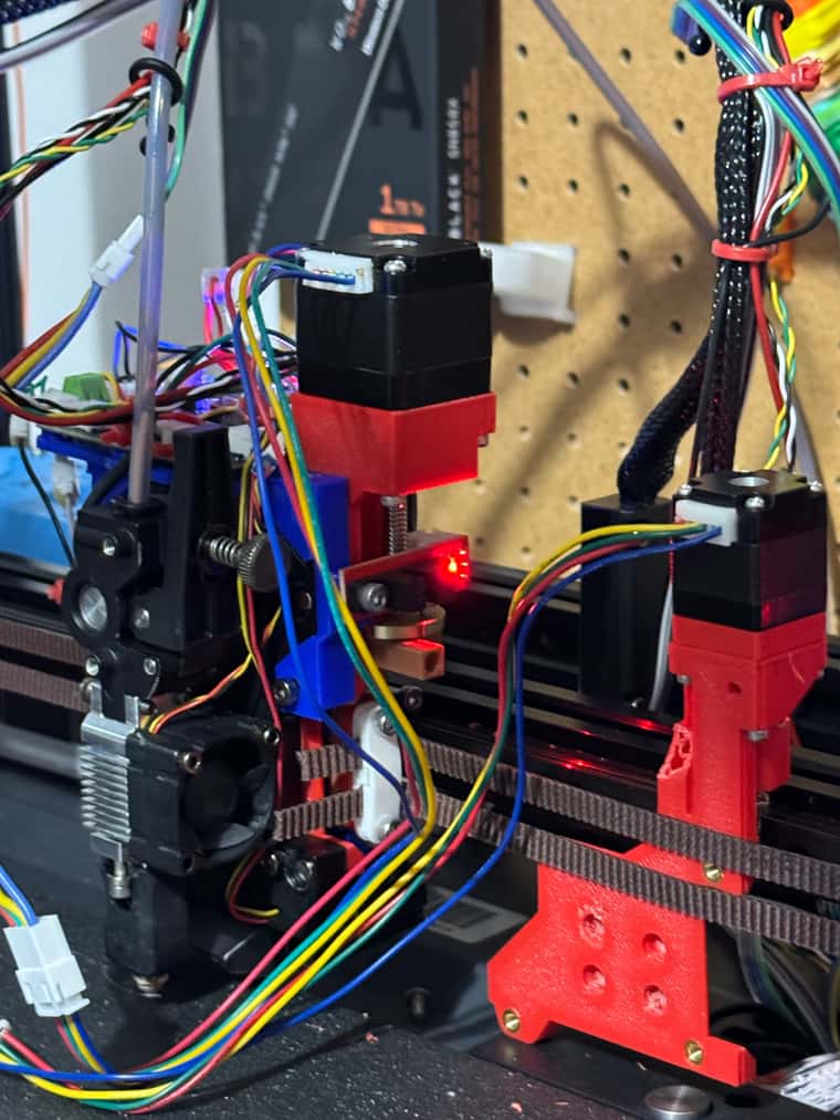
Might have solved the problem with my Nema8's - which seemed to work before but then stopped working.
I first thought it might be my new improved design and secondly maybe the firmware.
With the help of Physics Teacher Anthony - who reminded me that I need to lubricate the bolt - that helped a fair bit and the lifting improved - but the motor still kept stalling.
The biggest issue though was an oversight on my part re motor speed. I was just using the Dashboard controls - and I'm not sure how to control the speed.
But when I do a G1 H2 A1 F100 for example it seems to works ok - so I think I was just running the motor too fast from the dashboard in my initial tests.
If I had just connected up the end stop, and ran the proper homea.g with lower feed rates- It probably would have worked ok.
Will still investigate over engineering the lift motors a bit - but a good step forward.
-
@dwuk3d said in Sovol SV08 Multiple Motion System Upgrade.:
The biggest issue though was an oversight on my part re motor speed. I was just using the Dashboard controls - and I'm not sure how to control the speed.
You can change the feedrate in Settings > Machine-specific > Feedrate for move buttons (mm/min). However, it applies to all axis buttons, except extruder axes.
Ian
Bed-slinger - Mini5+ WiFi/1LC | RRP Fisher v1 - D2 WiFi | Polargraph - D2 WiFi | TronXY X5S - 6HC/Roto | CNC router - 6HC | Tractus3D T1250 - D2 Eth
-
@droftarts Thanks will try that.
I guess I should set the maximum feedrate for the motors in the stepper configs too - however the problem with that is gravity - i.e. They can go quite a lot faster downwards than up - and for Z hopping I should use the fully available speed in both directions.
-
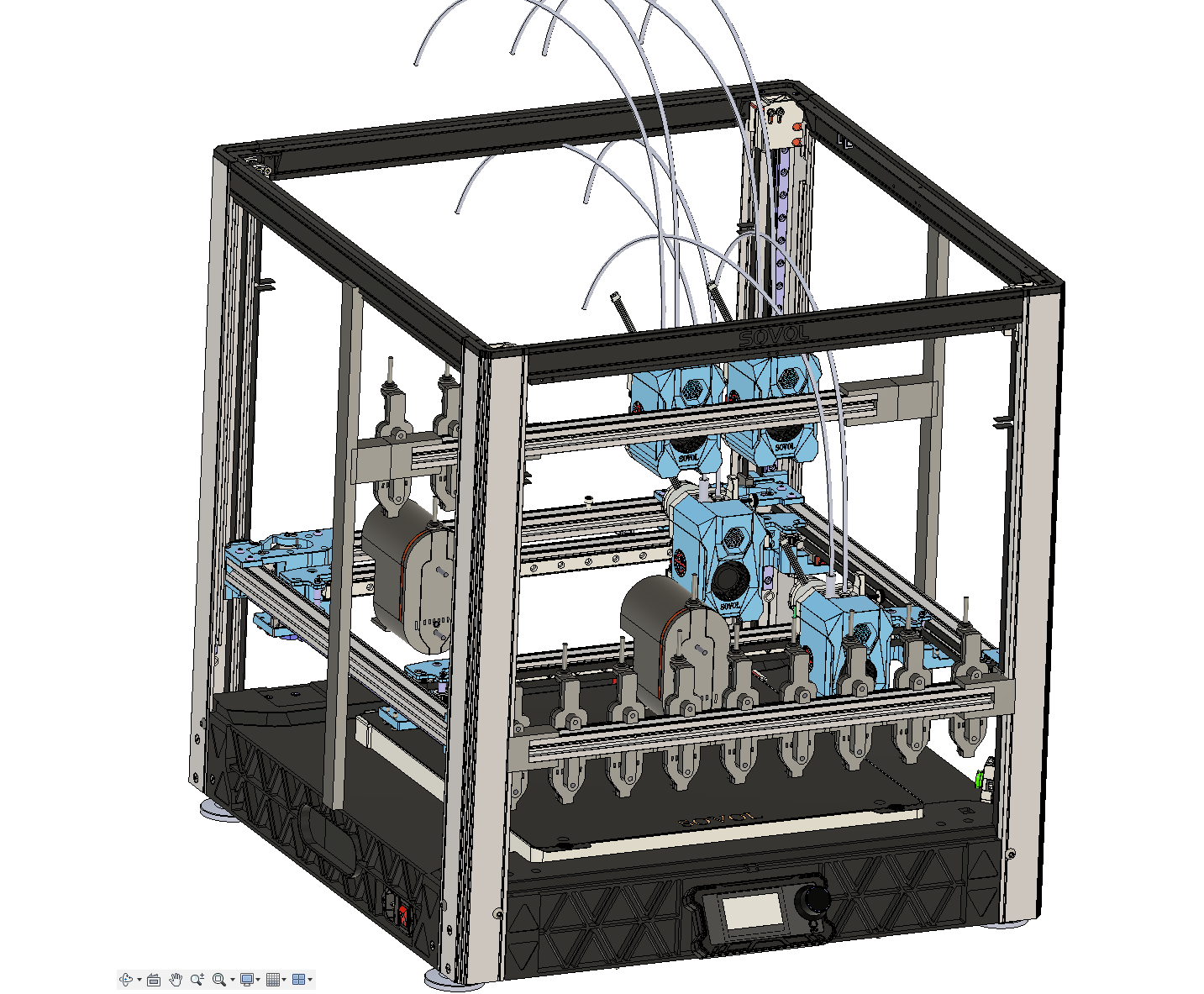
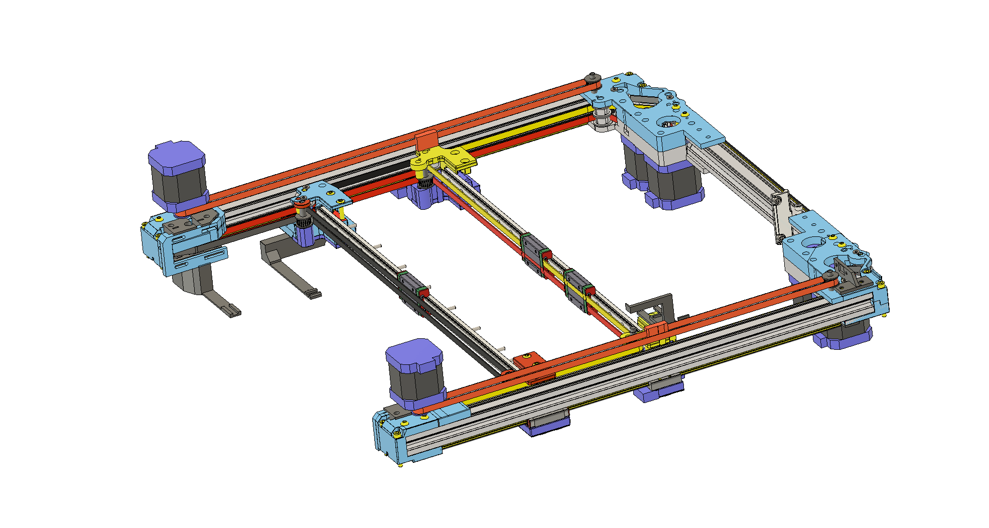
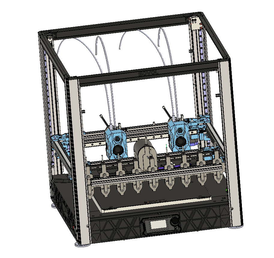
SV08 Double Gantry INDX option - with middle tool rack having independent Z
Tools can be moved between front and rear gantry.
Parallel Printing and Parallel tool changes
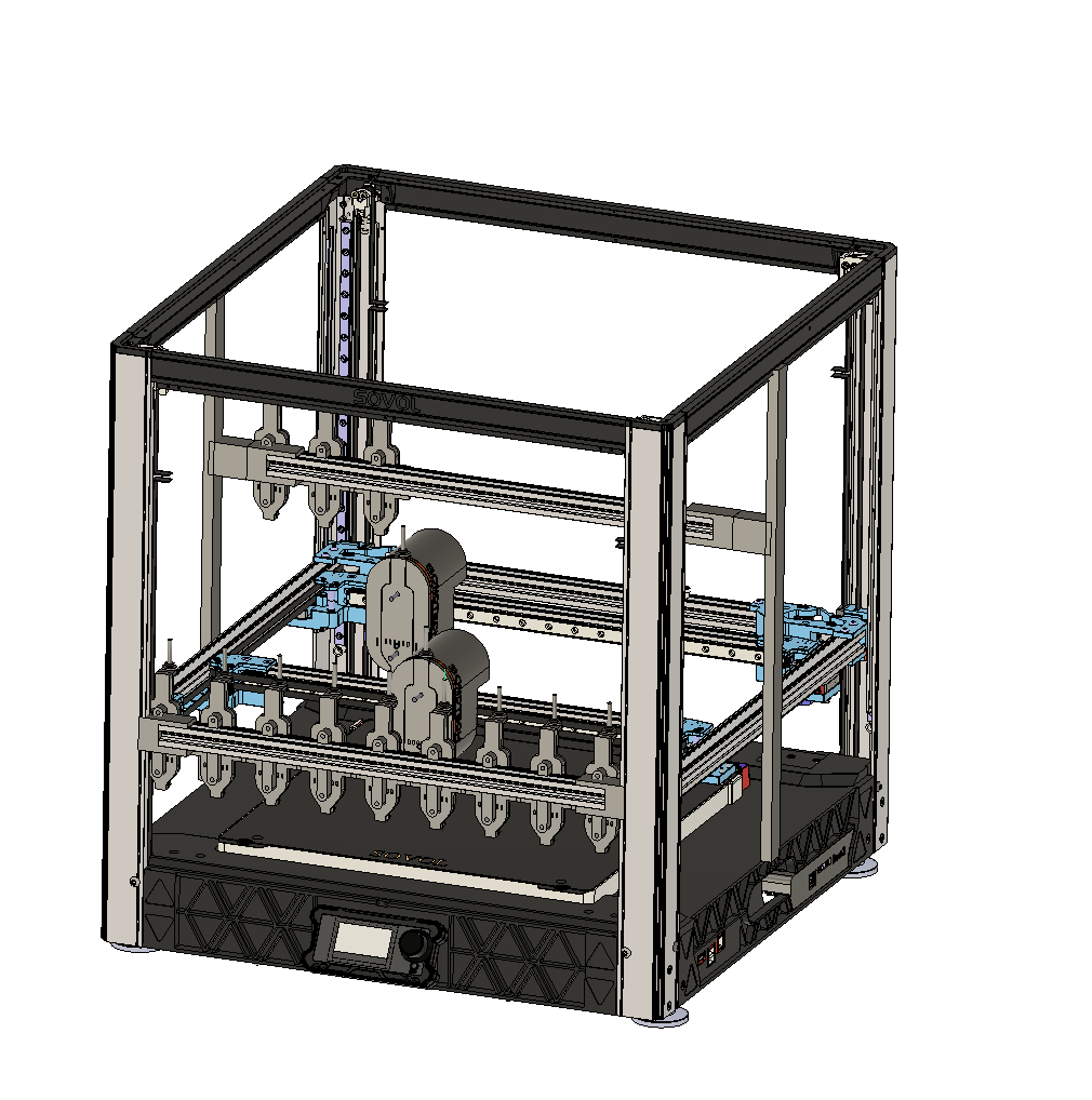
A bit messy - but probably what I might end up with -
INDX on 2 heads on both gantries - with IDEX too - using existing SOVOL heads, with option to offload both IDEX heads when not needed.
So this is making me think I will probably still do a tool changer upgrade on my printer if I complete the 4 head stage before INDX becomes available.
Some estimates of tool change/colour change times
INDX tool change is about 17 seconds in total including reheat and priming.
XL based on PrusaSlicer about 14 seconds (3 secs quicker).
Doing the same thing with Bambu Studio and an H2D - Intra Nozzle total change times seem to be estimated at 11.7 seconds (about 5.3 secs quicker). IDEX times likely to be similar
If you move all swaps to the same Nozzle then Bambu Studio estimates 76secs for a normal Multiplexing filament change.
Doing the same thing for an X1C comes out as 95 seconds per change -
An MK4 with MMU3 using the same method is estimating at 67 seconds per change.
Dual Gantry parallel INDX or Stealtchanger tool changes could be as quick as sub-second - and faster than Ratrig toolshift..
Parallel printing could then reduce single colour printing by appx 40% on dual gantry for some larger models, and by over 70% for symmetrical models on quad head printer.
-
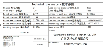
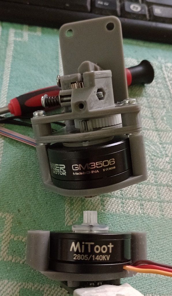
Don't really understand what is happening with my NEMA8 motor.
It started working pretty well with the slower speeds, and I created a sort of test bed - and it lifted 500g quite happily.
Then it stopped working - it might be electronic, the motor, or my mechanical design - I might be over constraining the bolt

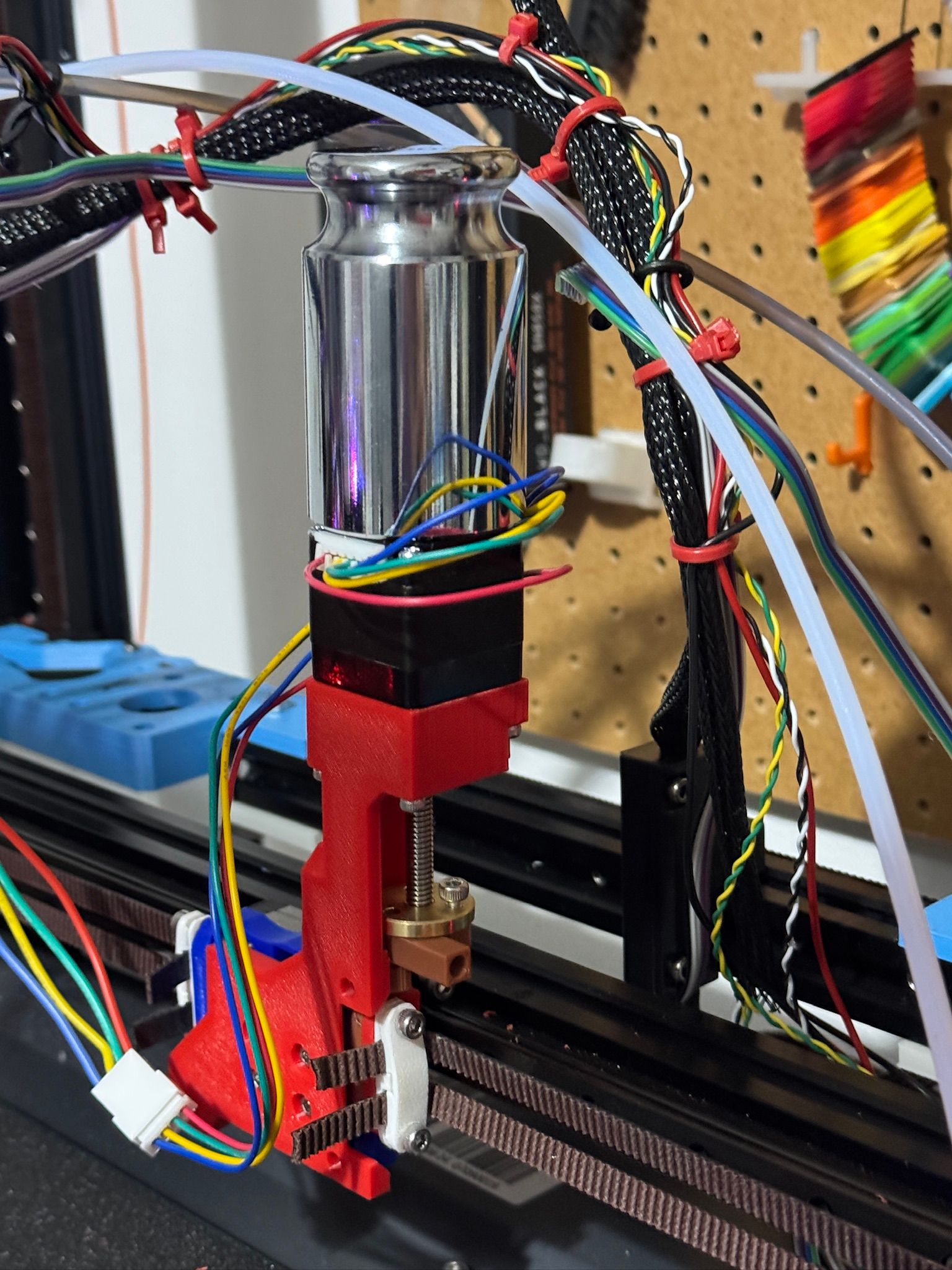
Lead Screw Nema11 now arrived - the lead screw is a bit long - 50mm - but will try that - with the coupler for the lead screw not too constrained if I get any trouble.
This motor is rated at 1.0A - will be interesting to see how more powerful it is.
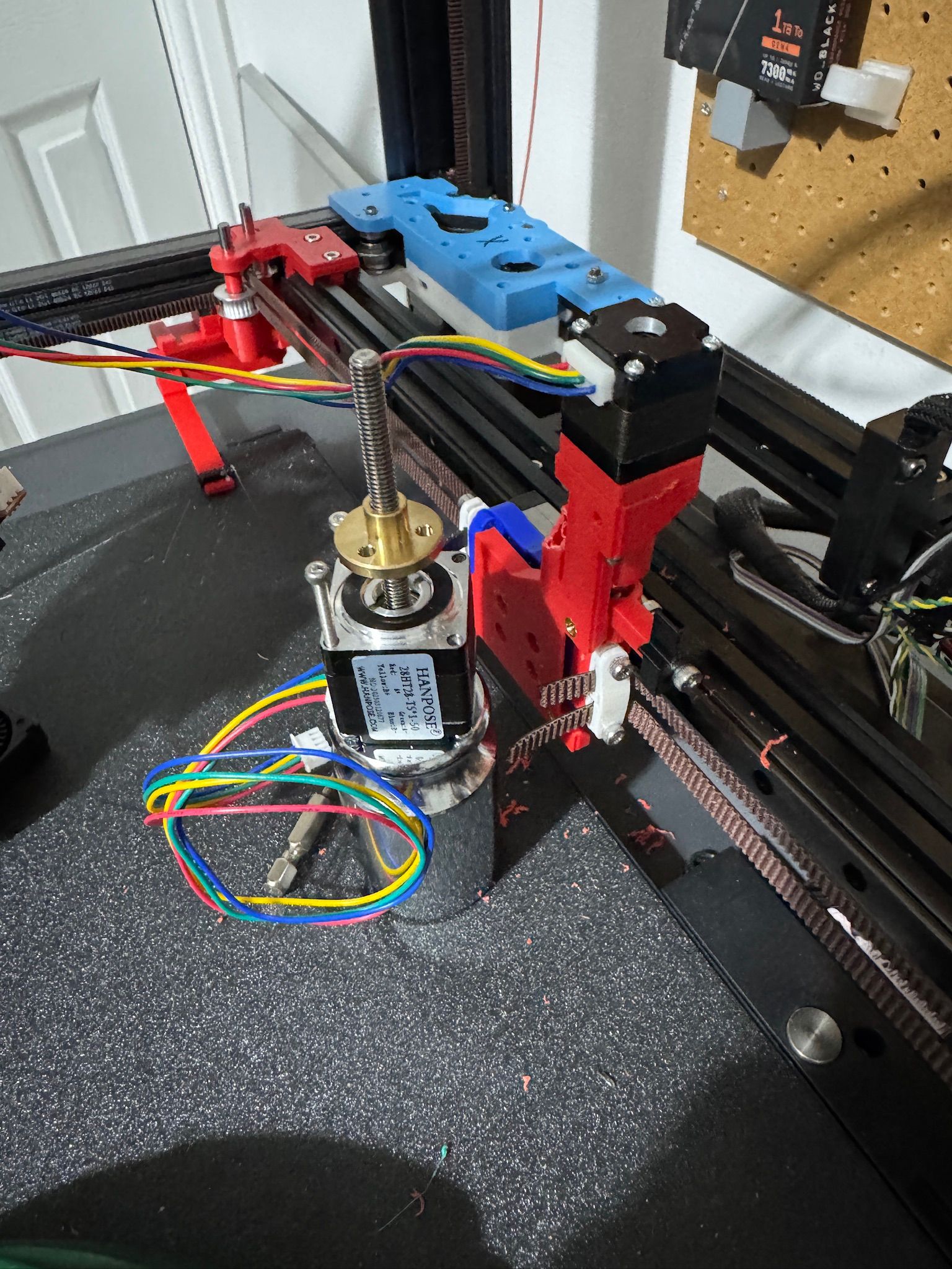
Nema 11 installed - sticks up more than it really needs to - might chop off the lead screw, or try and source one with shorter screw - but managing to lift 500g and the extruder so far
-
Simplified Dual IDEX belt routing.
Decided it will be easier to put one 'Ratrig Hybrid' Y Axis motor above (for rear gantry) and below (for front gantry).
It will mean that the bed needs to be raised up a bit - due to the height of the bottom motor - but this will be needed eventually anyway when I move
to an occasionally moving bed.Will have to redesign the extruder carriage belt couplings so that there is room one of the belts to fit through.
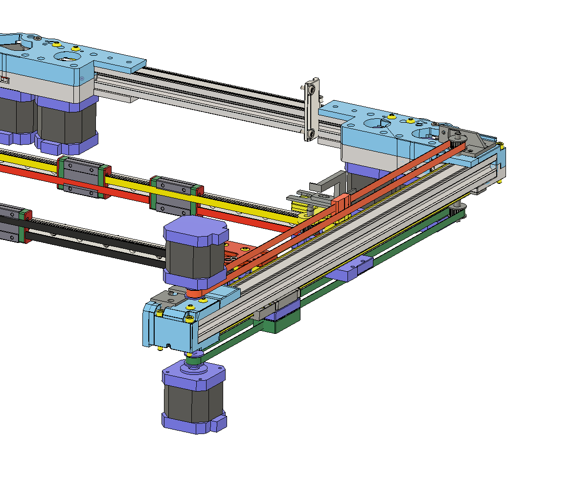
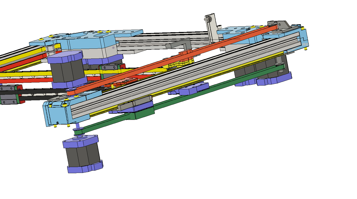
I think this should work well for the front gantry in particular as the belt fix point will be very near the Y axis rail carriage.
For the rear gantry they are further away - as the fix point is at the top - so there might be a slight pendulum effect.
Setup will be mirrored on the other side - could I suppose swap the top and bottom couplings - but I guess it will be better to keep both sides of each gantry the same.
-
@dwuk3d said in Sovol SV08 Multiple Motion System Upgrade.:
Don't really understand what is happening with my NEMA8 motor.
Their internal magnets might have degraded due to overheating? I noticed the same on some NEMA14 pancakes I used to use for extruders. They survived only when I reduced their rated current by 50%.
I replaced them with brushless gimbal motors and a selfmade simpleFOC-interface and the problem was gone.Torque/weight ratio improved a lot, too.
-
@o_lampe Thanks - looks interesting - especially the gearing you have added.
I would like to investigate adding some nylon or metal gears if I can source some suitable ones.
I haven't really investigated driving normal motors from Duet - but it would be useful to be able to try something like your motors if I can control them ok with GCODE.
I switched away from servo's partly as they didn't play well with parallel gcode processing.
I'm wondering whether the type of Servo Motors that BambuLab have started using in the H2D extruder and AMS2 might be of use.
I guess the ideal solution would involve some sort of close loop feedback and temperature monitoring.
Think I will at least put some speed and reliability testing in my Macros - I think I should be able to home the ZHopper AXIS, do a few up and down movements and check the home point hasn't drifted due to missed steps.
Could also I guess use the same method to find the maximum move speeds up and down, plus also use the same method on my U & V axis with their optical end stops.
So far in my first steps my Nema11 seems to be able to handle F1000 moves up - which look pretty fast. -
Nema11 seems to be able to handle F1900 on a 1mm pitch lead screw - which is faster than I expected.
Started to get a bit warm at end of test - so probably shouldn't push it that hard - will probably limit this ZHopper to F500 or F1000
Test sequence was:
I homed A.
Then lifted it 0.2 slowly (F100)
Then lifted it at the test rate 1mm
Then lowered it slowly (F100) back to the end stop using G1 H4 - to check how far it had drifted.
Then G92 A0 - to reset end stop - and repeat.
5 times for each federate31/03/2025, 09:34:54 rate 2000 max pos 0.033 average 0.0107500 total 0.054
31/03/2025, 09:34:49 rate 1900 max pos 0.015 average 0.0075000 total 0.038
31/03/2025, 09:34:44 rate 1800 max pos 0.015 average 0.0068750 total 0.034
31/03/2025, 09:34:38 rate 1700 max pos 0.014 average 0.0044375 total 0.022
31/03/2025, 09:34:33 rate 1600 max pos 0.010 average 0.0045625 total 0.023
31/03/2025, 09:34:28 rate 1500 max pos 0.014 average 0.0034375 total 0.017
31/03/2025, 09:34:22 rate 1400 max pos 0.004 average 0.0018125 total 0.009
31/03/2025, 09:34:17 rate 1300 max pos 0.006 average 0.0039375 total 0.020
31/03/2025, 09:34:12 rate 1200 max pos 0.008 average 0.0050000 total 0.025
31/03/2025, 09:34:06 rate 1100 max pos 0.008 average 0.0030000 total 0.015
31/03/2025, 09:34:01 rate 1000 max pos 0.004 average 0.0023125 total 0.012
31/03/2025, 09:33:55 rate 900 max pos 0.002 average 0.0006250 total 0.003
31/03/2025, 09:33:50 rate 800 max pos 0.003 average 0.0023750 total 0.012
31/03/2025, 09:33:44 rate 700 max pos 0.005 average 0.0023125 total 0.012
31/03/2025, 09:33:39 rate 600 max pos 0.010 average 0.0057500 total 0.029
31/03/2025, 09:33:33 rate 500 max pos 0.002 average 0.0010000 total 0.005
31/03/2025, 09:33:27 rate 400 max pos 0.003 average 0.0013750 total 0.007
31/03/2025, 09:33:22 rate 300 max pos 0.007 average 0.0036250 total 0.018
31/03/2025, 09:33:15 M98 P"0:/macros/Speed TestA.g"
rate 200 max pos 0.014 average 0.0061875 total 0.031Test Macro
;Speed TestA.g

M98 P"homeA.g"
M400
G91
var maxV = 0
var totalV = 0
var count = 0
var rate = 200
while var.rate <= 2000
    while iterations < 5
        G1 A0.2 F100
        M400
        G1 A1 F{var.rate}
        G1 H4 A-2 F100
        M400
        var pos = abs(move.axes[5].machinePosition)
        if var.pos > var.maxV
            set var.maxV = var.pos
        set var.totalV = var.totalV + var.pos
        set var.count = var.count + 1

        G92 A0
        if var.pos > 0.1
            break

    echo "rate",{var.rate},"max pos",{var.maxV},"average",{var.totalV}/{var.count},"total",{var.totalV}
    if var.maxV > 0.1
        break
    set var.rate = var.rate + 100
    set var.maxV = 0
    set var.totalV = 0
    set var.count = 0
Config
; Smart Drivers M569 P0.0 S1 D2 ; driver 0.0 goes forwards (Z axis) M569 P0.1 S1 D2 ; driver 0.1 goes forwards (Z axis) M569 P0.2 S0 D2 ; driver 0.2 goes backwards (Z axis) M569 P0.3 S1 D2 ; driver 0.3 goes forwards (X axis) M569 P0.4 S0 D2 ; driver 0.4 goes backwards (Y axis) M569 P1.3 S1 D2 ; driver 0.5 goes backwards (Z axis) - changed to 1.3 forwards ;M569 P1.0 S0 D3 V2000 ; driver 1.0 goes backwards (U axis) ;M569 P1.1 S0 D3 V2000 ; driver 1.1 goes backwards (V axis) M569 P1.0 S0 D2; driver 1.0 goes backwards (U axis) M569 P1.1 S0 D2 ; driver 1.1 goes backwards (V axis) M569 P1.4 S0 D2 ; Z-hopper 2 M569 P0.5 S1 D2 ; Z-hopper 1 M569 P121.0 S0 D2 ; driver 121.0 goes backwards (extruder 0) M569 P122.0 S0 D2 ; driver 122.0 goes backwards (extruder 1) ; Motor Idle Current Reduction M906 I30 ; set motor current idle factor M84 S30 ; set motor current idle timeout ; Axes M584 X0.3 Y0.4 Z0.1:0.2:0.0:1.3 U1.0 V1.1 A1.4 B0.5; set axis mapping M350 X16 Y16 Z16 U16 V16 A16 B16 I1 ; configure microstepping with interpolation M906 X800 Y800 Z800 U800 V800 A750 B150 ; set axis driver currents ; A - 1.8 degree, 0.7mm pitch - 200*16/0.7 = 4571 ; A - 1.8 degree, 1mm pitch - 200*16 = 3200 M92 X80 Y80 Z533.33 U80 V80 A3200 B629 ; configure steps per mm if exists(global.vMin) == false global vMin = 120 global vMax = 340 global yMin = -5 global yMax = 210 M208 X-5:310 Y-5:210 Z0:300 U27:350 V120:340 A0:3 B0:3 ; set minimum and maximum axis limits M566 X540 Y540 Z12 U540 V540 A300 B300 ; set maximum instantaneous speed changes (mm/min) M203 X10000 Y10000 Z720 U10000 V10000 A2000 B200 ; set maximum speeds (mm/min) M201 X10000 Y10000 Z500 U10000 V10000 A2000 B20 ; set accelerations (mm/s^2) -
@dwuk3d said in Sovol SV08 Multiple Motion System Upgrade.:
Thanks - looks interesting - especially the gearing you have added.
These spur gears were printed with a resin printer using anycubic's tough resin. They don't last for ages, but I can print a whole bunch at once.
There are a few user on this board using simpleFOC with it's GCode-compliant step/dir interface.
It's a bit of a learning curve to get used to it's PID behaviour... Their development & documentation status isn't as professional as Duet3D's, yet.
In the past, I've tagged some threads with sFOC or simpleFOC if you are interested. -
NEMA11 seems to be working quite well.
Made some good progress over the last few days on
- Reliable Z height from the two gantries. I switched back to just using the induction probes for now - as using Induction plus tap was getting too confusing.
- trep.g and tpost.g macros - that include heating up, head cleaning and priming.
- Tidying up of macro's so hopefully they work in both multi and single threaded modes.
Basic IDEX things like head cleaning and priming are quite a challenge - so I am trying to get them as reliable as possible before attempting some proper multi colour and parallel prints.
-
New build plan - based on INDX - which I think looks a lot less complicated than my previous attempt
Phase 1 - Dual Gantry, Multi Motion System - current phase - still working on refining macro's and reliability.
Phase 2 -
DualIdex on rear gantry only (3 heads) - CoreXYUVW - Still a good testing point for additional kinematics, and avoids the need for motors at the bottom front.
Phase 3 - Occasionally moving bed - to allow for bigger prints, and for all heads to access full Y extent of bed.
Phase 4 - Nozzle Changer - with INDX on front gantry
Print types
- Small single colour - using just INDX head on front gantry
- Big Single colour - parallel printing with all 3 heads
- Small multi colour - Most common 2 colours in rear heads, plus 2 of the INDX slots - most colour changes would then be cross gantry parallel changes - so almost instant
- Big multi colour - As Small multi colour - but with some parallel printing too.
- Duplicate prints - - up to 3x speed for single colour using all 3 heads
Phase 5 - Only if enough benefits seen from IDEX - Add 4th head - as IDEX on Front Gantry, possibly with stealth changer offload ability for fast non IDEX printing.
Phase 4 - AMS - ideally finding a way to connect Bambu Lab AMSs - if not some sort of MMU solution - which will need more Mini5s -
For a moment, it looked like you were going to mount a second INDX on the back of the front gantry!
Ian
Bed-slinger - Mini5+ WiFi/1LC | RRP Fisher v1 - D2 WiFi | Polargraph - D2 WiFi | TronXY X5S - 6HC/Roto | CNC router - 6HC | Tractus3D T1250 - D2 Eth
-
@droftarts haven't ruled out anything yet about the direction of heads on gantries - but I hadn't thought of opposite directions on the same gantry.
Thinking about it - it might actually make the belt routing a bit simpler as have a linear on each side - as the belts wouldn't need to cross the linear rail carriages.
-
Been working today on tidying up probing and tool change macros which is proving quite difficult.
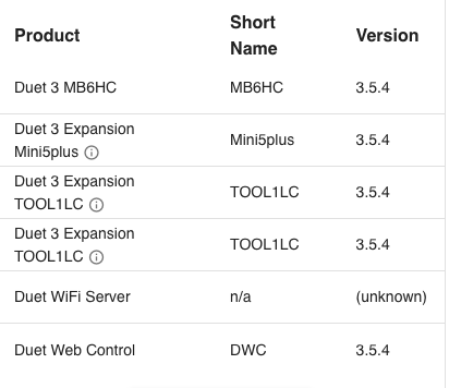
I'm currently on 3.5.4

Biggest issue I am having is with occasional 'Tool is in use or Axis is in use messages' - the biggest problem with these are that they don't stop execution so a) It can cause head clashes and b) They are quick tricky to track down.
I got a surprising tool temperature requirement - absolute zero - which I need to try and track down the cause.
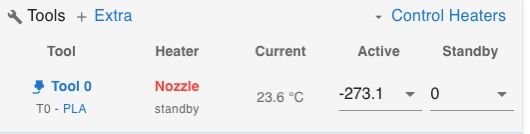
UPDATE: Solved this issue - I had missed out the S on my M568 - so just had 0 - handy to know for the future.Also I am getting some quite strange behaviour with the U and Z axis - where sometimes when I do a Z move down it seems to also move U left (probably to where X currently is).
If I then move Z up again and U right - it goes a lot further than I am asking - presumably back to its proper position.
It's interesting seeing the head move in 45 degrees - but it is messing up my probing.
See <<< on line 74 in here for the place where it does the strange move.
Update - Solved - I removed all T0 and T1 commands from alignment/homing/cleaning sequences and that seems to have stopped the odd behaviour.
It left the possibility of parts of the macro's being multi threaded by replacing all T0,T1's with M596.1 T0/T1 - which will still do the tool switches when needed.;AlignUVZ.g ; if exists(global.ballProbeX) == false abort "XY alignment not found" G90 G1 Z50 F10000 T0 G1 X30 Y30 F20000 M400 M98 P"0:/macros/FindProbeUV.g" M574 Z1 S2 K3; Set Z to Ball Probe G1 H4 Z{global.zHit-1} F300 if sensors.probes[3].value[0] = 0 echo "Probe not found" break ;G1 U204 V149 F10000 T1 ; Find basic Z position var Zpos = {50,49,48,48,48} var Zrate = {300,200,100,100,100} var Upos = {10,8,8,8,8} var Vpos = {10,8,8,8,8} var UVrate = {1000,800,300,300,300} var prev = false var pVM = 0 var pUM = 0 var VM=0 var UM=0 while iterations < 2 M574 Z1 S2 K3; Set Z to Ball Probe G90 G1 Z{var.Zpos[iterations]} F300 G91 G1 H4 Z-12 F{var.Zrate[iterations]} ;echo "Z", {move.axes[2].userPosition} var ZP = move.axes[2].userPosition G1 Z5 F5000 M574 Z1 S2 K0; configure Z axis endstop ; Now find U middle G91 G1 U{0-var.Upos[iterations]} F5000 G90 G1 Z{var.ZP-0.2} F300 G91 M574 U1 S2 K3 ; Configure U axis with Z ball probe G1 H4 U+10 F{var.UVrate[iterations]} ;echo "X1", {move.axes[0].userPosition} M400 var U1 = move.axes[3].userPosition G1 Z5 F300 G1 U{var.Upos[iterations]} F5000 G1 Z-5 ; <<< Strange move - where it also moves U back M400 G1 H4 U-10 F{var.UVrate[iterations]} ;echo "X2", {move.axes[0].userPosition} M400 var U2 = move.axes[3].userPosition G1 Z5 G90 set var.UM = (var.U1+var.U2)/2 ;echo "XM", {var.XM} G1 U{var.UM} M574 U2 P"!122.io0.in" S1 ; configure U axis endstop ; Now V G91 G1 V{0-var.Vpos[iterations]} F5000 G1 Z-5 F300 M574 V1 S2 K3 G1 H4 V+10 F{var.UVrate[iterations]} ;echo "Y1", {move.axes[1].userPosition} M400 var V1 = move.axes[4].userPosition G1 Z5 F300 G1 V{var.Vpos[iterations]} F5000 G1 Z-5 F300 G1 H4 V-10 F{var.UVrate[iterations]} ;echo "Y2", {move.axes[1].userPosition} M400 var V2 = move.axes[4].userPosition set var.VM = (var.V1 + var.V2) / 2 echo "UM", {var.UM},"VM", {var.VM},"ZP", {var.ZP},"---U1,2",{var.U1},{var.U2},"--V1,2",{var.V1},{var.V2} if (var.prev == true) echo "variation U:",{var.pUM-var.UM}, "V:", {var.pVM-var.VM} set var.pVM = var.VM set var.pUM = var.UM set var.prev = true G1 Z5 F300 G90 G1 U{var.UM} V{var.VM} F2000 M574 V2 P"io4.in" S1 ; U Axis optical M574 Z1 S2 K3; Set Z to Ball Probe G91 G1 H4 Z-5 var Z1 = move.axes[2].machinePosition echo "z1",{var.Z1} G1 Z5 F1000 G1 U4 F10000 G1 H4 Z-10 var Z2 = move.axes[2].machinePosition echo "z2",{var.Z2} G1 Z5 F1000 M574 Z1 S2 K0; configure Z axis endstop if var.Z1-var.Z2 < 1 echo "z1,z2",{var.Z1},{var.Z2} abort "possible issue with UV alignment" G90 var adjust = var.UM - global.ballProbeX echo "adjusting U",{global.ballProbeX - var.UM},"V",{global.ballProbeY - var.VM} G92 U{global.ballProbeX} V{global.ballProbeY} if exists(global.UVAdjusted) == false global UVAdjusted = trueI have written a little wrapper macro form M596 - M596.1 - which a) Has the ability for M596's to be switched off, and be allows the tool to be specified instead of the motion system.
NB/ At present my tools and motion systems are swapped round - i.e. T0 is in motion system 1, and T1 in ms 0 - This was due to issues I was having when I have a servo on T1 (UV axis) - so I may well swap them back around at some point.
;M596.1,g ;M596.1 P-1 ; Ignore M596.1 commands until P-2 if exists(global.M596_stat) == false global M596_stat = -1 if exists(param.P) if param.P < 0 set global.M596_stat = param.P else if global.M596_stat == -2 M596 P{param.P} if exists(param.T) && global.M596_stat == -2 if param.T == 0 M596 P1 T0 else M596 P0 T1 if exists(param.Z) && global.M596_stat == -2 M596 P0 T1 -
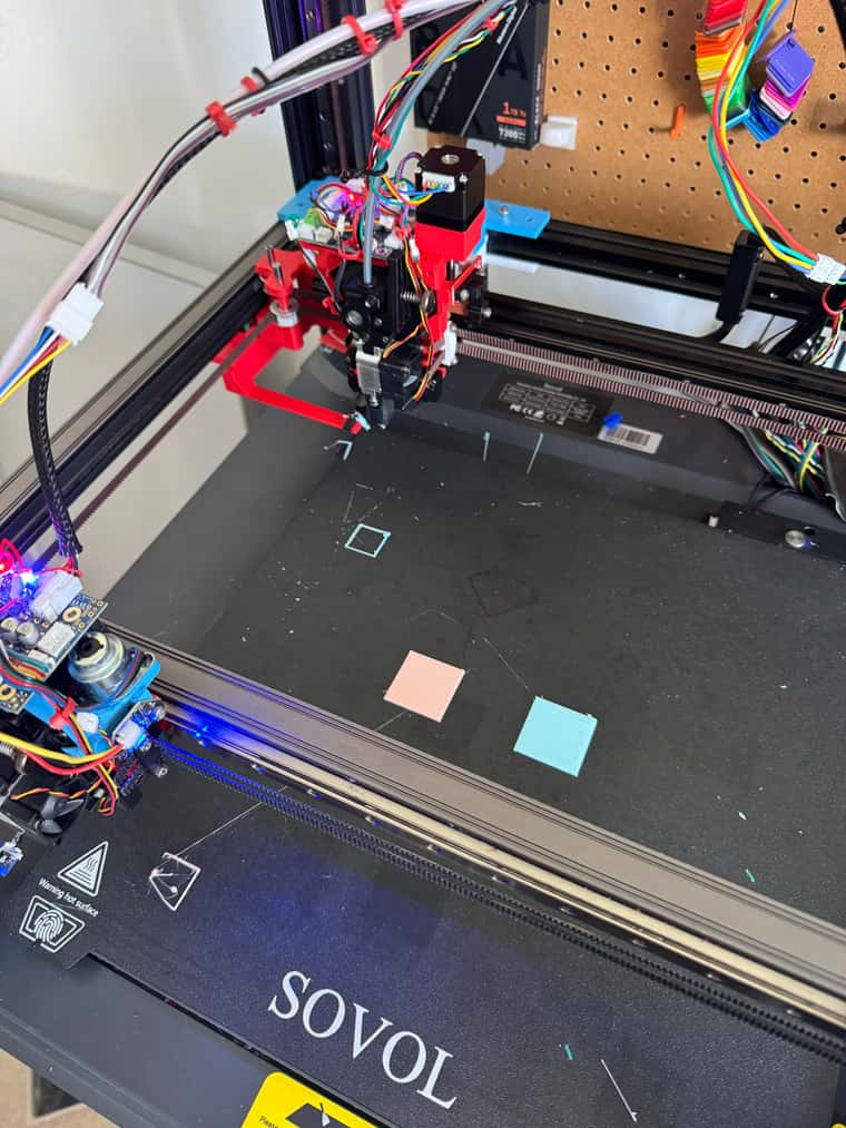
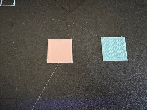
Ball probe Auto Alignment getting fairly good.
Images of nozzle as was found by printer with no manual adjustment or head movements.
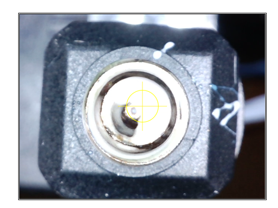
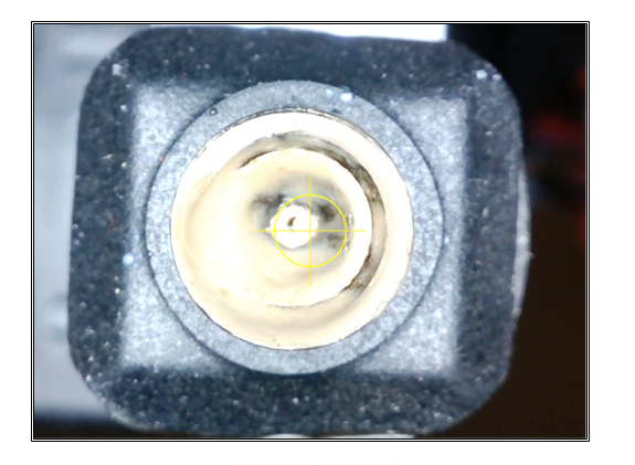
The alignment isn't perfectly on the centre of the nozzles in the camera because I can't guarantee the XY offset between the camera and ball probe - due to the swing out movement based on a servo - which might be a slightly different angle every time.
Checking with the camera I am getting a 0.1mm variation in the X/U axis, and 0.7mm in the Y/V axis.
Not sure if this a consistent difference or whether it varies.Not sure if this is dirty nozzles, nozzle shape irregularity or RRF Ball Probe macros' or just the sort of error you might get with a ball probe vs camera.
My XY Axis is still on sensorless end stops - so will be interesting to see what difference it makes swapping between sensorless and optical end stops in keeping alignment across reboots.
-
I think I just had a bright moment regarding z-hop: Re-purposing Rc-car servo savers could be the answer to more torque and accuracy, whilst still be backlash-free.
I tried to find a good picture to show how they work and came up with this:

Twisting the servo arm while the output-side is fixed to the tool head would be translated to vertical lift (or drop if you want to use gravity to your advance).
They usually come with an adjustable spring which isn't shown here.
