Sovol SV08 Multiple Motion System Upgrade.
-
@dwuk3d As long as you don't go the rotating bed route, I'm sure you'll be succesful.
It has been proven (by @CNCmodeller ) that the accelerations required to print near the center of a rotating bed are impossible to achieve. The center itself is a No-Go zone. -
@o_lampe Can't find the @CNCModeller post - although I suspect you are talking about rotary printers - with the rotary motion is one of the Axis - and when you are right in the centre you need to speed the spinning up very fast to get the same amount of motion as you would get from the edge.
I'm not proposing that - I am still proposing a normal XY type AXIS - just having rotary as mainly a way of moving parts of the bed to different places within the print head envelope to allow better coverage / more parallel printing.
Continuous rotation would be nice too - to allow things like parallel vase mode prints.
-
@dwuk3d said in Sovol SV08 Multiple Motion System Upgrade.:
Can't find the @CNCModeller post
Hmm, me neither. Maybe he was so succesful with it, that he went closed source ?
I only found this early photo of polar printer
Parallel Vase mode would be cool, but when I made things in vase mode I already had to slow down a lot, because of the minimum layer time/part cooling.
With multiple heads you'd also have to sort out a precise method to sync layer times, unless the part is super symmetric. But with such a part, you can just split it in vertical halfes (or quarters) and use mirror mode on a stationary bed. -
@o_lampe yes you are right about needing to sync layer times.
I will probably do something symmetrical like a sphere first - but to really demonstrate the concept I want to do a really complex non symmetrical shape, with layer times syncronised by slowing down some of the heads at appropriate times.
Will want to do this on normal segmented parallel prints too - to avoid heads going idle and needing to be cooled down, parked, primed and reheated as much as possible,
One of my earlier youtube shorts demonstrated the multi head vase mode principle.
Also Nathan Builds Robots massive printer does something like I want to do - although his design is restricted to only having in and out and up and down on each head - so would suffer from the 'centre' speed issues you mention.
-
Made a bit of progress on alignment issues - i think its a dimensional accuracy issue - and may actually be a problem with my Dual Markforged kinematics when moving in the X and Y direction at the same time.
Or might be due to the backlash compensation I put on the old V axis - which is now the X axis (W) on my third toolhead - which is the one that seems to be squashing up its dimensions a little bit when compared to the other print heads.
i need to take a break from this printer for a few days - so will address the issue later,
One big discovery I did make though while trying to resolve this - is that what I previously thought were strange hangs on things like M598's, M400's or M596's - which led me to completely stop using M598's were probably more like the fact that echo commands sometimes seem to stop working on forked multiple motion systems.
I put in loads of echo's before and after commands thinking I could see where control on each file was hanging - but worked out today that processing was actually still running in loops and commands quite a long way further into the file - usually on G4 500's in loops.
When this happen's M122 still seems to tell you the G4 or other command each file is currently on - so I have changed every G4 to have a slightly different millisecond delay time value - so that it is then possible from the M122 to work out which delay loop each forked file is currently executing.
Might start using global variables to trace current position - rather than echo's to see if that works more reliably.
Nb/ I am still on 3.5.4 - will test out some of this on 3.6 at some point too.
-
Another issue I have is with the probe moving a bit - I've changed a few things - but it is still not perfect. I have been considering changing from using a servo to a stepper - I think a fairly big Nema17 might hold the probe more steady in the Y direction or I could try a Nema23. The magnet is probably better at holding it in place in the Z direction. I might try also trying so somehow interlock something into the indentation of the magnet when it pulls down - to also prevent Y movement.
Re rotary bed
The next challenge after that is bed coverage by each print head.My current thinking is once per layer rotate the bed 90, 180 and 270 degrees. - I will be rotating a square rather than round bed.
That should allow all 3 heads to access the whole bed, plus allow parallel printing.
If i only rotate it like that and then rotate it back again then I won't have any wiring issues - but I would also like to try making in continuously rotate capable like yours - so that I can do 3 headed vase mode prints.
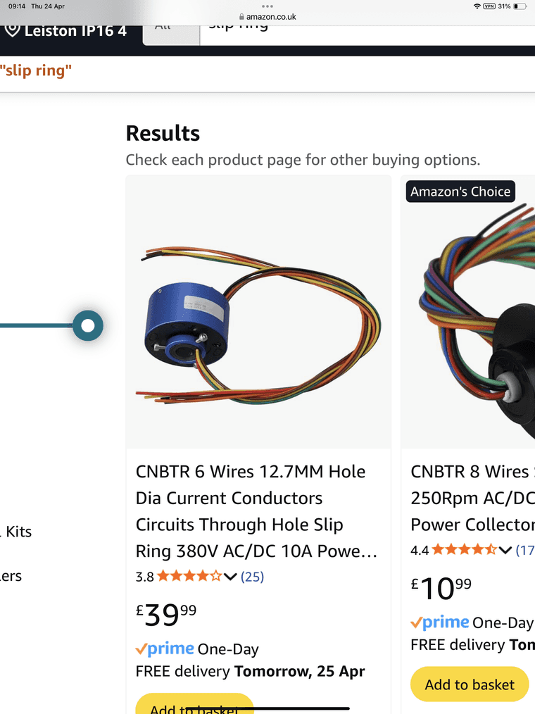
I think i will need a 4 way slip ring for this capable of mains power - any thoughts on this.
I suppose I could go 2 way - just for the bed heater - and try using something like an IR temperature sensor for temperature - but not sure whether the PWM or whatever stuff would handle that.
-
Some inspiration for adding further features to my printer after looking at this very impressive video
https://youtu.be/M51bMMVWbC8?si=kyLhSQ2Y6XhIFs34
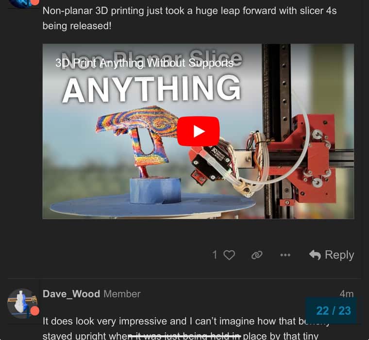
It does look very impressive and I can't imagine how that benchy stayed upright when it was just being held in place by that tiny chimney and filament was be added to the benchy in a horizontal direction,
I'm going to try and simulate his printer with his slicer in blender - should hopefully result in some interesting animations.
What interests me probably more than the non planer aspects - is the concept of printing onto the side rather than top of objects - which I think could bring a lot of efficiencies to multi colour printing.
As you only really need the colours on the outer surface - and so would be able to print most of the structure of an object in a single colour like white - and then colour it in with a few passes of the different colours applied to the top, bottom and sides.
Perhaps using a multiaxis printer like in the video, or maybe with something to rotate the print around in more dimensions instead.
I'm going to be adding rotary movement as the next stage of my multi head SV08.
This video inspired me to maybe allow at least one of the print heads to pivot up to a bit of an angle - rather than always facing downwards - and then use it to print onto the side of objects - rotated to the appropriate angle.
-
@dwuk3d What puzzles me is: he prints without a heated bed and he's able to print at the center of a rotating bed.
And he doesn't even mention this, like it's a common thing.I'd like to see some prints with single colour filament, just to see how clean the surface looks. IMHO, there are way to many artifacts, but they're obscured with pixie dust filament
")
-
@o_lampe I do a lot of my long prints without heat on a Bambulab cool plate - mainly to allow for long overnight or out of the house pauses. Bed adhesion for PLA is actually so good I can't use it for small fragile things.
I'm going to make mine heated though from the outset - and just use the standard SOVOL square build plate - perhaps with the corners chopped off if it won't quite rotate.
I notice now on relooking at the video that he has a very wide brim around the chimney - and some of his other prints look ok - so I wonder if the artifscts you noticed are due to wobble because of the very thing chimney.
When printing the sails of my very tall Sea Cloud model (see youtube) I had to add braces between the sails at a few heights to stop the wobble.
You are right about that filament hiding print quality defects - I was actually thinking of purchasing 3 rolls of it for my printer for when I get on to some big parallel prints - as I thought it might hide the joints a bit.
Re printing in the centre - I think it is possible - but just extremely slow. I got the impression that the non planer solution demonstrated is pretty slow - even for the outer parts.
-
Youtube response about probing.
there is quite a lot more work required to get really good bed levelling.
At present it does 3 stages all only using inductive probes at the moment.- Initial Z homing on the front extruder inductive probe only.
- 4xZ axis motor adjustment using front inductive probe only.
- Rear right inductive probe based Micro Z alignment vs front micro Z alignment using the two inductive probes.
What I need to add is
- Use of the inductive probe on the new 3rd print head
- Use of the Z height values from the ball probe
- Bed mesh probing from one or all of the inductive probes.
- I also have an eddy probe for fast bed meshing which I haven't deployed yet.
- I can also do 'voron tap' type probing by lowering each head to actually touch the bed and then use the optical sensor on each head. I did this for one of the heads - but it all got a bit too confusing - but ultimately I think that type of probing is going to be more accurate than the inductive probes.
Also all probing is currently one probe at a time - whereas i think there are some opportunities for doing some things in parallel.
-
Quite pleasantly surprised to find that slip rings not as expensive as I was expecting - this one for example looks to me more than enough for my needs
Re -print head alignment / dimensional accuracy- I'm think I might get a second ball probe to have on the same arm - with the camera in the middle.
I could then probe each head 4 times - with the arm in two positions.
Should from this be able to get pretty accurate dimensional accuracy /adjustment info.
All of the probing points will need to be in the central area where all of the heads can reach,
Might even be able to do two lots of probing at the same time if I can make the heads as thin as possible in the X direction.
Will also switch over the servo to a stepper motor.
-
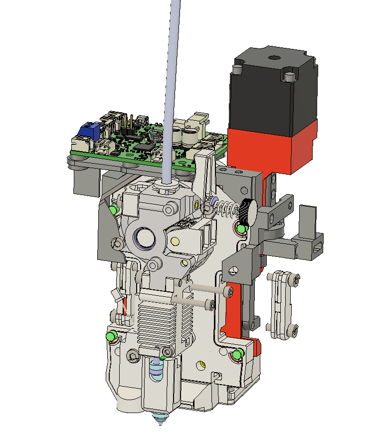
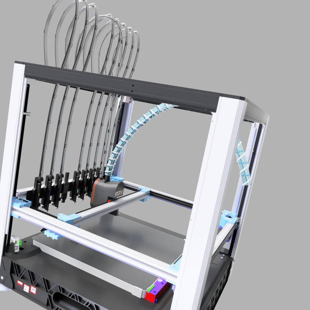
Think I might need a Roto toolboard for when I add an INDX to my front gantry.
Nb/ my picture of the INDX toolhead is slightly bigger than the real thing according to Bondrech.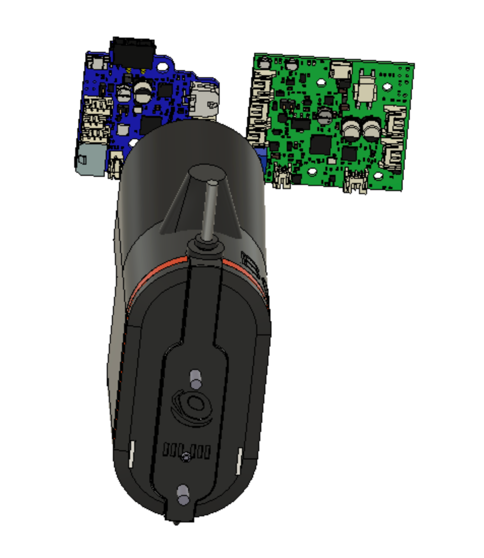
Might get one now as it could also help with reducing the width on my rear right extruder too - although I suppose I could just rotate the 1LC upwards so that it doesn't take up so much space.
-
I wouldn't use a slip ring for a heated bed. At least I wouldn't trust the Chinese specs too much.
Maybe you can get away with it by using a 230V heater with a SSR? But that opens another rabbit hole. -
@o_lampe the bed is already mains with an SSR - so I was planning on putting the SSR output through the slip ring, plus the temperature sensor.
Are you saying that would be ok - or that I should look at a better quality slip ring?
I suppose continuous rotation would only be a novelty feature - I wouldn't need a slip ring for 90,180,270,180,90,0 rotation - which is the main reason fir me adding it.
So I could drop it if a good quality one is going to be massively expensive,
I could always disconnect the cables and use a bambulab cool plate for continuous rotation demo's.
-
@dwuk3d Almost forgot the thermistor....If you can, double up the lines for it, to reduce false readings from bad slip ring contacts.
If you already use an SSR, you know the possible downsides of bang-bang bed heating. I did that for a long time and it didn't bother me.A more general concern is your project-philosophy, if I may critize you.
As a former project manager, I know it's important to set three things before you even start:- define a goal (and stick with it)
- define a timeline (not so important here)
- define a budget
Especially ignoring the first one often leads to unfinished projects...just saying
")
-
@o_lampe thanks good idea about doubling up - that slip ring has 6 connections and I only need 4 - so I can double up the heater ones - 20A 230v would be masses more than I need.
I haven't done enough actual printing on the SV08 to find any heat bed issues - but it seems to maintain temps ok - although I did get a failure with the PID tuning,
Point taken about the project approach.
One of the advantages of not having a sponsor is not being restricted to specific goals, dates or budgets.
But you might be right that there is a risk of me losing interest in the project - especially as I've just booked a QM2 cruise - so really want to do a model of that ship before I go - so that I can get some comparison photos.
So far all of my changes are just reordering things that were already in the plan (or when better technology like INDX vs Stealthchanger comes along).
On this subject though I am about to change around my bed slinger approach a fair bit to not have a longer bed - but instead just move about 150mm - and add the ability to link multiple SV08's with this ability together - to get 350x700 or 350x1050 for example - with the build plates slightly overlapping the heated beds.
Will probably do dual gantry - but only single heads on the second SV08.
That will then deliver my original plan (and most popular video so far) - see Prusa Multi Mini.
My immediate plans (which I may change)
- Get 3 headed build working well - with fully parallel, faster printing
- Rotating bed
- Angled extruder on rotating bed
- 150mm bed slinging
- 2nd linked or independent SV08 with 150mm bed slinging
- 4th print head - probably on stealthchanger to allow for offloading.
- iNDX - which may slot in earlier if previous steps go past December.
-
Still away - so no progress on actual printer.
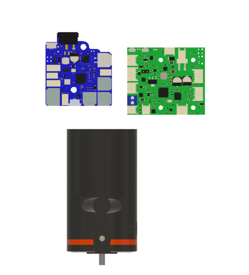
A few more Bondtech INDX diagrams (Renders from Autodesk Fusion) - with some options of where to place the PTFEs.
Might actually be better turning the whole thing around and having the PTFEs on the back with the head reversed on the rear gantry.With the front gantry having the IDEX Sovol print heads on it.
With PTFE's starting at the front of the flying gantry.

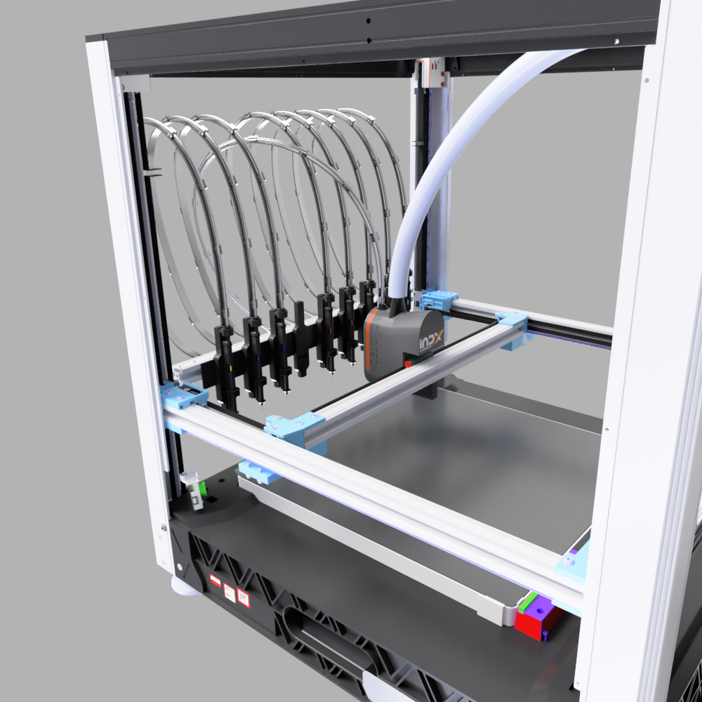
with PTFE's starting at the top.


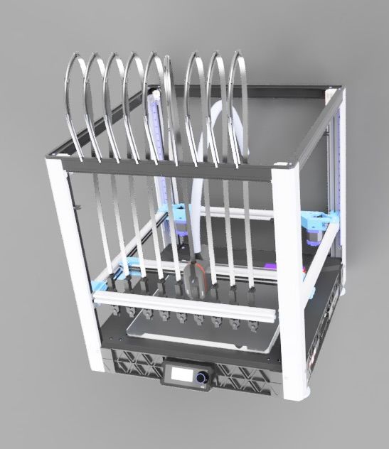

With improved modelling of the air pipe.
-
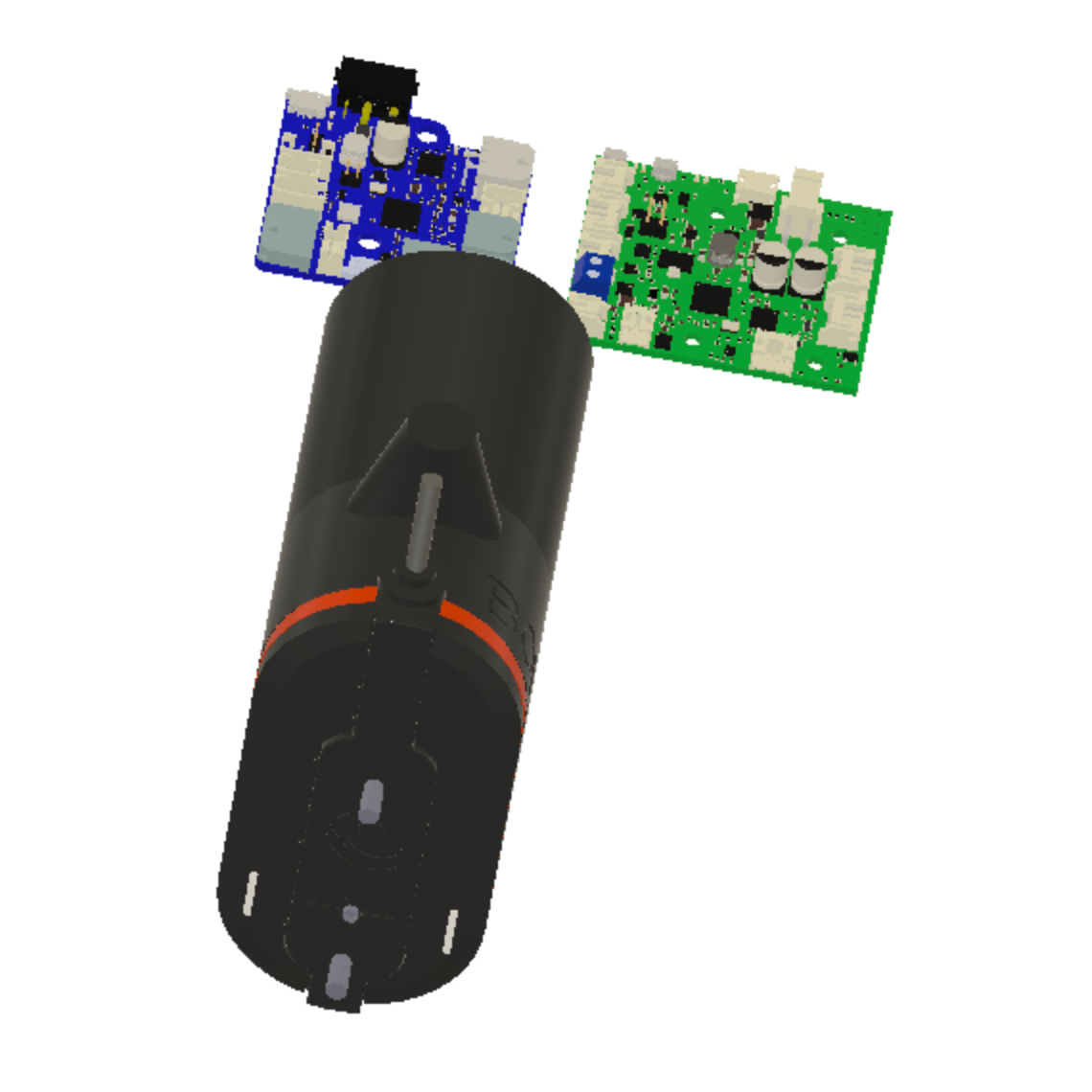
Having trouble getting the same Hanpose Nema11 x 28 lead screw motors for last extruder in a reasonable time.
Considered ordering normal Nema11's, couplers and lead screws.
But decided to go for these instead - will have to take them apart and cut down the lead screw - but delivery in a few days.
I also get a free linear rail and carriage which might be useful -Also ordered a second ball probe for dimensional alignment


-
@dwuk3d said in Sovol SV08 Multiple Motion System Upgrade.:
@droftarts Will be interesting to see if the video gets much pick up as it is certainly a very elegant design and could completely remove the need for me to add single nozzle multiplexing on top of tool changing - plus also remove the need for lots of electronics and motors etc. for the extra tools and multiplexer
Might do a better version of the video with a few animations of the different options next.
Finally got round to starting on some INDX/SV08 animations - which will eventually include my currently planned 2 Gantry, 3 Toolhead, rotating bed version - with some full multi colour ship print simulations.
Blender is very powerful - but I find it very hard to use compared to Fusion - I find I have to google at least half of the commands, including ones I have used only a few minutes ago - due to the odd keystrokes with combinations of modifier keys.
Doesn't help too that I am using a Mac - whereas most of the documentation and explanation videos use the windows versions of the keystroke modifier keys.

The INDX on SV08 renders I did last week got retweeted by both SOVOL and BONDTECH which was good.
-
Started making some progress on the Trindex SV08 printer again.
Did some simple size test prints - and started getting issues with Z offsets.
I think I will have to improve my Z alignment - either by using 'voron tap' on all of the tools, or possibly using the ball probe Z offsets.
Plus a more serious issue.
When serial 3 headed printing - but with parallel print priming and colour switching between T1 (UV) and T0 (XY) - T0 consistently layer shifts about 10mm in the X and 5mm in the Y - and the layer shift if quite fast.
I had this issue a while ago and thought it was related to the Z hopper - but I have turned the Z hopping off on XY and are still getting the issue.
If I do similar prints with T2 (WV) and T0 (XY) - both of them print fairly well.
I have seen some oddities in normal alignment testing with X and Y sometimes jumping when I switch between tools - so not sure if it is an issue with my config, macros, slicer GCODE or a 3.5.4 problem.
Will continue investigating to try and get the problem to occur in a more simple gcode file without parallel printing.
Or might just try setting up another tool - T3 - and assign that to the UV - to see if I get the same issues.