Sovol SV08 Multiple Motion System Upgrade.
-
@dwuk3d said in Sovol SV08 Multiple Motion System Upgrade.:
Plus a more serious issue.
I might have to do with endstop offset adjustment.
-
@o_lampe thanks - do you mean G92's.
I don't think I have any of those in my macros that would be invoked mid print - the problem occurs mid layer 2 = when the printing switches back between T1 to T0. But I will check.
I think though that something is changing the endstop offsets for the Y and Y axis and then jumping them quickly to the new position.
I have noticed some unexpected behaviour when moving around between tools and mapped axis - but haven't really found a way to recreate the issue.
If I don't manage to resolve the problem I suppose I could try removing the X and Y mapping completely from the T1 and T2 tools definitions , and instead post process the G0-G3's to specify U,V & W instead when using T1 or T2.
Ps - the sequence is
Homing.z offsets
Motion system 1 - layer 1 - print T0 section ok
Motion system 0 - layer 1 - wait for pre-heat, delay, preheat, T1 print prime, wait for print T0 to finish, T1 print layer 1, move Z up to layer 2, T1 print layer 2.
Motion system 1 - layer 2 - wait for pre-heat, delay, preheat, T0 prime for layer 2, wait for T1 to finish, T0 head jumps to incorrect position, T0 print layer 2 - with layer shift -
@dwuk3d said in Sovol SV08 Multiple Motion System Upgrade.:
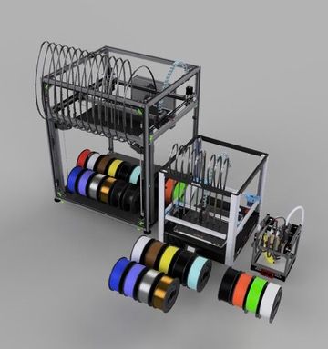
Finally got round to starting on some INDX/SV08 animations - which will eventually include my currently planned 2 Gantry, 3 Toolhead, rotating bed version - with some full multi colour ship print simulations.
Nice animations!
Blender is very powerful - but I find it very hard to use compared to Fusion - I find I have to google at least half of the commands, including ones I have used only a few minutes ago - due to the odd keystrokes with combinations of modifier keys.
I keep shying away from learning Blender, but then I don't need to animate or simulate anything; Fusion 360 does everything I need for now. I know some people use Blender for all their CAD work, but that seems a bit masochistic.
Doesn't help too that I am using a Mac - whereas most of the documentation and explanation videos use the windows versions of the keystroke modifier keys.
I use a Mac too. So far, Fusion 360 has worked well, I haven't had any issues. A couple of years ago I was running it on an 2013 MacBook Pro, where performance was lacking when working with large models and rendering, so updated my desktop PC (I7-10700K with RX 6600XT - runs Windows 10/11, Linux, and MacOS with OpenCore), but after spending a long time trying to get it to run well, I ultimately bought an M2 14" MacBook Pro, which has been brilliant. Haven't turned on my PC for a long time! If I need to test something in Windows, I use Windows 11 ARM on VMware Fusion.
The INDX on SV08 renders I did last week got retweeted by both SOVOL and BONDTECH which was good.
Nice, fame at last! Maybe they could send some dev kit your way.
Ian
Bed-slinger - Mini5+ WiFi/1LC | RRP Fisher v1 - D2 WiFi | Polargraph - D2 WiFi | TronXY X5S - 6HC/Roto | CNC router - 6HC | Tractus3D T1250 - D2 Eth
-
@droftarts Yes I really like Fusion 360 too.
I did try doing a whole ship model in Blender - mainly due to the perspective corrector add-on - which is a really good way of tracing 3d objects when they are at an angle or have perspective distortion.
Ultimately though I gave up when print quality wasn't as good, plus having the spend ages wrestling will the models to correct model mesh errors.I'm still using a 2020 MacBook Air 8gb M1 - and it works pretty well - although it really started to struggle with this combined model - which I know would work easily in Blender. - I might upgrade to an M4 at some point with a larger screen for when I am away.
I got a PC too mainly for rendering of animations - which are about 60x faster on the 4070 Super/Ryzen7950X3D/32GB - vs the M1 GPU. Blender runs slightly quicker on Linux - but I usually do my rendering in windows 11.
Put up a couple more videos with a bit more detail, one of which got retweeted by Sovol - so fame building further. What would be really good though is if Sovol (or someone else) gets together with Bondtech to release a fully built, tested and supported INDX printer.
Free stuff might be nice - but I think it changes it from being a hobby - and starts putting pressure on to deliver. I haven't applied for the Bondtech Beta Programme as don't want to be sworn to secrecy.
PCBway have been in contact too about the triple headed printer videos - I guess having their logo on would add a certain amount of Kudos - but I don't think I need any custom PCBs - might need some CNC stuff though when I got to the rotary bed phase - but probably won't pursue it.Makerworld Boost points are pretty handy though for filament, plus Bambulab are selling quite a lot of parts too now. Plus might partially pay for an H2D if I decide to go for one. It's not until you try and create a printer do a major upgrade that you realise how much work must have gone into the X1C to make it so good.
-
Back to printer -
New Z Hopper motors arrived - bought full linear actuators - which I will take apart - as seems to be most cost effective way to source Nema 11 lead screw motors

Tap sensoring now working.
Logic is
1.Home All
2. G32 Z motor alignment
3. Then for each print head
4. Move other print heads 2mm up so that they are out of the way
5. Align Z hopper to just trigger optical sensor
6. Move head down about 0.02 mm to just past the trigger point.
7. Switch probes/endstops so that the Z axis now has the Z hopper end stop as its trigger. (inverted)
8. Move Z down until print head hits to bed and then pushes up slightly within the play of the print head to disable the triggered optical sensor.
9. Repeat for various points of the print bed,Short demo - showing tapping and play/flex - which might end up being a problem
https://youtu.be/5FGALqWV4t8Example Tap test macro.
;tap A.g M98.1 A"B On" ;reset probes to correct values M574 Z1 S2 K0; configure Z axis endstop M574 A1 P"122.io2.in" S1 ; configure A axis endstop G90 G1 Z3 F1000 G1 D{global.dOffset+2} F1000 G1 B{global.bOffset+2} F1000 var speed = 400 ;var w = {224, 224, 324, 324} ;var v = {310, 210, 210, 310} var w = {160, 200, 200, 160, 324} var v = {160, 160, 240, 240, 310} var point1 = -1 while iterations < 5 var iGrid = iterations G1 W{var.w[var.iGrid]} V{var.v[var.iGrid]} F10000 ;echo "W",var.w[iterations],"V",var.v[iterations] while iterations < 2 M574 Z1 S2 K0; configure Z axis endstop M574 A1 P"122.io2.in" S1 ; configure A axis endstop var aMax = 0 var aPos = 0 var aMin = 99 while iterations < 1 G1 A3 F{var.speed} M400 var aProbe = sensors.endstops[6].triggered if var.aProbe abort "A Probe already triggered" G1 H4 A-2 F{var.speed} set var.aPos = move.axes[6].machinePosition ;echo "D trigger pos",var.dPos if var.aPos > var.aMax set var.aMax = var.aPos if var.aPos < var.aMin set var.aMin = var.aPos var aProbe = false if var.aMax-var.aMin > 0.03 echo "variation",var.aMax-var.aMin,var.aMin,var.aMax while iterations < 4 ;echo "i",iterations G1 A{var.aPos-0.01*iterations} F{var.speed} M400 set var.aProbe = sensors.endstops[6].triggered if !var.aProbe abort "A Probe not triggered" else if iterations > 1 echo "lowered head ",0.01*iterations,"mm" break M574 A1 P"122.io3.in" S1 ; configure A axis to temporary Endstop M574 Z1 P"!122.io2.in" S1 ; configure Z Axis to A end stop inverted var zPos = 0 G1 Z{var.zPos+2} F500 M400 set var.aProbe = sensors.endstops[2].triggered if var.aProbe abort "AZ Probe already triggered" G1 H4 Z-7 F{var.speed} set var.zPos = move.axes[2].machinePosition if var.point1 == -1 set var.point1 = var.zPos echo "A zPos",var.zPos,"W",var.w[var.iGrid],"V",var.v[var.iGrid],"point",var.iGrid,"var",var.zPos-var.point1 G1 Z3 F1000 ;restore probes M574 Z1 S2 K0; configure Z axis endstop M574 A1 P"122.io2.in" S1 ; configure A axis endstop ; 122.io3.in - dummy endstop when A swapped out -
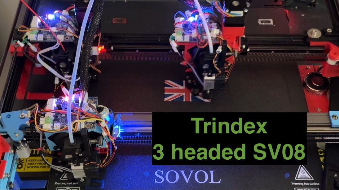
Printing getting better. I don't think the original problems with the flag in the video a few months ago were dimensional inaccuracies or alignment issues - rather the fact the it was cutting off some of the colours due to Axis limits.

-
Z offset Tapping now working quite reliably as long as the print heads are clean.
Lots more work to do on timings and speed, and print head design - but printer starting to come together.
-
@dwuk3d One of the first multicolour prints we did at RepRapPro with the Tri-colour Mendel, around 2013/14, was a Union Flag!

I don't have any pictures of the print, but the files are here: https://github.com/reprappro/Interesting-3D-Prints/tree/master/RRP Union flag2
Our other favourite was the multicolour frog: https://www.thingiverse.com/thing:329436
Ian
Bed-slinger - Mini5+ WiFi/1LC | RRP Fisher v1 - D2 WiFi | Polargraph - D2 WiFi | TronXY X5S - 6HC/Roto | CNC router - 6HC | Tractus3D T1250 - D2 Eth
-
@droftarts Cool - looks like that 3 colour printer predates the Prusa MMU1 by quite a lot.
-
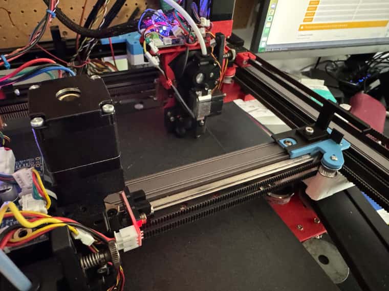
Front extruder now rebuilt with Nema11.
Had to cut some of the shaft off, and I think I can bring the motor down about another 13mm if I cut more of the shaft off.
All heads now being on Nema11's should now enable proper Z hopping and (with the aid of a post processor) some independent Mesh adjustment.
Also moved the front extruder off of sensorless homing on to Optical End stops.
With the X and B (Z Hopper) Axis sharing a single sensor.


Did find one tiny issue - I accidentally used the wrong filename homeb.g instead of homex.g when I was creating my new optical end stop file - I had previously renamed the homex.g to homex_sensorless.g
Instead of telling me the homeb.g file already existed I think it just wiped it out - so I had to recreate it from scratch.
Also - when switching endstops between different Axis I am finding that in order to release an end stop from the old Axis and need to give it another one - so I am using one of the unused io[x].in from one of the boards to swap that into the old axis end stop - so that it releases the end stop - so that I can assign it to the new Axis.
Not sure if this is the best way to do it - especially as I am gradually using more and more of the io[x].in's for things.
-
@dwuk3d said in Sovol SV08 Multiple Motion System Upgrade.:
Also - when switching endstops between different Axis I am finding that in order to release an end stop from the old Axis and need to give it another one - so I am using one of the unused io[x].in from one of the boards to swap that into the old axis end stop - so that it releases the end stop - so that I can assign it to the new Axis.
Just set the endstop position to 'none' in M574, e.g.
M574 X0will release the IO input that was previously used by the X endstop.Duet WiFi hardware designer and firmware engineer
Please do not ask me for Duet support via PM or email, use the forum
http://www.escher3d.com, https://miscsolutions.wordpress.com -
@dc42 Thanks will try that
-
Still having issues with Multiple motion systems and layer shifts.
It went away for a while - but it has now moved from T0 to T1 - during parallel priming.
I thought it might be due to my priming being in a replacement command Macro - M801.
M801 moves the print head - and then it seems to return back to where it was before calling the macro - sometimes quite fast.
So I changed the Macro that calls M801 to pre-position the print head where it will end up after the M801 before calling it - and that has reduced the unexpected moves.
Still getting the issue though where on the 3rd perimeter of the T1 priming cycle (which is in parallel to T0) the print head rapidly moves to the wrong place.
I wonder if it is macro related.
Update - found a pattern I think
What is happening is the on motion system 0 - T1 is priming
On motion system 1
T0
--Park XY Macro
----M800 - which moves the T0 Z Hopper B Axis up
----T0
----Move X&Y out of the way
---M800 - which moves to T0 Z Hopper B Axis down.If I change M800 so that it doesn't move the B Axis then I don't get the issue.
Or if I remove the M800's from ParkXYI think the B Axis is somehow related to the problem I had with tool 0 also.
Tool and Axis definitions attached below
; Smart Drivers M569 P0.0 S1 D2 ; driver 0.0 goes forwards (Z axis) M569 P0.1 S1 D2 ; driver 0.1 goes forwards (Z axis) M569 P0.2 S0 D2 ; driver 0.2 goes backwards (Z axis) M569 P0.3 S1 D2 ; driver 0.3 goes forwards (X axis) M569 P0.4 S0 D2 ; driver 0.4 goes backwards (Y axis) M569 P1.3 S1 D2 ; driver 0.5 goes backwards (Z axis) - changed to 1.3 forwards ;M569 P1.0 S0 D3 V2000 ; driver 1.0 goes backwards (U axis) ;M569 P1.1 S0 D3 V2000 ; driver 1.1 goes backwards (V axis) M569 P1.0 S0 D2; driver 1.0 goes backwards (U axis) M569 P1.1 S0 D2 ; driver 1.1 goes backwards (V axis) M569 P1.4 S0 D2 ; Z-hopper 2 M569 P0.5 S1 D2 ; Z-hopper 1 M569 P1.5 S0 D2 ; VH Axis Left M569 P1.6 S1 D2 ; VH Axis Right M569 P1.2 S1 D2 ; U AXIS Z Hopper M569 P121.0 S0 D2 ; driver 121.0 goes backwards (extruder 0). X M569 P122.0 S0 D2 ; driver 122.0 goes backwards (extruder 1). C M569 P123.0 S0 D2 ; driver 123.0 goes backwards (extruder 2). U ; Motor Idle Current Reduction M906 I30 ; set motor current idle factor M84 S30 ; set motor current idle timeout ; Axes M584 X0.3 Y0.4 Z0.1:0.2:0.0:1.3 U1.0 V1.5:1.6 W1.1 A1.4 B0.5 D1.2; set axis mapping ; Tools ; X:Y:Z:U: V:W:A:B:C:D ; 0 1 2 3. 4 5 6 7 8 9 M563 P0 D0 H1 F0 ; create tool #0. XYB M568 P0 R0 S0 ; set initial tool #0 active and standby temperatures ;M563 P1 D1 H2 F2 ; create tool #1 ;Tool T1 - Left Nozzle - 2nd Gantry as X and Y. UVD ;M563 P1 D2 H3 F4 M563 P1 D2 X3 Y4 H3 F4 G10 P1 X0 Y0 U0 V0 S0 R0 M568 P1 R0 S0 ; set initial tool #1 active and standby temperatures ;Tool T2 - Right Nozzle 2nd Gantry as X and Y. WXA ;M563 P2 D1 H2 F2 M563 P2 D1 X5 Y4 H2 F2 G10 P2 X0 Y0 U0 V0 S0 R0 M568 P2 R0 S0 ; set initial tool #1 active and standby temperatures -
Quite good progress made today.
Managed to work around the G32 Bed.g alignment issue I occasionally have, and also got the probe alignment to be fairly reliable.
Decided to push the speeds up - from 100 to 300, and accelerations up from 2000 to 6000 - all working ok and looking quite impressive.
Am now trying to fix the just in time parallel prime synchronisation - to get all colour swaps sub second.
The pre-heats from OrcaSlicer that I have specified as 20 seconds - actually vary between 9s and 21 seconds- so even if my delay calculations were perfect it is still pretty much impossible to get perfect timing that way.
So plan a - for reprints is to capture the actual time in an array that is echo'd into a file, and then use it to get precise timings for reprints.
Am also investigating simulation - some macro's seem to run - but not sure if it is possible to capture actual times.Might have to try and work out the segment print times myself in a post processor - but real printing or simulation likely to be the best solution.
Finally doing some comparison prints of the same model with an X1C - there are only 6 colour changes in my flag model, and my accelerations are still quite a lot slower (vs 10,000 on the X1C), but the good news is that my actual print is already about double the speed of the X1C print, plus also the prep time despite all of my alignment stuff is a fair bit quicker too.
Comparison video with the two prints side by side in the works.
-
@dwuk3d If you could find a way to prevent the idle tools from oozing, you wouldn't have to use reduced standby-temp. That'd save you from all the preheat hassle.
Delay calculations might give you a headache anyway if the idle tool hasn't reached standby temp when you call the preheat macro in a back2back colour change scenario. -
@o_lampe ooze prevention would certainly be handy - although quite tricky to implement on my sovol due to the fact the idle heads are still over the build plate.
I guess something like Bambulab H2D ooze protect arm would work.
Will order one of the H2D flow blockers and magnets - to see whether its practical to fit one on my toolheads
https://uk.store.bambulab.com/products/flow-blocker
https://uk.store.bambulab.com/products/nozzle-blocker-magnet-bracketIn theory it could be driven by the zhopper motor when it reaches the top of its travel - although on the h2d it is controlled be a separate small motor.
My overnight thinking on preheat is rather than getting preheat times exact I might change my reheat process to wait a little bit after the reheat to round up the reheat times to a fix number of seconds for ranges of start temperatures.
I think I am going to have to leave reheat / standby in - as some of my print heads could be idle for a long time - maybe several hours in some prints.
My current thinking on cooldown / preheat is
-
Ooz Shield and or wipe - if tool change time > x1
-
Cooldown - if tool change time > x2 seconds
-
Reheat - if cooled down
-
Extra post reheat delay to make later timings more predictable
-
Move out Ooz shield
-
Purge out burnt filament to prime tower - if tool change time > x3 seconds
-
Prime -to prime tower if tool change time > x1 seconds -
Ideally prime should finish exactly when the other tool starts moving out of the way - for sub second tool changes.
However when timings not exact it may be better to wait until the other tool head starts moving before doing the final prime wipe.Most of the above would also apply for parallel prints - where a tool is going idle for a little while - to allow the other toolhead to catch up.
I plan if possible to slow down the printer of the faster segments to where practical remove most of the idle time, and therefore avoid the need for all of the priming/preheat stuff.Other challenges I have are with prime towers - currently because I want each head to have its own independent prime tower I am creating them in macro's.
I think this will work - but it is quite a lot of work getting them to print properly - plus I also have the challenge of missed layers - where some tools are only used a few layers apart - do I keep the prime towers the same height in parallel - which for the IDEX heads might mean extra tool changes for the prime towers, or do I allow the prime towers to drop a bit lower, and then use Z Hoppers to lower down to them when needed.
-
-
@dwuk3d I came to the same conclusion regarding preheat macros:
Start them early, but don't preheat immediately. Add a delay, depending on the current tool temp.The prime tower dilemma will be an even bigger issue when you start using a moving bed.
The tower for tool x might not be there where it used to be.
In my experience it is important to have the towers at the full height, even when the tool is idle for n layers.
I began to use a windshield instead, which is a single perimeter wall around the part created by PrusaSlicer.
Not sure if that'd make it easier or worse for your printer. -
@o_lampe thanks, have never tried using windshields - I guess they have the advantage of being close to the part, protecting the part from airflow. Disadvantages I guess are a) needing to be quite large for large parts, b) hiding the part while printing, c) if single shield only then it would be difficult to 'parallel' prime.
For single material / multi colour prints on my moving be designs I guess it might be possible to swap prime towers between the heads. However for multi material I am not keen on sharing prime towers - so I guess in this case I could end up needing an impractical number of prime towers.
Made reasonable progress yesterday on synchronising timings on reprints - without yet simplifying heat up times.
One issue I did encounter though is taking in account the knock on effect of delays on later tool changes, i.e. If I reduce the delay on a tool change to stop it finishing late, I sometimes have to increase the delay on the next one to avoid that one finishing early.Still having issues with Z offsets and repeatable alignment, may have to rethink probing approach again, and probably also need to beef up the strength of my optical end stop holders and flag parts.
-
@dwuk3d Might be time to deploy the Scanning Eddy Z Probe.
Think I will put it on the front Extruder.
Looks a bit tricky wiring up the Can connections and terminations - especially when I want to add another Mini5+ board - which also wants to be terminated.


-
@dwuk3d touch mode on the SZP looks interesting.
Also only just noticed that the Roto tool board includes an SZP built in - so will probably upgrade other print heads to roto toolboards rather than adding further separate SZPs if the touch probing works out ok.
Roto boards also likely to fit better in an INDX.
Rather than adding the 2nd Mini5+ board to my printer for just the two more stepper drivers that I think I am going to need -
to avoid the complication of having to cut the track on the Mini5+ circuit board I think it might be easier to get a 2nd tool distribution board and use my existing !LC boards (that will be replaced by Roto boards) as normal stepper drivers.So the 3 head setup would then be:
6 drivers on 6HC - should switch this over to U D v1 v2 W A
7 drivers on Mini5+ - should switch over to X Y z1 z2 z3 z4 B
2 more drivers using 1LC boards - rotary and ball probe/camera deployment
2 x tool distribution boards - with 3 spare slots
1x1LC + SZP
2xRoto with built in SZP