RC Low-Pass Filter for Blower Fan
-
@dc42 Thanks again.
Earlier tonight I was playing some more with my fan and the RC-filter. I used my multimeter to measure the voltage and found something that at least to me seems strange - but maybe this is normal and I just don't know.
When I set the fan speed to 30% output voltage (after RC) never actually was 30% of Vin. It always was above it. In my case it should have been about 4V but with the RC-filter it was depending on frequency (higher frequency=higher voltage) but even at a ridiculous
F2it still was about 8V. I can imagine that this could be expected using the small resistor and large capacitor.
But I also tried without the RC-filter and this was also a little bit frequency dependent (higher frequency=lower voltage) but it never came down to 4V either. At least it got closer and was "only" 5.6V.Now what am I missing? Is a multimeter just not the right tool for this task?
-
@wilriker said in RC Low-Pass Filter for Blower Fan:
Yesterday I changed my 1kOhm resistor to a (regular) 6.8 Ohm resistor and set frequency to 100 Hz. First of all the fan spun up with this put in series on the fan wires - in contrast to before where the fan would just not run at all.
Now the problem is that at 100Hz it runs virtually only full speed all the time, no matter of what I set speed to. If I reduce frequency to 10-15Hz I can hear a difference in speeds but still I think it runs significantly faster then it it should. I did not yet measure output voltage, though.That makes sense. With the 6.8 ohm resistor, the cutoff frequency is 106.4Hz. If you did the (3) 22 ohm resistors it would have gave you 7.3 ohms, and that would give you a cutoff frequency of 99.1Hz. It is not the best option, but I was trying to get you working with what you had on hand.
The best advice I could give is to you is, use a small capacitor. Large ones are good for load surges, but not real good at light load filter circuits. I personally would use a 22uF or less cap. Then use a breadboard to figure out what would be the best option for resistor and/or inductor to use. Then after I found the perfect combo, I would solder everything together.
-
@iamturbo1978 said in RC Low-Pass Filter for Blower Fan:
That makes sense. With the 6.8 ohm resistor, the cutoff frequency is 106.4Hz. If you did the (3) 22 ohm resistors it would have gave you 7.3 ohms, and that would give you a cutoff frequency of 99.1Hz.
What difference would that have made? I mean I could easily increase frequency to 107Hz but I doubt that this would really change the fact that at any frequency above about 15Hz the fan spins virtually full speed independent of speed setting.
The best advice I could give is to you is, use a small capacitor. Large ones are good for load surges, but not real good at light load filter circuits. I personally would use a 22uF or less cap. Then use a breadboard to figure out what would be the best option for resistor and/or inductor to use. Then after I found the perfect combo, I would solder everything together.
Breadboard-prototyping is a really good hint. I even do have a breadboard but I always forget about it.

Today I bought a 1N4148 diode to first get the tacho output fed correctly into the Duet. Then I see how I proceed in this topic.
Manuel
Duet 3 6HC (v0.6) with RPi 4B on a custom Cartesian
with probably always latest firmware/DWC (incl. betas or self-compiled)
My Tool Collection -
@wilriker I'll try to make this as simple as I can, hopefully this will help.
A PWM signal only has 2 states, "HIGH" and "LOW". for this example the voltage does not matter. It could be 12V, 5V, 3.3V etc... We don't care about the voltage right now, only the PWM signal.
The PWM frequency is the number of PWM cycles in one second. If the frequency is 100Hz, then there are 100 PWM cycles in one second. Meaning, that each PWM cycle is only 0.01 seconds (10ms) long.
The duty cycle is the ratio of how long the signal is high to how long it is low.
If we have a duty cycle of 50%, the signal would be high for 0.005 seconds (5ms), then low for the remaining 0.005 seconds (5ms). If we set the duty for 30%, that would be 3ms high and 7ms low. and if we set it to 90%, that would be high for 9ms, and low for 1ms.
The common way for a PWM cycle is to start high, wait the amount of time set by the duty cycle, then go low for the remaining amount of time. Not everything follows this way, but for this example, we are not going to worry about the other ways.
Now, lets say our filter is tuned to only look at a single 10ms (100Hz) PWM cycle. It would only see the signal being high for sometime, then go low for sometime.
But now lets change the filter to look at a 9ms (106Hz) PWM cycle. It would see the high like the last filter, but the low would be shorter than the other filter.
Lets set the duet duty cycle to 50%, and the frequency to 100Hz (10ms cycle). The duet would make the signal high for 5ms, then low for 5ms. Now we add the 106Hz filter. The filter is only going to see 9ms of the PWM cycle. So that would be 5ms high, then 4ms low. That would mean the signal is high 80% of the time ((4ms/5ms)*100). That means, even though you set the duet to 50%, your fan would see 80%.
Capacitors are like water towers. They store a charge, and depending on there size, they can store a little or a lot of charge. That stored charge takes time to discharge. Larger caps take more time to discharge, just like water towers. Everytime the PWM signal goes high, the cap gets charged. And every time the signal goes low, the cap gets discharged. How much discharged depends on the load, your fan for example. If the cap cant discharge most of the energy before the next PWM cycle, the cap gets recharged before it can discharge. If you keep putting in a 80% PWM duty cycle into a cap, but only using 40% of the energy, the cap would be fully charged in only 2 PWM cycles or 20ms. That is why your fan stays on no matter what duty cycle you set. And that is why the lower frequency helped, there was more time for the cap to discharge.
The advice I gave you before was me trying to get what you had on hand to at least help you. Without some kind of feedback from the fan, and a circuit to monitor and adjust the PWM on the fly automatically, you are not going to be able to get a direct correlation between the speed you set, and the actual speed of the fan.
What I did is with my old ramps board is is found a R-C combination that removed the PWM noise from the my fan using the smallest cap I could use. I used a 100uF cap, and a 10Ω resister on a fan that has a 0.25A rating. If my fan used less power, I would have used a smaller cap.
Hope that helped.
-
@iamturbo1978 First of all a big thanks for this very detailed explanation.

I knew parts of it but there was some very interesting news in it.Especially that the PWM high-low-cycles are always within a cycle that is defined by the frequency. Up until now I always thought that it would combine the latter type of cycles to continues high and low phases. But the way you describe it makes a lot more sense because otherwise you would loose a lot of fine-control at very low frequencies.
Also finally I understand cut-off frequency of the RC-filter.
With one open question though: you say if we have 10ms cycles and a 106Hz filter will only see 9ms of these cycles - what happens with the remaining 1ms? A friend of mine just proposed that it will "stretch" what it sees to match the "outer" cycle, i.e. it will create a 10ms cycle out of what it sees but using the proportions it sees in 9ms.I guess I finally have to buy a book on electronics.

Manuel
Duet 3 6HC (v0.6) with RPi 4B on a custom Cartesian
with probably always latest firmware/DWC (incl. betas or self-compiled)
My Tool Collection -
There is a complication which makes the R-C filer much worse in this application. The output of a Fan connector is not a square wave with a variable mark-space ratio. It is a switch (the mosfet) that alternately connects the load to V_Fan and leaves it unconnected (save for the flyback diode on later Duets) with a variable mark-space ratio. The difference is that when the switch is off, the capacitor does not discharge through the resistor. It discharges only through the load. This means that the voltage at the output of the R-C filter will always be higher than the mark-space ratio implies, after allowing for the loss in the resistor. Whereas with an inductor (of a sufficient value for the PWM frequency being used) instead of the resistor the flyback diode completes the circuit when the switch is off, so you do get an output voltage that is proportional to the mark-space ratio.
-
@wilriker I'm glad it helped you to understand whats going on.
With your open question; the PWM cycle does not reset, so the remaining 1ms after the filter would be added to the next cycle.
cycle 1)
high for 5ms, low for 4mscycle 2)
low for 1ms, high for 5ms, low for 3mscycle 3)
low for 2ms, high for 5ms, low for 2msI agree with @dc42, to get the best output is to use a L-C filter.
-
Thanks @dc42 and @Iamturbo1978 for all your patience with me so far and for your very understandable explanations in this topic!
Just to make sure I understood everything correct here is a drawing of what it should look like:
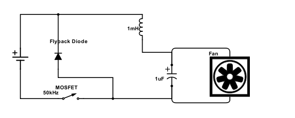
Of course power-source, MOSFET and flyback diode are already on the board and I would have to add the right half of the diagram. Right?
-
Yes, that's correct.
-
@dc42 Yesterday I connected the tacho output of the fan to my Duet. Although this fan is obviously not a 4-wire PWM fan it gives me quite stable RPM readings when I set my fan to a specific speed.
You said it might be that still this would give me bogus values and I found something really strange so maybe you could tell me if that could fall under what you warned me about:
My fan according to its specs (TFD-B5015M12B) has a top speed of 4500 RPM@12V. If I run it with
M106 S1it will get fullVinwhich in my case is 13.6V so of course it will run faster. But tacho readings tell me it runs at 6500 RPM. If I then run it withM106 S0.88it should get very close to 12V and the tacho reads 5500 RPM. Interestingly there is another model of the same family that would have exactly this speed @12V but I checked my order as well as the type label on my fan to not be the faster model.Of course there is a chance that my fan is labelled wrong or that they have changed the specs since this specific fan was produced. But I just wonder would it be possible for the RPM reading to be off at around 1000 RPM and scale according to this?
Manuel
Duet 3 6HC (v0.6) with RPi 4B on a custom Cartesian
with probably always latest firmware/DWC (incl. betas or self-compiled)
My Tool Collection -
@wilriker so this could be the H type with 5500. If you measure the current also, and it is 0.18 A instead of 0.14, then you have the other type.
-
@joergs5 To measure the current I would have to put my multimeter in series, right? Never done that so far.
Manuel
Duet 3 6HC (v0.6) with RPi 4B on a custom Cartesian
with probably always latest firmware/DWC (incl. betas or self-compiled)
My Tool Collection -
@wilriker directly into one of the main lines of the blower. Disconnecting the line and putting the current meter at those two open contacts. Be aware to set the maximum measure value of the current meter high first (above the maximum ampere, e. g. 1 A).
If it's a Molex connection, you can turn current off, draw out one of the cables (the pin have a barb, by pressing down you can remove the cable), connect to amperemeter at both sides, turn on and then measure.
-
@joergs5 OK, thanks for confirming. As I already cut my wires to the fan I think I can quite easily insert the multimeter in this circuit using some screw terminals... I need to put ferrules on the wire ends anyway, so that's up next.
Then again it would be really strange to have the
Htype when buying theMtype that is also labelled as being theMtype (including the amperage). I would expect this on a super-cheapo Chinese fan but not from a brand. But let's wait and see.
Manuel
Duet 3 6HC (v0.6) with RPi 4B on a custom Cartesian
with probably always latest firmware/DWC (incl. betas or self-compiled)
My Tool Collection -
@wilriker maybe labeled by someone who needs better glasses, M and H are similar
")
I thought it may be the H type because your 5500 measuring fits exactly to this higher model.
-
@joergs5 I know it would fit perfectly. Also about 6500 RPM @13.6V would match that quite well.
-
@phaedrux said in RC Low-Pass Filter for Blower Fan:
I was reading through this thread and was hoping someone could clarify the value of the inductor in the diagram above? I'm familiar with 1uH (micro-Henry) and 1nH (nano-Henry), but what does 1mH stand for? mili-Henry (1000uH)? for such a small amount of current?
-
@snowcrash said in RC Low-Pass Filter for Blower Fan:
I was reading through this thread and was hoping someone could clarify the value of the inductor in the diagram above? I'm familiar with 1uH (micro-Henry) and 1nH (nano-Henry), but what does 1mH stand for? mili-Henry (1000uH)? for such a small amount of current?
Yes, mH is milli-Henry.
Manuel
Duet 3 6HC (v0.6) with RPi 4B on a custom Cartesian
with probably always latest firmware/DWC (incl. betas or self-compiled)
My Tool Collection -
Thanks @wilriker!
But that's HUGE just for a fan that draws maybe 0.15mA, no? (ok, the fan will draw more current at startup but still...). Is there some calculation behind this value?
-
@snowcrash Actually I have no clue about all this stuff. I just took those numbers for granted (even though I would also like to learn about where they come from).
But just as an update: I dropped all this anyway since connecting the signal line showed that the fan actually turns at the speed I set it to, it just feels/sounds a lot lower - but then my ears and fingers are probably the worst way of measuring fan speed in the first place.
Manuel
Duet 3 6HC (v0.6) with RPi 4B on a custom Cartesian
with probably always latest firmware/DWC (incl. betas or self-compiled)
My Tool Collection