BLTouch V3.0 Information, Setup, and O'Scope Pictures
-
Hello!
I'm in the process of building my first custom printer and chose the Duet Maestro as my motherboard. So far, I love it! I also decided to implement bed-leveling and went with the BLTouch. Upon receiving my sensor from Amazon, I noticed it was the new V3, which had no information or manual at the time. I requested a manual from AntClabs, which they posted here for us. Due to unclear terms and my poor electronics knowledge though, I mostly installed it by trial and error, so I'm writing this post to tell how I installed my V3 and also include some pictures from my O'Scope of it's signal timing.
First, the basic procedure for wiring the V3 is similar to older versions. You can learn how in the wiki here. After following these instructions, it worked perfectly the first try. (without smoke!) I simply ignored cutting the trace for 3V because mine didn't have one.

I've noticed a lot of confusion on this new version, and was still curious about the "Logic-free Mode," so I decided to investigate!
As a full disclaimer, this is my first experience with a BLTouch, and is based on my experience only. I am not liable for burnt boards!

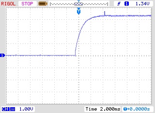
Using G30 to probe the bed, I got the following results at the output pin on the BLTouch when it triggered. This is still in the default mode. ("Logic Voltage Free ZMin" according to the manual)
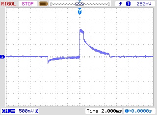
As you can see, the signal peaks at just over 1V, which should be safe for the Duet.Next, I sent a "M280 P64 S140" to put the sensor into "5V Logic ZMin" mode. Here are the results when probing again.
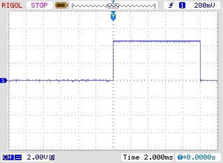
This gives a nice pulse near 4.5V, which is designed for compatibility with 5V electronics. The signal to put it in 5V mode has to be sent every time the sensor is power cycled. (It doesn't seem to "remember" it)I also did some testing in "Touch Switch" Mode (M280 P64 S60) and this brought similar results. Here's "Logic Free" mode (default)
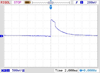
And "5V Logic Zmin" below (activated with the "M280 P64 S140 command)
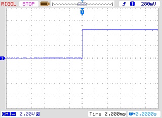
All of these tests were done with the BLTouch powered with the 5V, GND, and the MOD pins from the Z-probe pins on the Maestro.
Hopefully this helps someone! My experience has been fairly smooth, and I now love my BLTouch! Feel free to ask any questions you might have, and I can supply pictures of the V3.0 if somebody needs them.
Thanks for all the valuable information and time thats given here, and I hope this can help give some of it back!
--
@dc42 It would be great if you could verify my statements about the Maestro in this post. Thanks!
-
@JadonM, thanks for doing these tests and publishing the results. Based on your results, I recommend using the 5V logic Zmin mode because it provides the cleanest signal. The Z probe input on the Duet Maestro (and on Duet WiFi/Ethernet rev 1.04) can tolerate up to 30V.
@jadonm said in BLTouch V3.0 Information, Setup, and O'Scope Pictures:
@dc42 It would be great if you could verify my statements about the Maestro in this post. Thanks!
The only statements about the Duet Maestro I found in your post were this one:
the signal peaks at just over 1V, which should be safe for the Duet.
which I can confirm, and this one:
So far, I love it!
which only you can verify.

Duet WiFi hardware designer and firmware engineer
Please do not ask me for Duet support via PM or email, use the forum
http://www.escher3d.com, https://miscsolutions.wordpress.com -
@dc42 said in BLTouch V3.0 Information, Setup, and O'Scope Pictures:
I recommend using the 5V logic Zmin mode because it provides the cleanest signal. The Z probe input on the Duet Maestro (and on Duet WiFi/Ethernet rev 1.04) can tolerate up to 30V.
Would the 5V Logic Zmin mode also be best for Duet boards older than v1.04?
-
@phaedrux said in BLTouch V3.0 Information, Setup, and O'Scope Pictures:
Would the 5V Logic Zmin mode also be best for Duet boards older than v1.04?
no board older than 1.04 can not tolerate 5v on the zmin.
-
@veti said in BLTouch V3.0 Information, Setup, and O'Scope Pictures:
no board older than 1.04 can not tolerate 5v on the zmin.
More precisely: we can't guarantee that older boards will tolerate 5V, because that relies on the ESD protection diode within the MCU to limit the voltage, and although this works the MCU on the Duet doesn't have a rating for pin injection current. At 5V input, the injection current would be about 120uA.
-
In logic free mode, the BLTOUCH have a open drain output, so you must add a pull-up resistor connected between the output and the 3.3V.
Try with a 4.7Ko or 10Ko.
See the latest manual : here
mode : 5V Logic Zmin (Never activate on 3.3V Logic)
mode : Logic voltage Free Zmin (default : open drain) -
@pipersw said in BLTouch V3.0 Information, Setup, and O'Scope Pictures:
Logic voltage Free Zmin
if the duet works best with 5v logic and the ramps boards also need 5v, what is the point of the new default?
-
The Duet is 3.3V input, but the input allow up to 30V for input because internal diodes clamp to 3.3V.
But it's more clean to output 3.3V signal from the BLtouch I think, because it's the native voltage.
Just add a pull-up resistor to 3.3V. -
The first waveform seems to have ac coupling. I presume that the oscilloscope was set to DC coupling.
https://forum.duet3d.com/assets/uploads/files/1554913522808-homing-logic-free.jpg
-
@zapta said in BLTouch V3.0 Information, Setup, and O'Scope Pictures:
The first waveform seems to have ac coupling. I presume that the oscilloscope was set to DC coupling.
All the measurements were done with DC coupling. I'm thinking the weird waveform might be the result of no pull-up resistor, as referred to by @pipersw.
I've done some more measurements, this time with the BLTouch's output connected to the board and o'scope. Before I had it connected to the o'scope alone. This yielded much different results. Does the Duet Maestro have a built-in pull-up resistor?
Above is with the output connected to the board in "Logic Free" mode. This waveform looks much more sensible and is at around 3V, not the previous 1V when it was unconnected.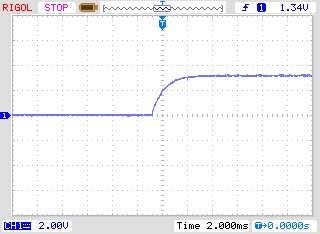
This is with the BLTouch in the 5V Logic Mode, but to my suprise, it seems to only show about 3V. Is that because of the clamping diodes, @pipersw? -
@jadonm said in BLTouch V3.0 Information, Setup, and O'Scope Pictures:
Does the Duet Maestro have a built-in pull-up resistor?
Not an expert, but it may be this: https://i.imgur.com/jPdCPKm.png
From second page of this PDF https://github.com/T3P3/Duet/blob/master/Duet2/Duet2Maestro_v1.0/Duet2Maestro_Schematic_v1.0.pdf
-
The Z probe input of the Maestro has an internal pull up resistor inside the microcontroller, value about 100K. I am fairly sure that it is enabled when you select BLTouch probe mode, but I will check.
Duet WiFi hardware designer and firmware engineer
Please do not ask me for Duet support via PM or email, use the forum
http://www.escher3d.com, https://miscsolutions.wordpress.com -
@jadonm Yes, it's the clamping diode whose stuck at 3.3V.
-
@dc42 said in BLTouch V3.0 Information, Setup, and O'Scope Pictures:
The Z probe input of the Maestro has an internal pull up resistor inside the microcontroller, value about 100K. I am fairly sure that it is enabled when you select BLTouch probe mode, but I will check.
On schematic of Maestro, there is a external 10k pull-up, so the internal pull-up of the processor is don't care if enabled or not, because it's around 10k in all case.
-
@pipersw said in BLTouch V3.0 Information, Setup, and O'Scope Pictures:
On schematic of Maestro, there is a external 10k pull-up, so the internal pull-up of the processor is don't care if enabled or not, because it's around 10k in all case.
If you mean R62, that's a 10K series resistor, not a pullup resistor.
I have confirmed that the internal pullup resistor is enabled when BLTouch mode is selected.
Duet WiFi hardware designer and firmware engineer
Please do not ask me for Duet support via PM or email, use the forum
http://www.escher3d.com, https://miscsolutions.wordpress.com -
@dc42 No, if I take the picture
 , I mean R70.
 -
That's the Z endstop connector, not the Z probe connector.
-
you are right !
-
I have a V3 bltouch installed as per setup guide for the Maestro. When I turn on the board to BL blinks with an error, I have to turn the board off and on several times before it will do a self test. No resistor is used.
-
@cabal2000, was the bed too close to the nozzle when you turn it on? If the BLT doesn't have sufficient mechanical clearance on power up, it enters an error state and blinks. I added to my homeall script a BLT error reset command I found in one of the threads here.
M280 P3 S160 I1