Best way to manage vertical forces on lead screw
-
Hi guys , I am planning to change my D-Bot Corexy Z axis setup. My bed is quite heavy ( 330x330x8 aluminum ) and I would like to manage better the vertical forces applied on the lower ball bearing adding a thrust bearing.
This is what I am thinking about.
I have another question .
I saw people fixing the lead screw both on lower and higher part of the frame with 2 KP08, and in the middle a T8 screw attached to the bed structure. It seems to me an overconstrained structure and I am thinking about using only 2 fixture point bed and lower frame.Thank you for your time.
Andrea -
IMHO Your idea is the way to go and is indeed the way I am doing my build although I will be using Oldham Couplings rather than a rigid one.
Doug
-
@dougal1957 said in Best way to manage with vertical forces on lead screw:
Oldham Couplings
I was thinking about a rigid one because I am thinking about using an Oldham on the bed side https://www.thingiverse.com/thing:2858698 , and because the KP08 has some auto - centering capabilities, but I can change my mind easily
")
Something like this? https://bit.ly/2IYHm9LI am also thinking about leaving the Jbot mod , with bed mounted on 4 corners and return to cantilevered one , this time will be supported by the third screw on the front and this should be more then enough .
Another option I am thinking about is trash the 3 screw idea , go cantilevered with 16 mm road and single motor on the back something like this https://www.thingiverse.com/thing:2094263
I really need a concrete input because more then I think and more I lose the way
-
I will be using oldham on the motor fixed nut on the bed 2 Linear rails 3 screws with independent motors for levelling and the top end of the screws totally unconstrained (my screws are 600mm long and my bed is 450x450 x 6 Cast tool plate).
-
@claustro The belt driven Z in the machine you linked came from here: https://www.thingiverse.com/thing:3427719
If you read through the description, he has a problem with print quality because of the quality of the worm and disc gear, which matches my own experience with a different cheap set of gears from China. Any error in the worm gear repeats in the Z axis each time the worm gear rotates.
The Rino worm drive I used is fine- quality motor, gears, bearings, aligned perfectly, in a sealed housing. You can't build the equivalent by buying parts at a lower cost. Quality gears are very expensive.
I'd avoid cantilevering the bed, especially if you're using end-supported round guide rails in the Z axis. The cantilever is like a long lever arm trying to flex those rails, (and the printer's frame that they attach to) and it will succeed. You'll have to limit print speed to minimize the bounce.
-
I have a CoreXY with 2 Z screws and 2 16mm Z rods all inline. The rods are just outside the Z screws on the left and right side through the middle of the bed. The bed is obviously balanced with centre aligned rods and screws, with quite "large" T printed parts holding the bed and each with 2 linear bearings about 100 centre-centre on each rod. Very rigid, smooth operation, straightforward to assemble and align.
The screws are T8 single start 2mm pitch and 2mm lead with a stepper motor on each screw. (My bed is not heavy so no vertical thrust issues). The 2mm lead is a benefit to most printers I suspect, more so for your bed weight. They are unsupported at the top and remain vertical because the T nut is about 120 minimum above the lower coupling at max Z. They wobble slightly under high Z speed in the infrequent periods when the bed is at max (lowest) Z, but not excessively.
I have also a belt that keeps the screws synchronised for power off. The belt was delicately tensioned via an idler wheel and its drive pulleys aligned with the motors on full amps with no microstepping enabled. Although the motor purists may disapprove, it works well. A single motor is obviously an alternative especially for your thrust bearing needs.
I caution you about cantilevering your bed unless you get very serious about bed mounts, and if you use a 3rd screw in the front that will be inconvenient.
I don't understand the need for more than 2 screws or rods except in very large format printers and 330 x 330 is not very large. 16mm rods may be excessive from one engineering perspective but from another engineering perspective they are perfect. Operate well, no disadvantages, certainly rigid, added mass to the frame and not even a noticeable cost penalty. My Core XY has hollow 10mm X rods 12mm Y rods and 16mm Z rods.
Today was a big day as my 2 Core XY printers were both functionally complete today after a long process, although some aesthetic improvements will occasionally be added in time.
-
@Garis thank you for sharing you experience , I am not a native english speaker ( obviously
) can you share some photos of you solution? If I undestand correctly your bed is sustained only in 2 points at 3 and 9 o'clock is it right?@mrehorstdmd Yes I saw the problem of belt dirved Z axis , I almost learned all your blog's pages and I am not willing to follow the belt path to much complicated for my ability and my needs, I was referring to the Z 16 mm road mod so in your opinion ,a 4 corner constrained bed is the best solution?
If I understand correctly with this setup a 3 motors autolevelling option isn't doable .
Maybe permitting to a bed structure to move, even a little , to make the bed planare need a structure tha leave at the screws not only the movement duty but also the stability one so no the best solution .
Is it correctThe willing to mod my printer is driven but the feeling of not having a rock solid Z axis.
I am going to mod the bed following mrehorstdmd so this is the perfect timing to change something if needed. https://forum.duet3d.com/topic/10165/new-three-regulation-point-aluminium-bed/2
-
Here is a link to my blog which shows how I did mine https://somei3deas.wordpress.com/my-corexy-printer-build/ The first picture shows bearing block for the 3 Z axis screws. Basically it's a blind hole with this type of thrust bearing in the bottom which takes the downward forces of the screw https://alexnld.com/product/machifit-5pcs-flat-thrust-ball-bearing-id-2-5-3-4-6-7-8mm-mini-miniature-bearings-f25-6-f3-8-f4-10/?gclid=CjwKCAjw-4_mBRBuEiwA5xnFIMmuFWOdWh1tSZ58Hd42pMR8CAf5EhcorzMjnnxStq7UCE0lsS8GqhoC7lAQAvD_BwE .
The screws are unconstrained because their job is to lift the bed, not guide it - linear guides do the guiding, the screws do the lifting.
-
@claustro No, I would not use 4 points to guide or lift the bed. Two screws, located close to two guide rails, and a third screw to lift/support the opposite side/end of the bed will be stable and won't bounce.
-
@mrehorstdmd yes when I was talking about 4 points I meant 4 linear guides ( linear bearing vslot ecc..) and only 3 lifting screw.
@deckingman your and mrehorstdmd printer are really monster printers
If I understand correctly looking you blog and your tube video at least on the older setup you was using a no cantilevered bed guided by 4 V-slot carriage with with 3 wheels each and 3 thread.
Your Z rod thrust and ball bearings seems quite clever and simple but can I ask you how the threaded road retained in place?even talking in not my native language and through a forum is helping me a lot , and little by little I clarifying my ideas, I need to say thank you at all of you for be so patient with me .
-
@claustro I have taken some photos, will edit them and post tomorrow (Australian time).
Rods and screws at 3 and 9 o'clock and T brackets keep the bed frame (2020 tubing) horizontal. The bed itself is 4mm glass suspend on 3 levelling points (12 4 and 8 o'clock) on the bed frame. 3 is a good number - even the X carriage runs on 3 short linear bearings, 2 on the lower X rod and 1 on the top rod in self aligning slots. The idea is all the mechanicals provide the accuracy. The rods and bearings arranged so no binding on the rods, and with no need for XYZ corrections or bed levelling or Z probes but the bed is only 250 x 250. -
@garis thank you I can't wait to see your work!
-
@claustro There's no need to use 4 guides for the bed. Two is sufficient to constrain lateral motion. Adding more does not increase stability and can cause problems. It can be difficult to get two guide rails parallel to each other. Aligning 3 or 4 guide rails is a much bigger problem.
-
@claustro said in Best way to manage vertical forces on lead screw:
@deckingman your and mrehorstdmd printer are really monster printers
If I understand correctly looking you blog and your tube video at least on the older setup you was using a no cantilevered bed guided by 4 V-slot carriage with with 3 wheels each and 3 thread.
Your Z rod thrust and ball bearings seems quite clever and simple but can I ask you how the threaded road retained in place?No that's not correct. I use 3 screws to lift the bed but only two V slot linear guides. Each guide carriage actually has 4 wheels, 2 per side but they could have been made using 3 wheels (2 wheels on 1 side and 1 wheel on the opposite side).
The (trapezoidal) threaded rods just sit in the bearing blocks with the ends resting on the thrust bearings. Gravity keeps it them place - the weight of the bed means that it can't rise up. The flanged bearings fitted above the thrust bearings prevent any side to side movement. The lead screw nuts have a compressible O ring where they fix to the bed mount and a ball type rod end is used to connect to the linear guide carriages. This allows some degree of flexibility for the initial bed levelling. The 3 screws are driven by a single motor via a continuous belt. Bed levelling is accomplished by slackening the grub screws on the pulleys and rotating the lead screws by hand. I don't use any other form of levelling or flatness compensation and I only need to level the bed if the machine is taken apart and transported to another location.
-
@deckingman said in Best way to manage vertical forces on lead screw:
No that's not correct. I use 3 screws to lift the bed but only two V slot linear guides. Each guide carriage actually has 4 wheels, 2 per side but they could have been made using 3 wheels (2 wheels on 1 side and 1 wheel on the opposite side).
The (trapezoidal) threaded rods just sit in the bearing blocks with the ends resting on the thrust bearings. Gravity keeps it them place - the weight of the bed means that it can't rise up. The flanged bearings fitted above the thrust bearings prevent any side to side movement. The lead screw nuts have a compressible O ring where they fix to the bed mount and a ball type rod end is used to connect to the linear guide carriages. This allows some degree of flexibility for the initial bed levelling. The 3 screws are driven by a single motor via a continuous belt.
I can't fully understand your setup it isn't cantilevered right? , I am studying your video but maybe I am not to smart enough to understand ..


-
@claustro Those two VSlot sections are linear guides which prevent the bed from moving in the X or Y directions. They have nothing to do with supporting the bed. There are 3 lead screws that support and lift the bed. One is located in the front left corner, the second is located in the front right corner, and the third is in the centre at the rear. Those 3 screws therefore form an triangle and as 3 points define a plane, then turning the 3 screws simultaneously lifts the bed evenly.
-
@claustro I have posted details and photos at "My Hypercube Evolution CoreXY variant" in the category "My Duet controlled machine."
https://forum.duet3d.com/topic/10270/my-hypercube-evolution-corexy-variant
-
@deckingman excuse me but maybe my poor language propriety prevent me to express clear concepts.
I clearly understand that you have 3 screw in a triangle disposition
From your video and from what I believe to understand your printer has only 2 guides positioned in diagonal respect of the bed and If correct this is the first time I see such disposition.
Your printer is AWESOME, my congratulation for the results achieved.
@garis thank you for posting images, very beautifull printer , it seems sturdy with many aluminium component have you noticed improved shifting the z roads in the middle? at what speed is able to print with good quality?
Andrea
-
@claustro Originally the two linear guides were both at the front of the bed. But I discovered that if I gripped the bed with 2 hands, I could rotate it in the XY plane. The reason was that the guides were 2020, fixed to the frame with a single bolt top and bottom. This arrangement meant that the guides could "flex" around that single fixing. So I could have either replaced the 2020 with 2040 and used 2 bolts side by side, or move one of the guides to the rear. The quickest, cheapest and easiest option was the latter. In reality, it might never have been a problem because there wouldn't normally have been any rotational twisting force applied to the bed. But it was a potential problem and easily fixed so that's why the guides are placed as they are. Hope this translates well into your native language.
-
@deckingman thank you for taking time of answering me, very cleaver solution
I am afraid of solution with only 2 guides on one side , it seems impossible to me totally eliminate the tendency to bend for the gravity. Have you ever had this problem in the previous configuration? Your solution seems to solve both problems: XY rotation and Z flexI was thinking about the thrust and ball bearing setup.
I can't understand how the thrust bearing work in your setup.I never had a thrust bearing in hand so excuse me if I am wrong.
If a thrust bearing behave like a regular 608zz bearing an 8mm lead screw can easily pass trough it.
This lead at two phenomena- The lead screw can can make friction to underlying plastic support.
- There isn't vertical force to dissipate 'cos nothing rest over the thrust bearing
My statement above decade if the lead screw fit perfectly in the trust bearing without passing trough it.
I usually saw trust bearing and lead screw mounted with collars or other type of vertical stop .
I am confused
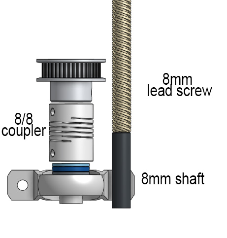
@Dougal1957 If you are planning to use a flexible coupler , that seems reasonable , are you planning to use a shaft for letting the coupler to flex?