Indirect (bearing) laser filament monitor concept
-
@Adrian52 said in Indirect (bearing) laser filament monitor concept:
@dc42 Excellent advice. I have connected to stop 10 on conn_lcd using shielded cable (a repurposed USB cable that also has a ferrite ring), and the errors are now zero. I have got up to 3mm/second filament (0.5 width, 0.3 height at 60mm/sec) and the max/min were 107%/95% of the average. Wow.
@Adrian52 , Are you saying that by using the direct filament (stock so to speak) enclosure you are getting zero errors now that you have a shielded cable running from your sensor to the board? I am debating on attempting your indirect enclosure concept but if you had success by making a wiring modification perhaps that is a better way to fix this.
Also, Any chance you would want to factor in a roller micro switch into your mod so that the sensor can be used as a static filament present sensor as well?
-
This is a really good design. Have you built one and tested it yet? Thanks
-
I am attempting to print the enclosure for it now. I could prob build a few because I will have a few left over parts. Parts are still on order. I am curious if a carbon tube would work instead of the rod. The design seems to show some notches cut so I went with the solid rod.
-
@mitch sorry for the late reply - been away. I have an early duet wifi, which apparently doesn't have optimal filtering capacitors on endstop inputs for the filament monitor. I have had no errors at all since using a conn_lcd input with a shielded cable.
I have not tried a static switch - I only have one printer, so the runout function of the monitor is fine for me.
I have found the indirect monitor arrangement excellent- the monitored total extrusion is usually spookily accurate. -
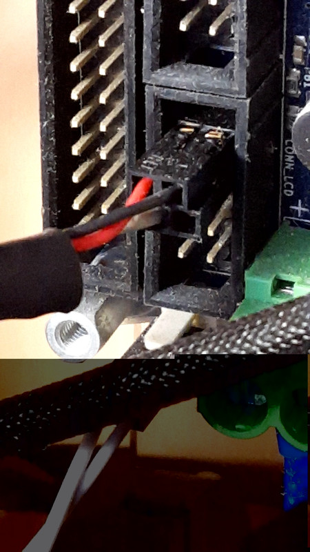
@Adrian52 When you connect to the laser to the CONN_LCD header I assume you are using pins 9 (STP 10), Pin 1 (+3.3V) and Pin 2 (GND). Is that correct? If not can you be more specific on how you connected or better yet provide a picture? Thanks
-
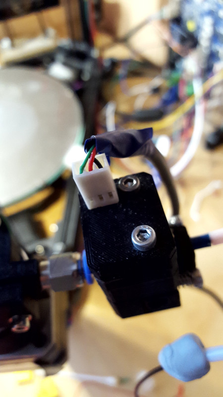
@JADoglio Here is how I am connected to the conn_lcd input:
 , with the connection at the monitor:
This is the snippet from config.g:
;****rrf2******
;M591 D0 P5 C10 R200:400 E10 S0 A1		;extruder 0, laser w/o switch, e0 endstop, 40-160% range, 10mm, inactive (S1 active), check all motion
;****rrf3******
M591 D0 P5 C"connlcd.encb" R40:360 E10 S0 A1	;version for reprap3
As you can see I currently use the rrf3 version. Hope this helps.
-
@Adrian52 It helps very much. Thanks
-
@Adrian52 One other question. I have not found a good explanation for when to use the "S" parameter. When it is active does that mean the sensor will detect jams in addition to run outs? I assume when it is inactive it will still detect runouts. Any clarification on this parameter would be helpful. I am also not using the "A" parameter. Should I add that as well and what is its function. Thanks again.
-
@JADoglio my understanding is that with S1, the monitor pauses the print if the extrusion falls outside the specified range. So it will pause on blockages if the extrusion is sufficiently affected. I didn't think you got a pause with S0, even with runout - not sure if this applies with a microswitch added. I have only used A1 so far - will investigate A0 sometime. You do get a pause with S0 if you have a wiring fault - I had some irritating pauses until I fixed a dodgy crimp.
-
@Adrian52 Thanks. You are right even on run out when S is set to 0 it will not stop the extruder. I did that experiment a few days ago and just forgot about it.
-
@Adrian52 what does the A parameter do? I don't see that defined on the reprap g-code wiki site.
-
@mitch see https://duet3d.dozuki.com/Wiki/Gcode#Section_M591_Configure_filament_sensing
An (firmware 2.03 and later) 1 = check All extruder motion, 0 (default) = only check extruder motion of printing moves (moves with both movement and forward extrusion)
Ian
Bed-slinger - Mini5+ WiFi/1LC | RRP Fisher v1 - D2 WiFi | Polargraph - D2 WiFi | TronXY X5S - 6HC/Roto | CNC router - 6HC | Tractus3D T1250 - D2 Eth
-
@droftarts Thanks
-
I'm waking up this topic, ( deleted mine also ).
Here is my version of indirect filament reading, inspired by your ideas here.
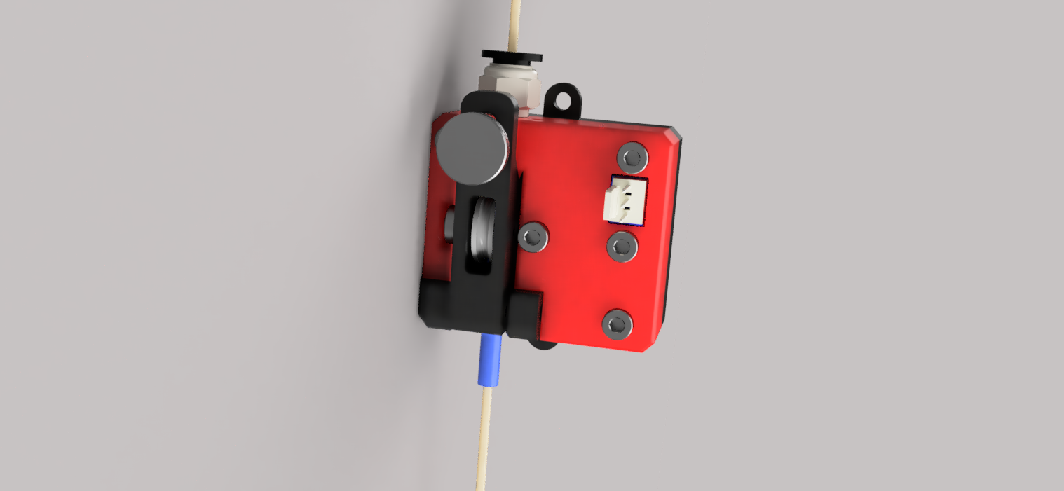
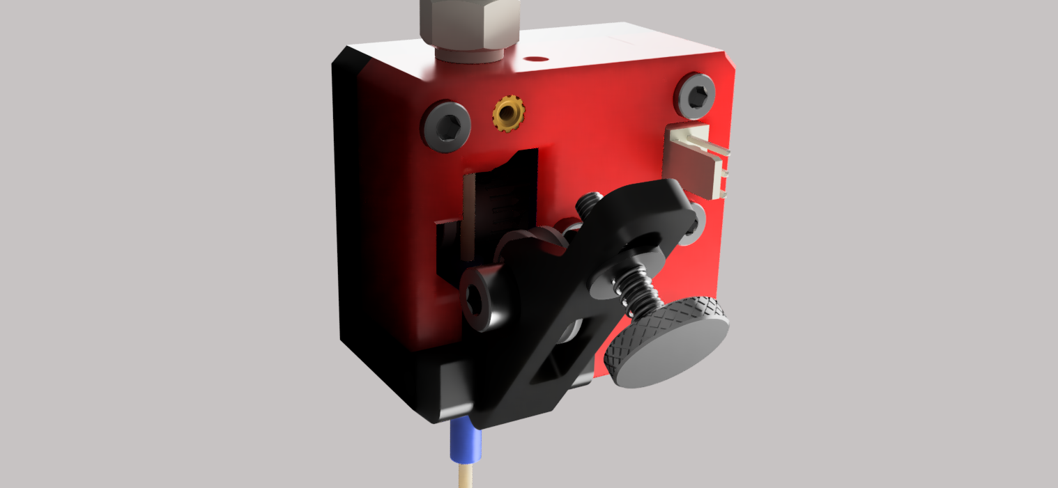
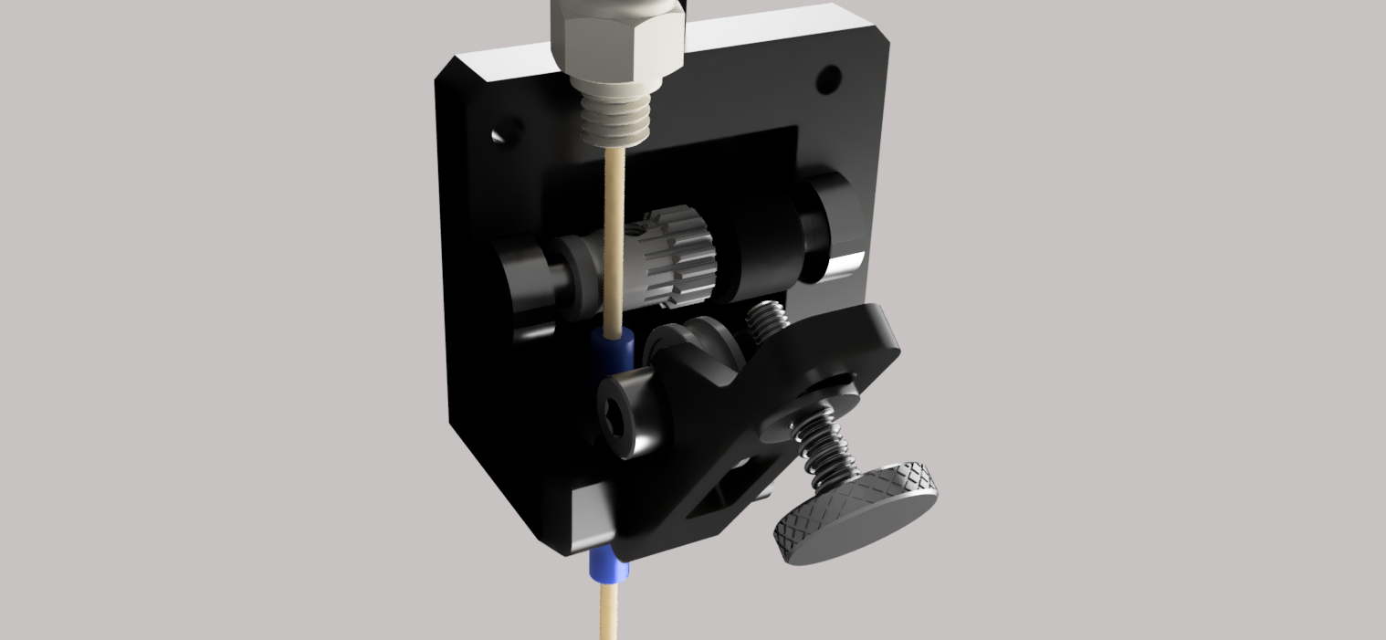
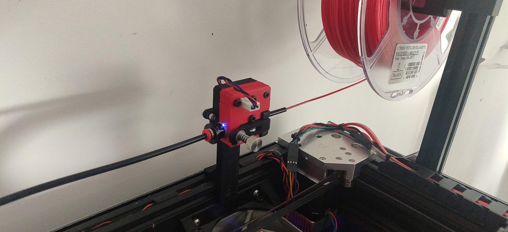
It uses an 5mm shaft hobbed gear from Bondtech and U shape bearing on the latch.
Tensionning can be adjusted from the latch.I use it outside of my DD carriage, don't have any problem with retractions ( considering I have 0.6mm retracts this prollyt explains why ).
https://www.thingiverse.com/thing:4882602
I get readings from 188% to 266% , average 230%. Is it acceptable or should I try to read around the 100% ? I think I can tweak it by adjusting the printed wheel diameter.
-
@kipk you can adjust the calibration factor in RRF 3.2 and later using the M591 L parameter. See https://duet3d.dozuki.com/Wiki/Gcode#Section_M591_RepRapFirmware_Num_3.
Duet WiFi hardware designer and firmware engineer
Please do not ask me for Duet support via PM or email, use the forum
http://www.escher3d.com, https://miscsolutions.wordpress.com -
@dc42 ho that's just perfect then.
-
@brunofporto just use a bondtech hobbed gear - that's what I use and it always engages with the filament to register movement.
-
That's what I use here, bondtech hobbed gear.
So after using the calibration factor + few change on the indirect casing, I now have this reported values :
measured min 93% avg 101% max 107% over 12365.3mm
Looks far better than what I ever achieved with direct reading.
I still have some false trigger because of the PTFE tube moving too fast with high acceleration, I will restrain it before the filament reader. -
 undefined droftarts referenced this topic