Black Beauty Arises!
-
@mrehorstdmd That's a good idea.
 The bottom frame sits up on hefty appliance rubber blocks. I could mount one on the inside of the front bottom member that you'd have to reach under to get to. And if you didn't stick your fingers in the exact correct place... ZAP!
 -
Z Axis:
Build Plate

The build plate is 510x510x6mm aluminum tool plate which was pretty flat to begin with but touched up by me. It used to have a full-surface Printbite sheet on it but after a year, the adhesive started to pull away so I stripped it off and put some pieces of PET down in the critical printable areas. I need to find an alternative for full surface coverage again.
The 3 screws are Tr8*8-2p (4 starts) x 540mm.

Bed Mount Assembly (back)

The nuts are Delrin with an anti-backlash extension. Don't really need the anti-backlash but they keep just enough tension on the screws to keep the bed from falling when the motors are off.
On the bottom of the build plate you can see the 500x500 Keenovo 1600 watt heater (overkill but the only wattage I could find in 500x500) and the bed mount. There's a 10mm ball end screwed into the extrusion that a nylon block with a slot in it fits on top of. The slot is angled to point to the center rear mount which has only a round hole to match the ball end. The bed can expand and contract towards the front corners but not twist. You can also see the home-made multi-layer insulation pad. It's composed of interleaved layers of mylar and fiberglass cloth. Keeps the heat in nicely.
Z Motor Assembly

The bottom bracket holds the motor but neither that bracket nor the motor carry the vertical axial load. The top bracket is also a standard NEMA 17 bracket that happens to hold a F608ZZ 8x22x7 flanged bearing perfectly. The shaft coupler has a slight gap in it so the force is taken by the clamp collar and transferred to the bearing core, the bearing housing, the upper bracket, to the frame. The bearing isn't really rated for axial load but there's not enough weight on them to matter. Besides, they're dirt cheap and can be replaced easily.
Bed Mount Assembly (front)

The linear rails are Igus N series 17mm wide rails. You can see the beige bearing sitting in the rail.
The actual L bracket is printed with Proto-Pasta Carbon Fiber High Temp PLA which has been heat treated.That's it for the Z axis. XY coming up.
-
XY Kinematics
Monoplanar CoreXY

Tool Carriage

Kinda hard to see being black on black, but that's a Zesty Nimble on a custom printed mount. The black hoses provide hotend and part cooling air. You can also see the Precision Piezo Orion tucked in there.Tool Carriage (Lower)
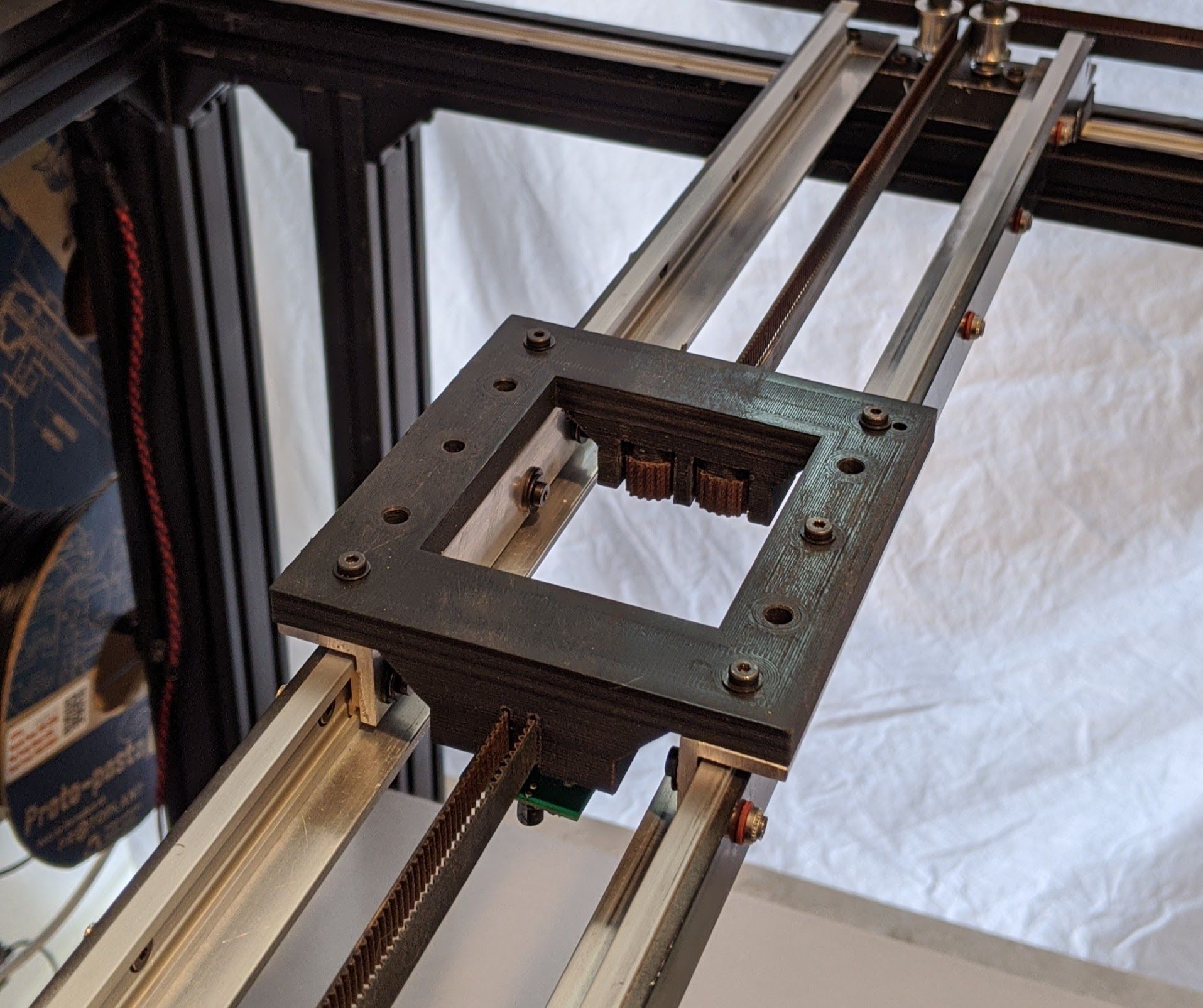
It's actually 3 pieces. 2 aluminum 90deg angles that have the 2 Igus carriages bolted to each plus the printed mounting pate that has the X endstop and belts mounted to it.Upper Mounting Plate

You can see the Nimble and Orion much clearer now. The hot end is an E3D Volcano and you can see where the cooling air tubes connect to the E3D shroud on the left and the part cooling nozzle on the right. Again, the printed parts are all heat treated high temp carbon fiber PLA. Now that I'm pretty confident in the design, I may replace the printed parts with an all aluminum mount. Although I've had no issues with the printed parts, they are a little bulky.X Axis View

You can see the 2 Igus rails sitting in more 90deg aluminum angle pieces. The combination of the rail plus the angle form a very rigid truss. Looks a little dusty in there.
Right Carriage

More Igus rails and carriages. The two idlers sit on M5 bolts with shims to make sure the idlers themselves don't touch the bolts or mount and can rotate freely. Those are genuine Gates 9mm belts by the way. Actually it's one long belt because I don't trust myself to make multiple cuts.
Right Idler Assembly

It's just a hefty chunk of aluminum "T". Notice that one of the idlers is smooth and the other is toothed to match the orientation of the belts. The inner idler is perfectly aligned with the 2 idlers on the carriage and the drive gear on the stepper.Right Stepper

Stepper, drive gear, optical endstop and you can even see the bullet USB cam sticking out towards the right.Back Belt Separator

Every monoplanar corexy needs a belt twist somewhere. Since the span is over 600mm, twisting the belts imparts no unusual load or wear on the belts or idlers. I did need a separator to keep the toothed face of the belts from rubbing against each other though. It's just another chunk of aluminum angle that I polished to keep friction to a minumum. Ignore the stupid white sticker remnants. It was there to provide an alignment target and I forgot to get out the acetone to clean it off. -
Whew.
In the end I'm not sure exactly how many design generations I had. According to Fusion 360, some of the parts had over 150 revisions. In the end I wound up with a build volume of 460x450x460mm.
I never really talked about the choice of extrusions though. I chose the 25 series (25x25, 25x50, 50x50) because the other series were either too expensive or not strong enough. It also happens that the 50x50 I use in the posts and bottom rails are so close to 2 inches that standard NEMA 17 motor mount width matches almost exactly. The down side is that the mounting slots on those brackets are 30mm apart, not 25. I had to do some surgery on the two XY motor brackets to get them mounted. It was ugly.
I'm still trying to calculate how much it would cost to build this design without any of the intermediates. The extrusions alone were about $480 but they were cut perfectly and I had to do no tweaking. The Igus rails were about $40 each and there are 7 of them so about $280. The Igus carriages were between $3 and $5 each and there are 11.
As for time, if I had to guess, it would take me a full day to build and true the exoskeleton, the same for the kinematics, and another two days to do the wiring. This is of course with the lessons learned from the first time, mostly around the order of assembly. I also wound up making some jigs and gauge blocks for things like positioning of brackets, centering the Igus rails on the extrusions, etc.
Of course there are still some things I'd have done differently but I can't remember them now.

More on print quality, speeds, resolution, etc. coming.
-
Thanks for posting this! Very impressive and as others have said already, something to aspire to as far as wiring goes!
-
-
@sonderzug said in Black Beauty Arises!:
@gtj0 very nice machine! As you're calling it "black beauty", this is probably a bad time to tell you about black anodized igus drylin rails?
 How's your experience with the igus rails so far?
Best, Niklas
also @wilriker
Ha! The black anodized rails were either not offered yet or weren't stocked in the US when I placed my order over a year ago. I don't remember which. You can probably see from some of the pics that I attempted to black them out myself to varying degrees of (un)success. If I were starting over, I'd get the black anodized. They're about $6/meter more expensive but that doesn't add much to the overall cost.
I really like the rails and carriages.
Good:
- Being aluminum they're easy to trim and drill
- Easy to mount and support
- The bearing surfaces are self cleaning
- They're amazingly quiet
- They're light
Bad
- Being aluminum they scratch more easily. The bearing surfaces are pretty well protected though.
- The 17mm width rails need support over long distances. At one point, I did use the cross rails without
the aluminum angle supports and I could deflect the center downward with finger pressure. It was still strong enough to support the tool carriage without deflection and print quality wasn't affected but I added the angle stiffeners just in case. At one point I was also toying with the idea of using the 27mm versions for the cross rails and i may again. Definitely wouldn't need the stiffeners in this case. - You have to understand how the carriages fit into the rails and where the loads are. The carriages come in 3 different lengths and 4 different float options per length. You have to use the right carriage for the rail orientation. In Black Beauty's case, the Z axis rails are vertical, the Y axis rails are horizontal and flat, and the X axis rails are horizontal and on "edge" so it took some experimentation.
-
thanks for the write-up. I myself opted for drylin for my printer build, but got rid of them after all, because the system had some play when changing directions which lead to things like un-round holes etc... but I chose the wrong type which had no way of adjusting play in the bearings. How are your experiences with precision? Can you show some sample prints?
-
@sonderzug Yeah it's not a simple process to match rails, carriages and application and regardless of the technology, when you have parallel rails you have to deal with preloading, and alignment.
I just pulled off the green PET sheets from the bed last night and I have a large PEI sheet coming tomorrow so once it's applied I'll do some sample prints again.
-
@gtj0 Did you need to do anything to manage the clearance of those Igus slider parts? Is there enough to be perceptible on the prints? Also, is there any evidence of wear to date, in your use?
Thanks -
@Tony-Owens said in Black Beauty Arises!:
@gtj0 Did you need to do anything to manage the clearance of those Igus slider parts?
Yes. First, I used the "overmolded" version of the sliders. These have almost no play in any axis. Second, I created jigs to hold the left fixed "Y" rail so it was perfectly parallel to the support extrusion then once it was fastened and the gantry was assembled and squared, I used the gantry to fix the right rail in position placing just enough tension on the bearings so the gantry couldn't move in the "X" direction. It doesn't have to be enough tension to prevent racking because the CoreXY kinematics do a good job of preventing that anyway.
The gantry itself where the rails are "vertical" was a tougher challenge to align. So much so that after I took those pictures the week before last, I decided to re-orient those rails horizontally as well.

Is there enough to be perceptible on the prints?
None. My brother is a nuclear chemist (DNA, etc) and a few weeks before I started the rebuild he asked if I could design and print some special sample holders that lay on top of microscope slides, could hold a puddle of buffer solution, AND was dimensionally consistent so that they would fit into an analyzer they had developed. I printed a single batch of 50 out of TPU and sent them off and he said all 50 were perfect. No jams, no leaks.
I just went looking for the test cube I printed last week before I took the gantry apart to re-orient the rails but I think I threw it out. I should have everything back together again in a few days and I'll print another.
Also, is there any evidence of wear to date, in your use?
I'm using the same sliders I ordered 2 years ago. When mounted flat, the bearings actually have 4 slightly raised pads that contact the rails that make them self cleaning for the most part. Since anything that's going to generate dust is also plastic, a quick spray with some compressed air every week keeps the rails nice and clean. The rail bearing surfaces are fairly well protected but if you cut or drill the rails yourself, you have to make sure that you don't nick the bearing surface or deform the rail. You also have to file every cut smooth and clean every trace of aluminum dust and shavings before inserting the sliders.
BTW, every article you've ever read about designing and tuning parallel rail systems applies here as well. igus even has an article on their web site about it.
-
I think the susceptibility to jamming of parallel rail systems can be large overcome with minimal loss of stiffness by using parallel flexures in one of the linear rail truck mounts. But only in a system with parallel driving on both linear ways such as CoreXY or twin ballscrew.
I tend to use the simplest and cheapest of IGUS products if at all, due to their attitude to precision. I like them for damping, silence and no need for lube. While other tribopolymer bearing developers like PBC have addressed imprecision of extrusions and heavywall moulded plastic bearing parts in various ways, IGUS resolutely isn't interested in precision plastic bearings combined with reasonable value for money. I had them in to visit with me recently in connection with tower bearings for a heated chamber Delta printer I'm involved with. While they have a range of tribo bearing materials that are rated for service up to 180C, the hard anodised aluminium rails themselves are not suitable for service with these grades, and steel tubes or shafts are needed to exploit them and get a reasonable wear life. I think the material you chose for your sliders is probably a general purpose grade they call J. That is OK to about 80-90 C and works very well with hard anodise.
I'm impressed by the implied quality of printing you can get even on v small TPU parts. Perhaps one reason for that is the relatively stiff structure of your machine, and the structural damping and absence of stick-slip provided by the IGUS bearings?
-
Updated XY Gantry
I went ahead and went back to an arrangement where the rails are laid horizontally. It's much easier to tune and results in a simpler, lower mass design.
Here's the right-side carriage:
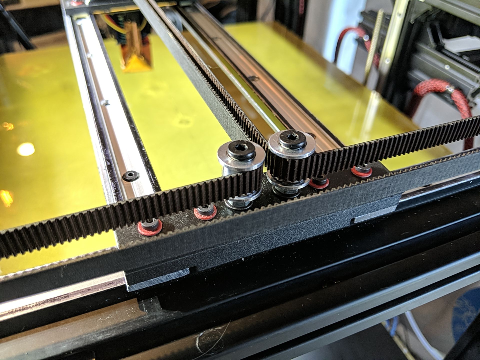
The pulleys are bolted to a piece of6(oops 3) mm aluminum which sits on top of a printed spacer. The 4 screws go through to the 30mm Igus sliders. The pulleys have to be offset from the carriage center line towards the inside by 0.375mm to make the belts co-linear and parallel. Since I'm lucky to get a tolerance of 3 mm with my cheap drill press and bad eyes, I printed templates then drilled through them to get the correct spacing.Left side:
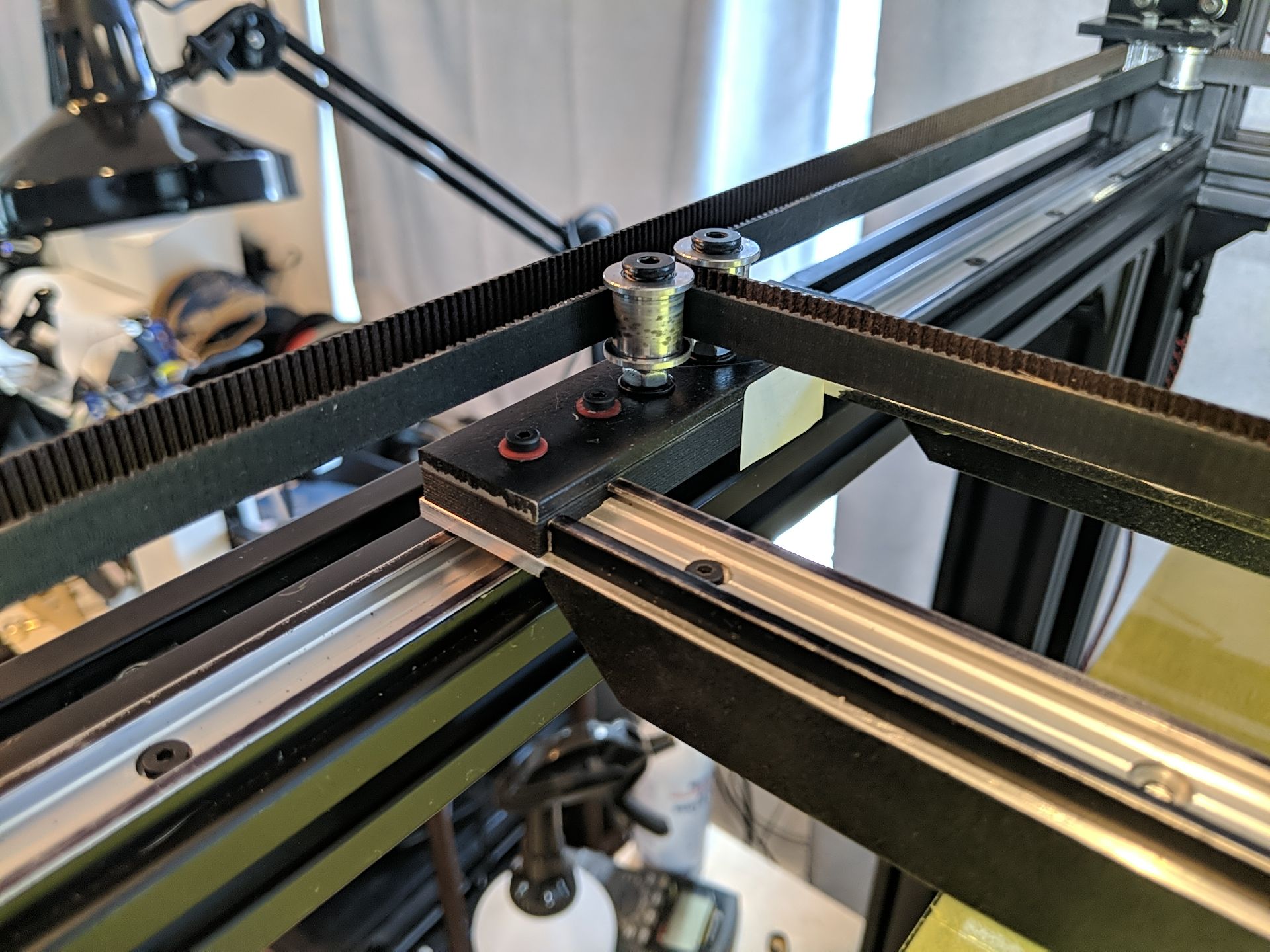
You can see the aluminum plate a little easier. The support truss extends all the way under the carriage.Center Carriage:
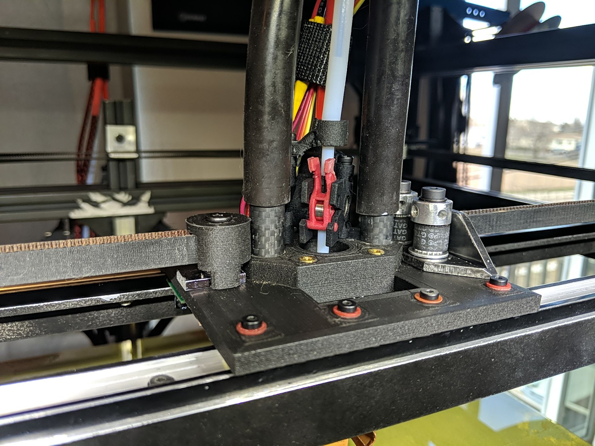
Now one piece instead of 4. As I said earlier, the belt is one long 4.68m piece. The center of the belt is fixed to the left side of the carriage by wrapping it around a toothed pulley which is clamped to the plate so it can't rotate or skip. The free ends of the belt come in from the right and wrap around 2 drive gears that are rotated until the belts are at proper and equal tension, then tightened down. Both the left and right attachments go through 6mm aluminum to spread the load.So without any real calibration, I printed 45 minutes of a 100mm test cube...
Corner View:
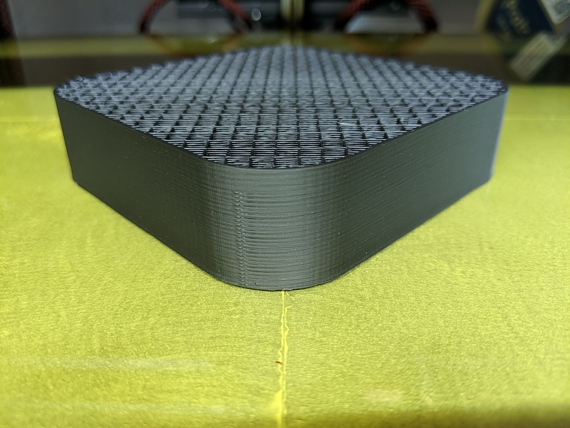
The artifacts at the start of the corners are due to my forgetting and leaving the "random" layer start point selected but you can also see some slight Z banding.Side View:
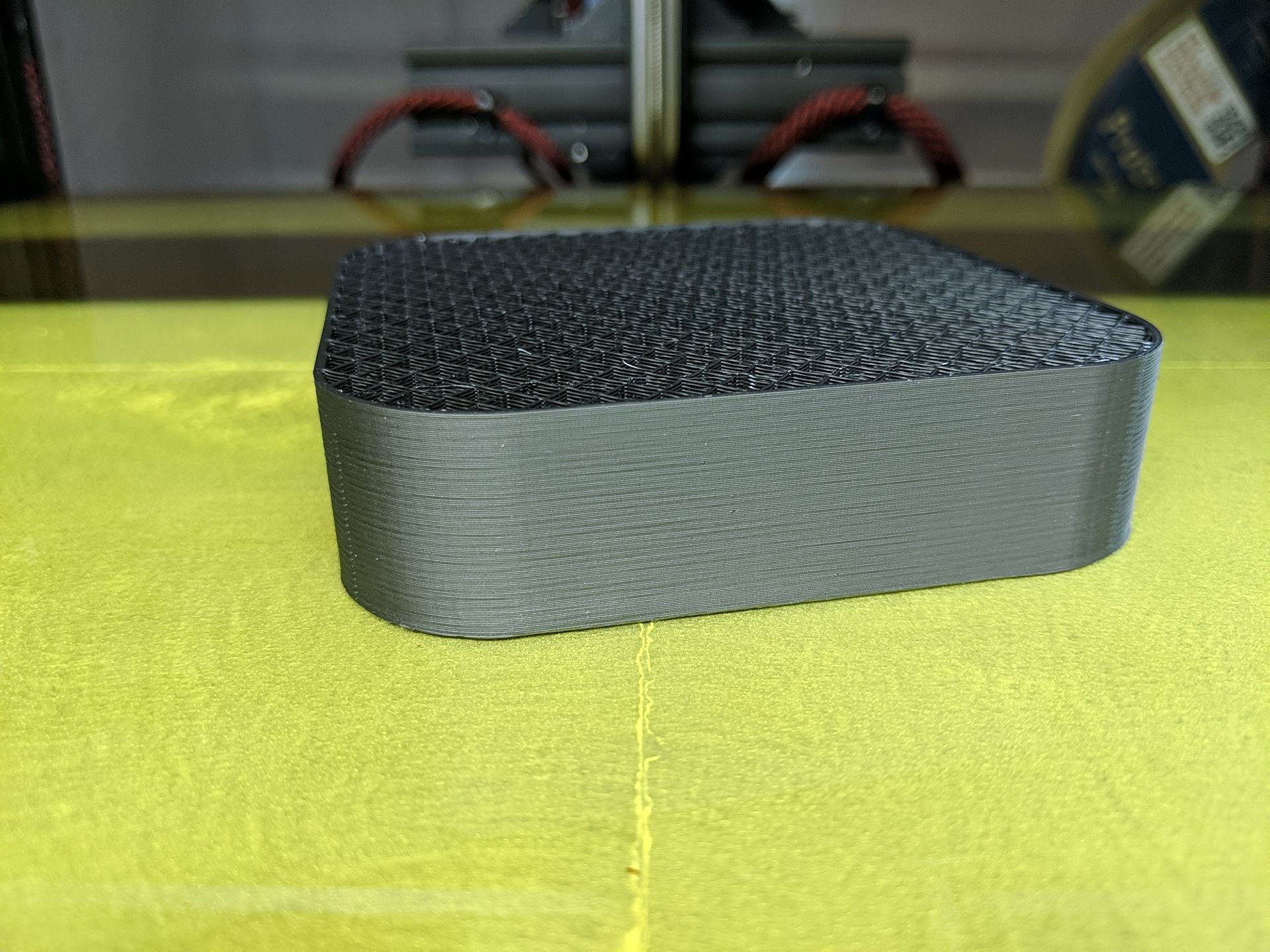
With a side view, you can see a little more banding but it's actually not bad. I had to look closely to see it with the naked eye.Back View:
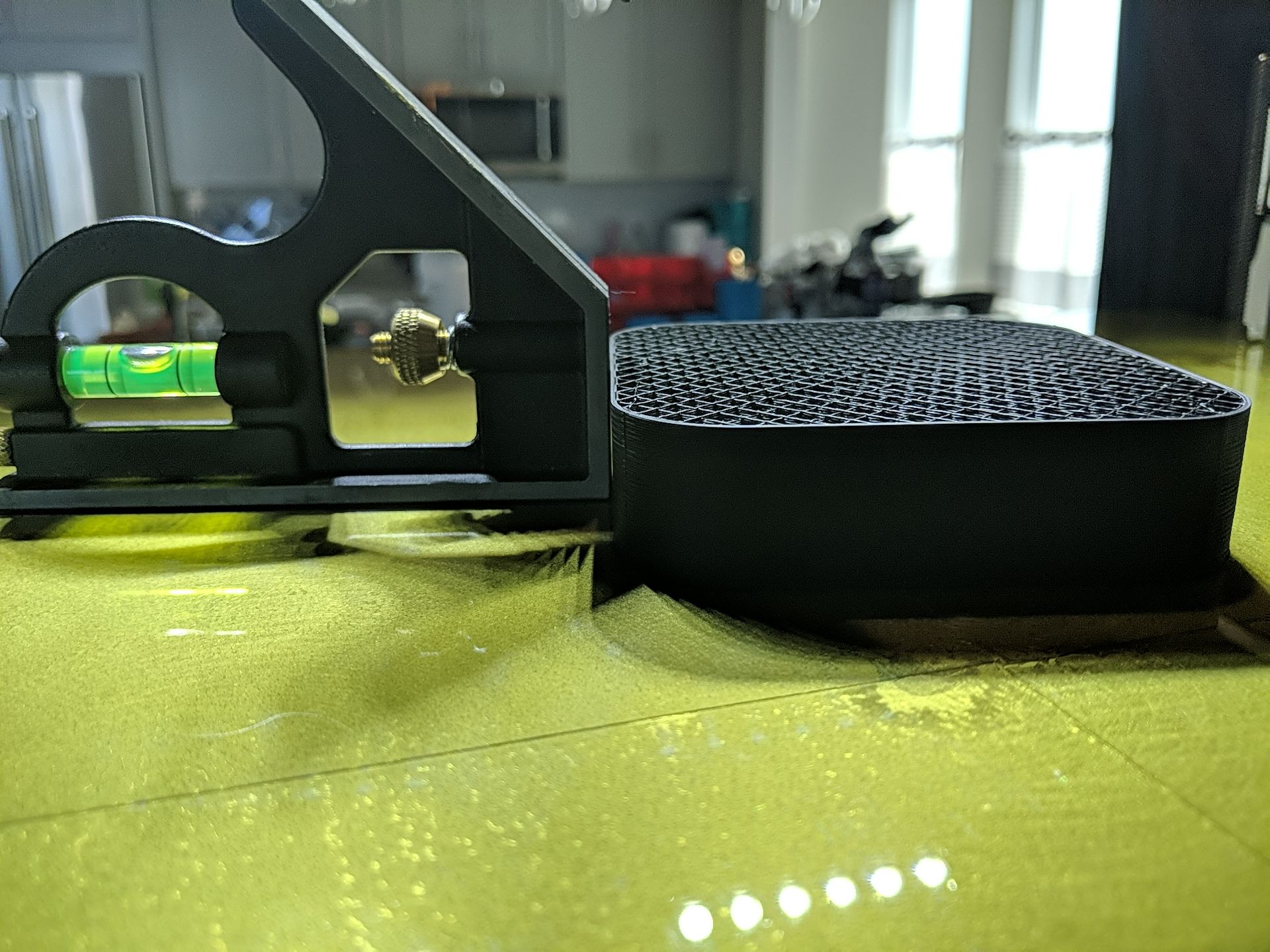
With the square butted up against the piece, you can see a slight gap that my feeler gauges say is about 0.06mm but it's on all 4 sides so it may be an artifact of the material shrinking and me not letting it cool evenly. There's a lot of surface are on the bottom and the PEI really grips it.Heightmap:
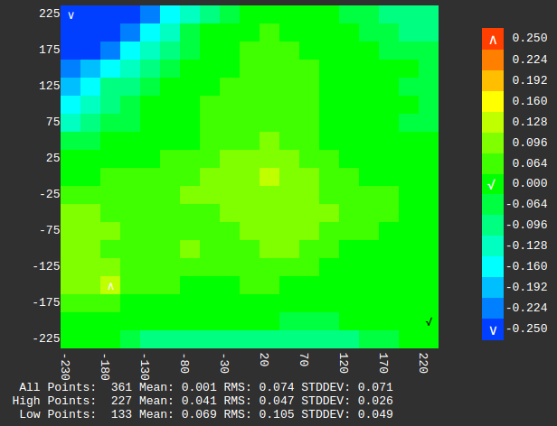
The heightmap looks pretty good. The dip in the back left corner is actually a deformation in the bed. The high point (0.106) is actually towards the front left (-180,-150) but it's a piece of something that got caught in the adhesive between the PEI and the bed surface.Next stop... A sharp cornered test cube and some real tuning.
-
Oh, I forgot to mention my heat treating setup...
Here's the center carriage plate vacuum pressed to a piece of borosilicate glass.

And surrounded by rice for better heat distribution.

Heated at 110C for 20 minutes then allowed to cool back to room temperature without opening the oven door..
Besides holding the piece flat, the vacuum seal also guards against moisture. Although the relative humidity is normally only in the teens here, I only have a gas oven and Methane + Oxygen = Carbon Dioxide + Water. Go figure.
-
Glad to see you're still working on your Black Beauty. I had been following you on the RR Forums when you still had the cross gantry setup.
As I'm currently trying to figure out where to go with my project and actually was leaning towards a cross gantry setup: what made you switch to CoreXY?!
-
Very nice!
-
@bberger said in Black Beauty Arises!:
Glad to see you're still working on your Black Beauty. I had been following you on the RR Forums when you still had the cross gantry setup.
Seems like an age ago.

As I'm currently trying to figure out where to go with my project and actually was leaning towards a cross gantry setup: what made you switch to CoreXY?!
The size of the printer places the nozzle right at my eye level, which I like, but with a true XY cartesian setup it also placed the front rail right in front of my face. It just got annoying. My design was also touchy to align and while it worked, a single tooth slip of a belt on a drive gear would result in a racked gantry. I'm not sorry I tried it by any means. I learned so much during the process.
The thing about CoreXY that I didn't like that started me down the cartesian XY route in the first place was the belts on multiple planes and the complexity of the routing. Also in my case, the 2 belts would each be over 2m long and I was worried about stretching. @mrehorstdmd's excellent forum and blog posts got me thinking again though and with the realization that, with the 600mm X span, I could use a belt twist at the back to keep the belts on the same plane without putting undue stress on them, I finally figured I'd give it a shot. I'm happy I did. I can now see the nozzle/print clearly and it's just not possible for the gantry to rack. It's also 2 less motors.
 The move to genuine Gates 9mm wide belts eliminated my concerns about stretching.
 -
I think that if you twisted the belts so that the smooth back sides were dragging on the separator you be less likely to wear the toothed sides of the belts and less likely to induce bumps in your prints from the teeth hitting the separator. At high speeds there is probably a zip-zip sound coming from the separator. That will go away if the smooth backs of the belts touch it instead of the teeth.
-
@mrehorstdmd The spacer is polished and the leading and trailing edges are tapered so I don't hear anything. I thought I tried with the smooth sides facing each other but for some reason I couldn't make the routing work. Maybe I was just being an idiot. I can't see it in my mind so I'll have to actually try it which I can do later today.
-
@mrehorstdmd O Wise Dentist... it don't work.
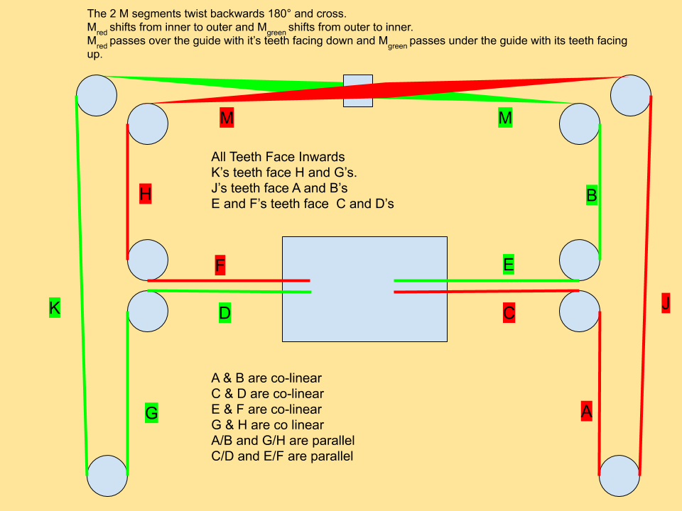
I cannot figure out any routing that will allow the 2 M segments to cross with their smooth surfaces facing each other unless I separate the segments vertically at the center guide. That however, makes the belts interface with the idlers at too great an angle for my taste.
Got any ideas???