ender 5 plus
-
@Phaedrux Sorry don't want to hijack this post , but I'm thinking I may finish up doing the same thing with the bltouch and the ender 5 +
What does bed level do ? probe the centre of the bed and set both corner to this level ?.
-
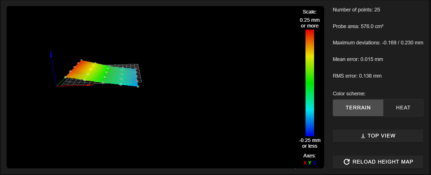
he only adjusts the lowest side and always down not flat.
when I raise right goes left after bottom,
when I raise left goes right after bottom
-
; Bed adjustment screw locations
M671 X-20:370 Y0:0 S2 ; leadscrew-locatiesI don't think your Y coordinate is correct. Your lead screws are in the middle of the bed along the Y axis, not at the front. According to your bed.g it should be Y165:165
I don't think that matters in this case, but it's something I noticed.
Your driver order looks correct to match your lead screw positions. Can you double check that the left motor is connected to driver 2 and the right to driver 4? The behaviour seems to indicate it's doing the reverse of what it should, and having the drivers reversed would do that.
The only other thing I can think of is maybe the IR probe not liking your build plate surface. Can you show a photo of the bed surface? Can you try putting a piece of plain white paper under where the probe samples?
-
@Kevin Hi , have you tried using ruler and not used someone else's setting for a different printer ?
on my ender 5 plus it is about 40mm from the nozzle to the centre of the leadscrew left and only 20mm right.https://duet3d.dozuki.com/Wiki/Bed_levelling_using_multiple_independent_Z_motors
Note: If you are experiencing the Z axis compensating in the opposite direction needed, that means your Z motors are swapped. You can either swap the X values in the M671 command, or swap the stepper motors plugged into the Duet.
your bed.g , shouldn't you home all axis first not after
; bed.g
; called to perform automatic bed compensation via G32
;
; generated by RepRapFirmware Configuration Tool v3.1.3 on Fri Jul 03 2020 20:35:09 GMT+0200 (Midden-Europese zomertijd)
M561 ; clear any bed transform
;G29  ; probe the bed and enable compensation

G30 P0 X5 Y165 Z-99999  ; probe near a leadscrew left
G30 P1 X325 Y165 Z-99999 S2; probe near a leadscrew right

G28 XY: HOME
G32
Leadscrew adjustments made: 0.051 -0.017, points used 2, (mean, deviation) before (0.016, 0.021) after (-0.000, 0.000)WORKED FOR ME
-
@Phaedrux
https://duet3d.dozuki.com/Wiki/Bed_levelling_using_multiple_independent_Z_motorsRecommendations
If you have just 2 Z motors, one at each end of the X axis, then set the Y coordinates of the leadscrews in the M671 command to be equal (the value doesn't matter, so you can use zero). Use at least two probe points, one at each end of the X axis. All your probe points should have the same Y coordinate, which should be at or near the middle of the printable range.
Note: If you are experiencing the Z axis compensating in the opposite direction needed, that means your Z motors are swapped. You can either swap the X values in the M671 command, or swap the stepper motors plugged into the Duet. -
it works for me , but had to run G32 twice .
The first go was near ,not sure if was due to my .5mm limit .


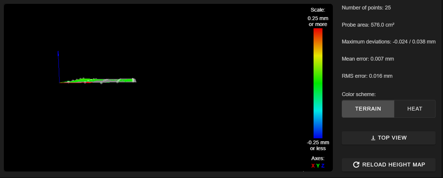
19/08/2020, 18:29:16 G29
25 points probed, min error -0.024, max error 0.038, mean 0.007, deviation 0.016
Height map saved to file 0:/sys/heightmap.csv
19/08/2020, 18:27:02 G32
Leadscrew adjustments made: 0.079 -0.038, points used 2, (mean, deviation) before (0.021, 0.036) after (-0.000, 0.000)
19/08/2020, 18:25:43 G29
25 points probed, min error -0.043, max error 0.061, mean 0.002, deviation 0.030
Height map saved to file 0:/sys/heightmap.csv
19/08/2020, 18:23:33 G32
Leadscrew adjustments made: 0.341 -0.295, points used 2, (mean, deviation) before (0.023, 0.194) after (-0.000, 0.000) -
@peter247
I had measured but I don't have an original hotend.
i have switched the connection on the stepper motors and it works.
not perfect yet because I have different values every timehow do you use it? first mesh G29 then G32 or first G32 then G29

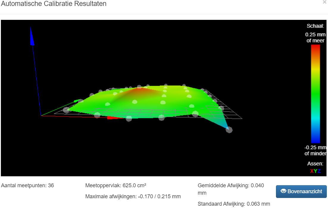
 these are 3 repetitions in a row and then done mesh
 -
Normally you'd use G28 > G32 > G29 but it really depends on how you have things configured. Usually G28 would home the Axis. G32 would execute whatever you have in bed.g which might be tilt correction, and then you'd use G29 after the tilt correction to map out the surface details.
-
thanks for response
i am using combined macros with G28> G32> G29
-
@Kevin I did a z home , g32 then a g29 , then a z home.
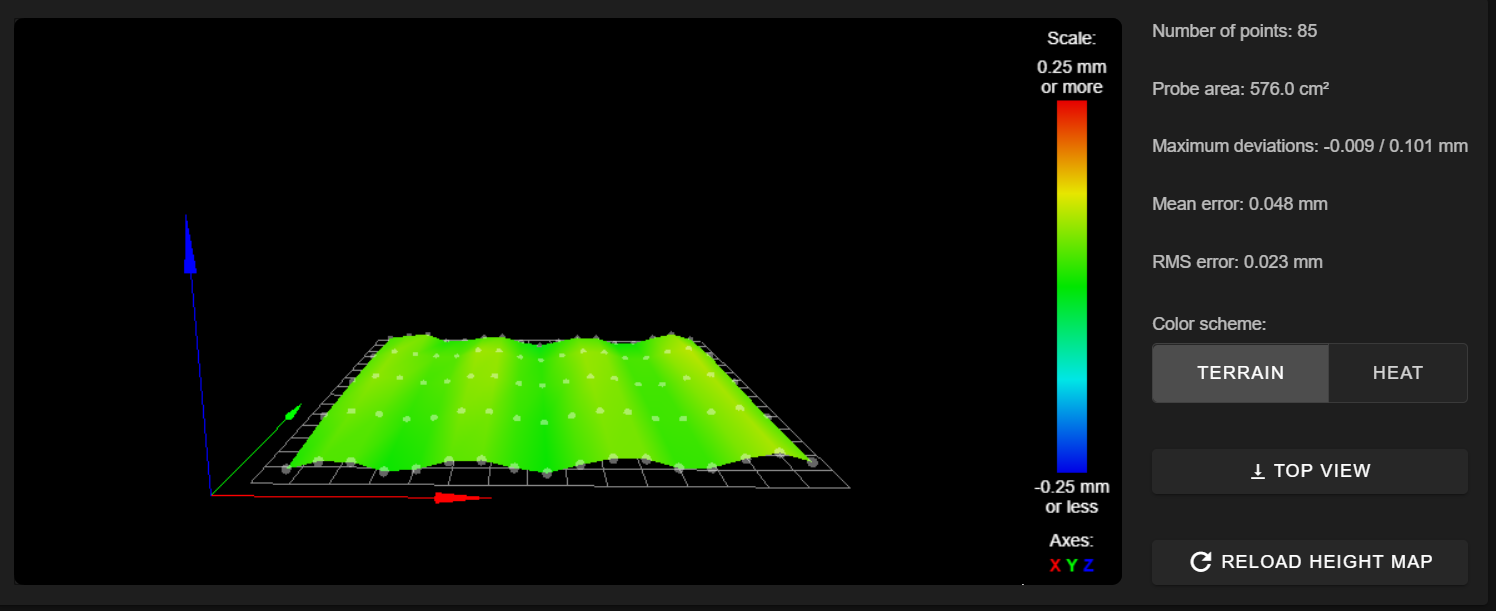
Mine a have a nice little ripple , but not red spots .
